

 English
 Français
 Español
 Português
 عربى







Application ScopeThe GPX129-09T fiber optic distribution frame is used to connect, distribute, and manage fiber optic cables and optical communication equipment. It is suitable for large-capacity fibe...
See DetailsHigh-Density 19-Inch Optical Distribution Frame for Reliable Fiber Management
Content
- 1 1. The Role of an Optical Distribution Frame in Modern Networks
- 2 2. Product Overview and Core Design
- 3 3. Main Product Features
- 4 4. Technical Parameters
- 5 5. How the Fiber Management System Works
- 6 6. Advantages Over Less Integrated Competitors
- 7 7. Manufacturing Process and Quality Strengths
- 8 8. Installation Recommendations
- 9 9. Operating Environment and Reliability
- 10 10. Application Areas
- 11 11. Maintenance and Network Management Benefits
- 12 12. Selecting the Right Configuration
- 13 13. Why Manufacturing Experience Matters to Buyers
- 14 14. Project Planning and Total Cost Considerations
- 15 15. Recommended Quality and Commissioning Procedure
- 16 16. Frequently Asked Questions
- 16.1 What is the capacity of the WM-ODF-56SC?
- 16.2 What type of adapter does the product support?
- 16.3 Can the unit be installed in a standard communication cabinet?
- 16.4 What are the product dimensions?
- 16.5 Can the frame accommodate different cable constructions?
- 16.6 Why does the unit use a drawer structure?
- 16.7 What optical wavelengths are covered by the stated specifications?
- 16.8 What insertion loss is specified?
- 16.9 What return-loss values are listed?
- 16.10 What accessories are included in the listed configuration?
- 16.11 Is the product suitable for railway and transit applications?
- 16.12 How should unused ports be maintained?
- 16.13 Can customized configurations be requested?
- 17 17. Conclusion
- 18 References
- 19 Product: WM-ODF-56SC 19inch ODF
Modern communication networks depend on physical fiber infrastructure that is orderly, accessible, and capable of supporting continuous service growth. As fiber counts increase in telecommunications rooms, data centers, railway communication facilities, enterprise networks, and access-network cabinets, the optical distribution frame becomes more than a passive metal enclosure. It becomes the central point where incoming optical cables are secured, fibers are spliced, pigtails are protected, and connections are distributed for equipment or end users.
The WM-ODF-56SC 19-inch ODF is designed for these demanding applications. It combines fiber splicing, optical distribution, cable management, and protection within a compact 3U rack-mount structure. With a capacity of 56 fibers and compatibility with SC adapters, the unit provides a practical solution for network operators that need high density without sacrificing maintainability. Its drawer-style construction, rear cable-entry arrangement, splice-tray organization, and integrated cable protection features support efficient installation and long-term operation.
This article examines the design, operating advantages, technical characteristics, manufacturing strengths, installation practices, and application value of this high-density optical distribution frame. It also explains how the product compares with less integrated alternatives and why controlled manufacturing processes are important when passive optical equipment is deployed in critical networks.
1. The Role of an Optical Distribution Frame in Modern Networks
An optical distribution frame, commonly called an ODF, is used to organize and protect optical fibers at a network termination or cross-connection point. Optical cables entering a facility usually contain multiple fibers that must be separated, routed, spliced, terminated, labeled, and connected to equipment or distribution cables. Without a dedicated management structure, these operations can result in excessive bending, tangled patch cords, poor identification, and difficult maintenance.
The ODF provides a defined physical environment for these activities. Incoming cables are fixed at the rear of the frame, the cable sheath is opened and managed, individual fibers are guided into a splice tray, and the fibers are connected to pigtails. The pigtails then terminate in adapter positions on the front panel. Patch cords can be connected from the front side to optical transmission equipment, splitters, active network devices, or other distribution points.
This arrangement separates the permanent cable installation from the flexible patching function. When a network is upgraded, the operator can change a front-side patch connection without disturbing the spliced portion of the incoming cable. When troubleshooting is required, the technician can trace a fiber through an organized route rather than searching through an unstructured bundle.
The value of an ODF is therefore determined by more than its nominal fiber capacity. Important factors include rack compatibility, cable retention, bend-radius control, splice protection, access to the working area, adapter quality, mechanical strength, installation efficiency, and the ability to maintain the system over many years.
2. Product Overview and Core Design
The WM-ODF-56SC is a standard 19-inch rack-mount optical distribution frame with a 3U height and a nominal capacity of 56 SC connections. Its stated mechanical dimensions are approximately 132.5 millimeters in height, 482.6 millimeters in width, and 407 millimeters in depth. The 482.6-millimeter width corresponds to the widely used 19-inch rack standard, allowing the unit to be installed in compatible cabinets, distribution frames, equipment rooms, and communication enclosures.
The product integrates the main functions required in a compact fiber management unit. These functions include optical cable fixation, fiber separation, fiber protection, fiber splicing, pigtail routing, adapter termination, and front-side distribution. By combining these functions in one structured enclosure, the unit reduces the need for separate mounting accessories and helps create a consistent installation format.
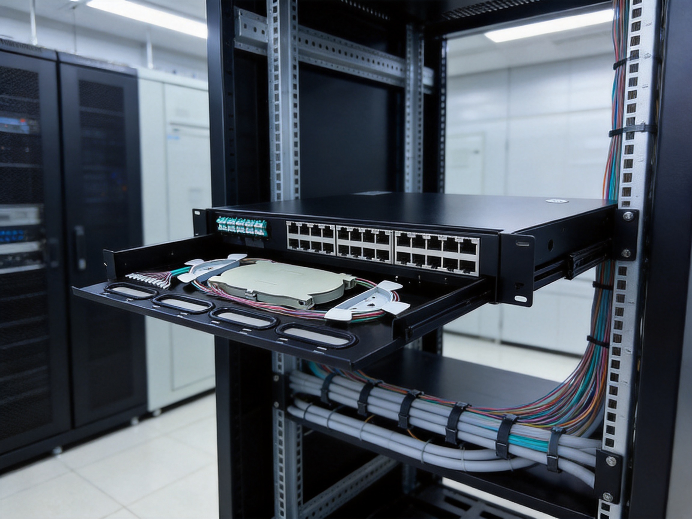
The frame uses a drawer-style arrangement. During splicing or inspection, the working section can be pulled outward to provide better access. After the operation is completed, it can be returned to its normal position inside the rack. A limiting mechanism helps prevent excessive extraction, reducing the possibility of pulling, twisting, or damaging the fibers connected to the tray.
The rear section contains the cable-entry and cable-splitting area. Incoming optical cable is introduced from the back, fixed in place, opened and stripped as required, and then routed through the internal guide system. The separated fibers are placed into the splice tray, where they are joined to pigtails. This design keeps the incoming cable mechanically stable while providing a controlled path to the front adapter panel.
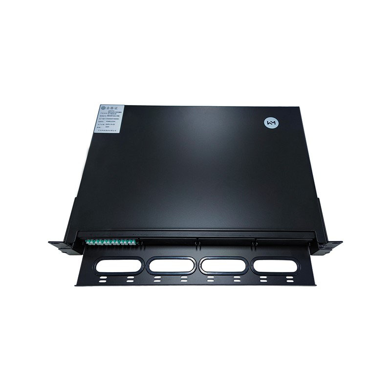
WM-ODF-56SC 19inch ODF
3. Main Product Features
3.1 Standard 19-Inch Rack Compatibility
The standard 19-inch construction is one of the product’s most important practical advantages. Network operators commonly use cabinets and racks built around this dimension, so a compliant frame can be installed without redesigning the entire equipment layout. The unit can be mounted in a central office rack, an enterprise communication cabinet, a railway signaling communication cabinet, a data room enclosure, or a field distribution cabinet designed for standard rack equipment.
Standardization also simplifies replacement and expansion. A network planner can allocate a known 3U space for the ODF and reserve adjacent rack positions for optical transmission equipment, Ethernet switches, power systems, or monitoring devices. If several distribution frames are required, they can be installed in a predictable vertical arrangement.
3.2 High Fiber Density in a Compact Format
A capacity of 56 cores in a 3U enclosure provides a useful balance between density and working space. Extremely compact products may save rack units but leave insufficient room for fiber routing, identification, and service operations. Larger frames may offer more room but consume valuable cabinet space. The 56-core format is suitable for many access, enterprise, transport, and local distribution applications where moderate-to-high capacity is required.
The product supports SC adapters and is suitable for ribbon, bundled, and single-core cable arrangements. This flexibility allows the same basic frame design to be considered for different cable architectures. It also helps contractors and network operators reduce the number of enclosure types that must be stocked for routine deployments.
3.3 Integrated Splicing and Distribution
Some low-cost fiber panels provide adapter positions but offer limited space or structure for cable splicing. In such installations, separate splice boxes, loosely positioned trays, or improvised cable-management methods may be needed. The WM-ODF-56SC integrates the splicing and distribution functions in one unit. Incoming fibers can be spliced to pigtails within the protected internal area, while the resulting connections are presented at the front adapter panel.
This integrated approach improves the relationship between the splice area and the termination area. It reduces the distance that pigtails need to travel, supports more orderly routing, and makes it easier for technicians to follow a fiber from cable entry to adapter position. It also minimizes the number of independent housings that must be installed and maintained.
3.4 Cable Fixing and Fiber Protection
Mechanical movement is a major risk to optical fibers. If the incoming cable is not properly secured, its weight, vibration, or accidental pulling can transfer force to splice points. The rear cable fixation arrangement helps hold the cable in position and reduces stress on the internal fibers.
Inside the unit, fiber guides and the splice tray help control the fiber path. A spiral protection tube can be used to organize and shield routed fiber sections. Heat-shrink protection tubes can protect individual splice points after fusion splicing. These accessories contribute to a more durable installation and help reduce the likelihood of microbending, accidental abrasion, or fiber displacement during maintenance.
3.5 Drawer-Type Service Access
Splicing inside a fixed, deep cabinet can be uncomfortable and inefficient. The drawer structure allows the working section to be pulled forward, giving the technician improved visibility and access to the splice tray. This is especially valuable when the ODF is installed in a crowded rack with limited rear or side access.
The extraction limit is an important detail. A drawer that pulls out without restraint may place excessive tension on fiber loops or pigtails. The limiting device helps keep the movement within a controlled range. This is a simple mechanical feature, but it contributes directly to service safety and reduces the chance of damage caused by overextension.
3.6 Durable Material Selection
The adapter panel and main ODF structure are made from metal material with a sprayed surface finish. A metal enclosure provides rigidity, protects internal components, and helps the frame withstand normal handling during installation and maintenance. The surface treatment improves appearance and contributes to resistance against routine wear and environmental exposure.
The splice tray and cable-guiding components use polypropylene, commonly known as PP. This material is lightweight, flexible, and resistant to many common environmental influences. Its flexibility is useful for fiber routing because cable guides and trays need to support the fiber without creating sharp edges or unnecessary stress. The combination of a rigid metal frame and lightweight polymer management parts provides a practical balance of strength and handling convenience.
4. Technical Parameters
Item | Specification | Application Significance |
Product model | WM-ODF-56SC | Identifies the 56-core SC optical distribution frame |
Rack format | 19-inch standard | Compatible with common communication racks and cabinets |
Height | 3U | Supports efficient use of rack space |
Dimensions | 132.5 mm × 482.6 mm × 407 mm | Provides a defined installation envelope |
Fiber capacity | 56 cores | Suitable for medium- and high-density distribution points |
Adapter type | SC available | Supports widely used SC optical connections |
Working wavelengths | 850 nm, 1310 nm, and 1550 nm | Suitable for common multimode and single-mode testing ranges |
Insertion loss | Not more than 0.3 dB | Helps control connection-related optical attenuation |
Return loss | PC ≥ 40 dB; UPC ≥ 50 dB; APC ≥ 60 dB | Supports low-reflection optical links according to connector type |
Electrical strength | At least 3 kV DC for 1 minute | Provides a stated dielectric withstand level |
Insulation resistance | At least 1,000 MΩ at 500 V DC | Supports electrical isolation of the enclosure system |
Insertion life | 500 cycles | Indicates repeated connection and disconnection capability |
The optical parameters are important because an ODF is part of the signal path. An insertion loss of no more than 0.3 dB helps preserve the available optical power budget when the frame is correctly installed and used with compatible adapters and connectors. Return-loss values vary according to the connector polishing method. PC, UPC, and APC configurations provide different reflection characteristics, with APC generally offering the highest stated return-loss performance among the listed options.
The specified working wavelengths of 850 nm, 1310 nm, and 1550 nm cover common optical communication testing and transmission windows. The 850-nanometer range is frequently associated with multimode systems, while 1310 and 1550 nanometers are widely used in single-mode communication networks. Actual system suitability remains dependent on the installed fiber, connector type, transceiver, and network design.
5. How the Fiber Management System Works
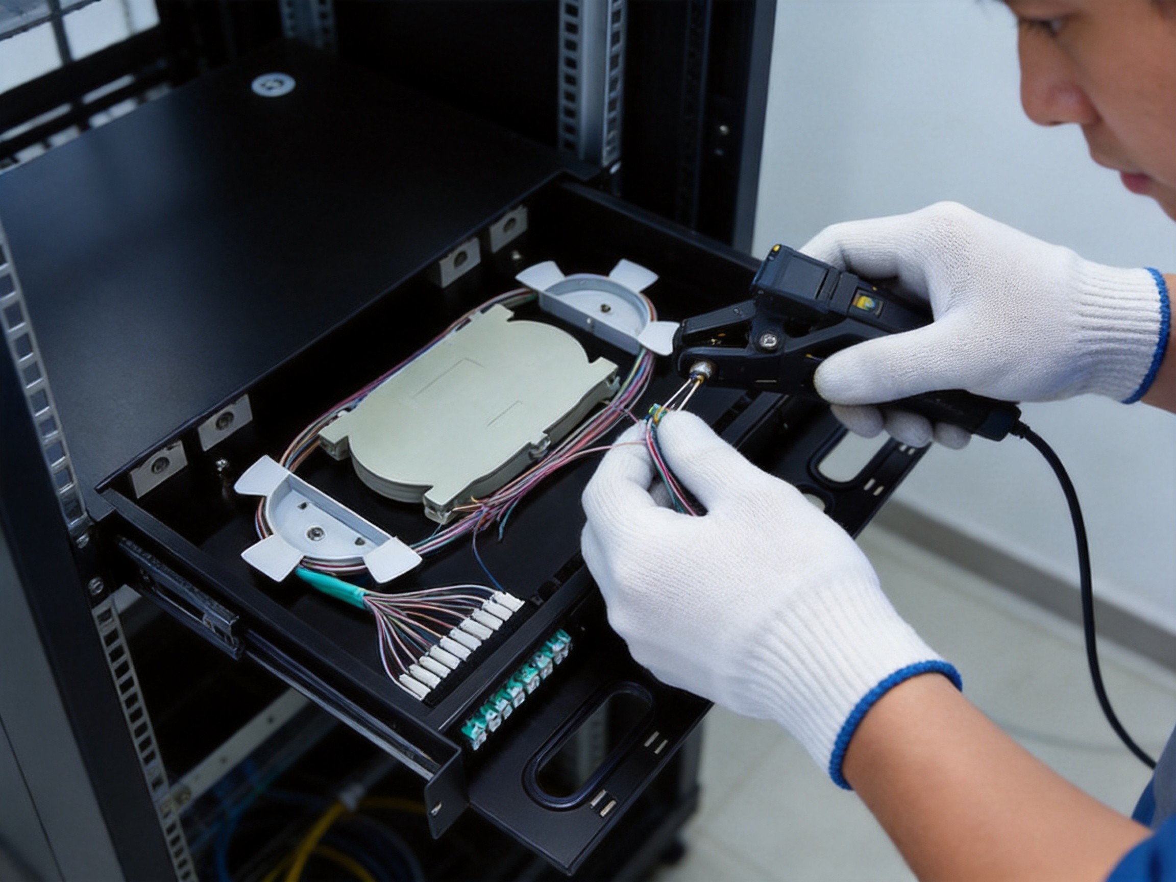
The fiber cable enters through the rear of the ODF. The cable is first secured by the cable clamp or fixing plate so that mechanical loads are not transferred to the splicing area. The outer jacket is then opened according to the cable construction. Strength members, tubes, ribbons, or individual fibers are prepared using procedures appropriate to the cable type.
After preparation, the fibers pass through the internal cable guide or fiber spool. The guide helps maintain a controlled bend path and prevents the fibers from being placed directly against sharp or unprotected surfaces. The fibers are then routed into the splice tray. Each fiber is spliced to a pigtail, and the splice is protected with a heat-shrink tube or another approved splice-protection method.
The pigtails are organized inside the tray and routed toward the adapter panel. Each pigtail is connected to its corresponding SC adapter. From the front of the ODF, patch cords can then be connected to active equipment, another distribution point, a test instrument, or an end-user network termination.
This sequence creates a clear division between cable entry, fiber splicing, and front-side patching. It also allows future work to be performed with less risk to the permanent cable. The technician can remove or replace a patch cord while leaving the splice tray undisturbed.
The accessory list includes several pigtail and patch-cord configurations, including SC/UPC-to-LC/UPC and SC/UPC-to-FC/UPC options. It also includes 0.9-millimeter SC/UPC pigtails, spiral protection tubing, 45-millimeter heat-shrink tubes, cable clamps, snap nuts and screws, and cable ties. These accessories support initial assembly and help create a complete working installation rather than a bare enclosure that requires extensive additional sourcing.
6. Advantages Over Less Integrated Competitors
6.1 Better Use of Rack Space
A key competitive advantage is the combination of 56-core capacity and a 3U rack footprint. Products with lower capacity may require more rack units or multiple panels for the same number of fibers. Larger, loosely organized frames may consume more cabinet space than necessary. The 3U format helps network planners balance density with serviceability.
Space efficiency is particularly valuable in railway communication rooms, data centers, and urban infrastructure cabinets where rack space is limited. Reducing the number of required enclosures can also reduce cable congestion, installation labor, and the number of potential points of failure.
6.2 Easier Maintenance Than Fixed Panels
Fixed panels can be difficult to service when splice trays are positioned deep inside a cabinet. The drawer design of this product brings the working area forward and supports more comfortable access. This can reduce the time required for fiber identification, testing, re-splicing, and inspection.
Improved access also reduces the chance that a technician will bend, pull, or disconnect an unrelated fiber while working on a specific connection. In a dense network, this operational benefit can be more significant than a small difference in initial purchase price.
6.3 More Complete Fiber Protection
Some competing solutions emphasize connector density but provide limited mechanical support for the incoming cable or spliced fibers. The WM-ODF-56SC addresses several stages of protection, including cable clamping, fiber guiding, splice-tray storage, spiral tubing, heat-shrink protection, and controlled drawer movement.
These features work together. Cable fixation prevents external tension, the guide path controls fiber movement, the tray separates and stores the fibers, and splice sleeves protect the fusion points. A single feature cannot replace the complete management system, so the integrated design offers a stronger practical solution than a simple adapter plate.
6.4 Flexible Cable Compatibility
Compatibility with ribbon, bundled, and single-core cables expands the product’s application range. Network contractors may encounter different cable constructions across access, transport, enterprise, railway, and industrial projects. A frame that can accommodate multiple cable types reduces the need to select an entirely different enclosure for every project.
Flexibility is also helpful during network modernization. An existing site may contain older bundled cable while a new extension uses ribbon or single-core cable. A versatile ODF can support the transition without requiring separate cabinet architectures.
6.5 Practical Accessory Configuration
The listed accessory package includes essential installation and protection components. The presence of pigtails in several quantities and patch cords with different connector combinations can simplify project preparation. Operators can select the appropriate cord length and connector arrangement based on equipment position and routing requirements.
Accessory availability also helps improve consistency. When compatible components are sourced together, the installer is less likely to use unsuitable tubing, poorly matched pigtails, or improvised cable-retention methods. Consistent accessories can lead to more predictable optical performance and easier future maintenance.
6.6 Optical Performance for Common Network Environments
The stated insertion-loss and return-loss values support common optical communication requirements when the frame is correctly terminated, cleaned, and tested. Low insertion loss helps preserve system margin, while good return loss reduces reflected optical energy that can interfere with sensitive transmitters or receivers.
For network operators, the advantage is not simply a specification on paper. Reliable optical performance reduces the risk of unexplained link attenuation, intermittent service, and repeated troubleshooting. It also supports the testing procedures used during commissioning and maintenance.
7. Manufacturing Process and Quality Strengths
The quality of a rack-mounted ODF depends heavily on manufacturing discipline. The unit must combine metal fabrication, surface finishing, polymer component production, adapter integration, accessory preparation, and final inspection. Variations in any of these processes can affect installation accuracy, fiber safety, or long-term serviceability.
7.1 Engineering and Product Design
Manufacturing begins with a product design that defines the rack envelope, internal fiber path, adapter arrangement, splice-tray dimensions, drawer travel, cable-entry position, and fixing points. The design must allow the frame to fit standard cabinets while leaving sufficient clearance for connectors and patch cords.
Mechanical tolerances are important in this stage. Mounting holes must align with rack rails, the drawer must move smoothly, and the splice tray must remain secure in both the extended and retracted positions. The design also needs to prevent sharp edges or tight turns that could damage fiber coatings.
Wanma Technology Co., Ltd. has long-term experience in communication cabinets, communication electronic equipment, and passive optical components. This background supports product development based on practical network requirements rather than focusing only on appearance or nominal capacity. Experience across cabinets and passive optical products is valuable because an ODF must function as part of a complete physical infrastructure system.
7.2 Metal Fabrication
The main frame and adapter panel require accurate metal processing. Cutting, punching, bending, drilling, and forming operations must be controlled so that the finished enclosure remains square and stable. Accurate fabrication helps ensure that the frame can be installed without forcing the mounting points or distorting the chassis.
After forming, edges should be treated to reduce sharp surfaces. This is important for both worker safety and fiber protection. A poorly finished edge can damage cable jackets or fiber tubes during installation. Controlled production procedures help ensure that the enclosure is robust while maintaining smooth cable-contact areas.
7.3 Surface Treatment
The sprayed metal surface provides an attractive and durable finish. Surface preparation is essential because contamination, poor adhesion, or uneven coating can reduce durability. A controlled process generally includes cleaning, preparation, coating application, and curing. Consistent coating thickness helps maintain a uniform appearance and protects the metal from ordinary handling and environmental exposure.
For communication rooms and equipment cabinets, a clean and consistent finish has practical value. It makes the equipment easier to identify, gives the installation a professional appearance, and helps the enclosure remain presentable during years of service visits.
7.4 Polymer Component Production
The splice tray and cable guides are made from PP material. Polymer parts must be designed and produced with suitable wall thickness, flexibility, and dimensional stability. If a tray is too rigid, it may be difficult to handle. If it is too flexible, it may not retain the fibers securely. Balanced material selection and mold control help produce components that are light but dependable.
Polypropylene is also useful because it can be formed into complex cable-management shapes. Trays can include fiber-retention features, routing channels, and splice-sleeve locations. These details help technicians arrange fibers consistently and reduce movement inside the tray.
7.5 Assembly and Integration
Assembly brings together the metal enclosure, adapter panel, drawer mechanism, splice tray, cable guides, fixing hardware, and accessories. The assembly process must ensure that moving parts operate correctly and that the fiber-management path is not obstructed by screws, brackets, or misaligned panels.
Adapters must be seated correctly in the panel, and pigtails must be routed without excessive tension. The drawer-limiting system must be checked to ensure that it restricts travel while still allowing adequate access. Cable clamps and mounting hardware must be supplied in a way that supports consistent field installation.
7.6 Optical and Mechanical Inspection
Inspection may include dimensional checks, visual examination, adapter alignment, movement testing, and optical performance verification. Insertion loss and return loss should be evaluated using appropriate test equipment and compatible reference procedures. The electrical strength and insulation-resistance values stated for the product also require suitable testing methods when applicable to the complete assembly.
Repeated insertion testing is another important quality activity. The stated insertion life of 500 cycles indicates that the connection interface is intended to tolerate repeated mating and unmating. This is useful for maintenance, network reconfiguration, and test operations where connectors may be accessed many times over the service life.
Wanma Technology’s experience in manufacturing and supplying communication infrastructure products supports a quality approach that includes production control, product inspection, packaging management, and delivery coordination. The company serves customers in more than 20 countries and regions, including markets in North America, Europe, Africa, and Oceania. International project experience can strengthen attention to documentation, packaging protection, configuration accuracy, and customer-specific requirements.
8. Installation Recommendations
8.1 Rack Preparation
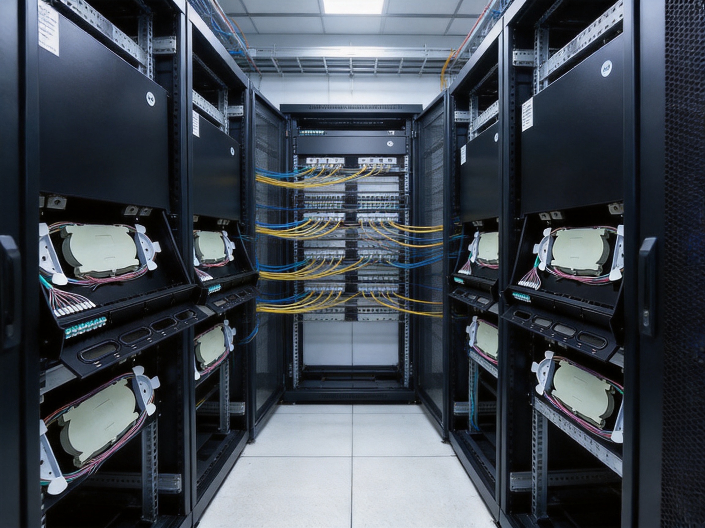
Before installation, confirm that the cabinet provides a standard 19-inch mounting position and at least 3U of usable vertical space. Check the rack depth because the product depth is approximately 407 millimeters, while additional clearance may be needed for rear cable routing and front patch-cord bend radius.
The rack should be securely anchored and positioned in an environment that meets the specified operating conditions. The working temperature range is approximately minus 25 to plus 40 degrees Celsius. The broader environmental temperature range is listed as approximately minus 40 to plus 60 degrees Celsius, while the storage temperature range is approximately minus 25 to plus 55 degrees Celsius.
8.2 Cable Entry and Fixation
Incoming cables should be routed from the rear with sufficient service length. The cable clamp should hold the cable jacket or approved strength member without crushing the cable. The installer should avoid placing the cable under tension and should maintain the manufacturer’s recommended bend radius for the specific cable construction.
After securing the cable, remove the outer jacket carefully. Do not allow tools to contact the fibers or tubes. Strength members should be cut and fixed according to the cable design. All unused openings should be managed appropriately to prevent loose parts or excessive contamination from entering the enclosure.
8.3 Splicing and Tray Organization
Fibers should be cleaned, identified, and routed into the splice tray in a consistent sequence. Each fiber should have enough slack for future re-splicing but should not be stored in a way that creates sharp bends or crossing loops. Splice sleeves should be placed in their designated positions, and the tray cover should be installed after the work is inspected.
Use spiral protection tubing where required to organize grouped fibers. Cable ties should be applied carefully and should never be tightened to the point that they deform fiber tubes or impose pressure on coated fibers. Clear labeling is recommended at the cable-entry point, splice tray, adapter panel, and connected equipment.
8.4 Front-Side Connection
SC adapters and connectors should be inspected and cleaned before mating. Dust caps should remain in place on unused ports. Patch cords should be routed with gradual bends and should not be allowed to hang from the adapter. Excessive weight or side loading can reduce connection reliability.
Where the accessory set includes SC/UPC-to-LC/UPC or SC/UPC-to-FC/UPC cords, confirm that the connector polishing type and equipment interface are compatible. Connector types should not be mixed without suitable adapters or verified compatibility.
9. Operating Environment and Reliability
The product is specified for operation in a relative humidity of no more than 85 percent at 30 degrees Celsius. The stated air-pressure range is approximately 70 to 106 kilopascals. These values cover many indoor communication-room and equipment-cabinet conditions, but the installation environment should still be evaluated for condensation, dust, vibration, chemical exposure, and water ingress.
Although an ODF is passive, environmental conditions can affect its performance. Moisture can contaminate connector end faces and metal surfaces. Dust can increase insertion loss. Excessive vibration can loosen hardware or disturb cable routing. High temperatures can affect cable materials and polymer components. Proper cabinet selection, room ventilation, and routine inspection help maintain stable operation.
In railway and urban transit applications, mechanical conditions may be more demanding than in a quiet office equipment room. The frame should be mounted securely, cables should have appropriate strain relief, and all fasteners should be checked during scheduled maintenance. The rigid metal construction and cable-fixing features are especially valuable in installations where vibration or repeated service access is expected.
10. Application Areas
10.1 Telecommunications Networks
Telecommunications operators can use the frame at fiber distribution points, local exchange facilities, access-network rooms, and aggregation locations. Its 56-core capacity is suitable for organizing subscriber-facing fibers, feeder cables, or equipment interconnections in a structured rack environment.
10.2 Enterprise and Campus Networks
Enterprise communication rooms often need a clear separation between incoming outside-plant cables and internal patching. The ODF can provide a stable termination point for campus backbone fibers, building-to-building links, and connections to data-center or server-room equipment.
10.3 Railway and Urban Rail Transit
Railway and urban rail systems use optical networks for communications, signaling support, surveillance, passenger information, control systems, and operational data. In these environments, organized fiber management is important because maintenance windows may be limited and service continuity is critical. A rack-mounted frame with cable fixation, splice protection, and controlled access can help technicians maintain clear records and reduce accidental disruption.
10.4 Data Centers and Central Equipment Rooms
Data centers require high-density connections, careful labeling, and efficient use of rack space. The 3U format allows the ODF to be positioned near optical switches, transmission equipment, and patching systems. Front-side access supports faster changes, while the protected rear splice area keeps permanent cable terminations separated from frequent patch-cord activity.
10.5 5G and FTTH Infrastructure
Fiber is a fundamental part of 5G transport and access-network modernization. Fiber-to-the-home deployments also depend on organized feeder and distribution connections. The ODF can be used where incoming fiber cables must be spliced to pigtails and presented for distribution toward optical line terminals, aggregation equipment, splitters, or downstream access points.
As networks evolve, the physical layer must accommodate new wavelengths, higher bandwidth, and additional connections. A modular rack-mounted frame can support staged expansion and organized migration without requiring a complete replacement of the existing cabinet structure.
11. Maintenance and Network Management Benefits
Good fiber management reduces the time required to identify and restore a failed connection. Every cable, splice, pigtail, and adapter should be labeled according to the network documentation. The drawer and splice tray should be returned to their normal positions after work so that the enclosure remains protected and the rack remains orderly.
Routine maintenance should include connector cleaning, inspection of patch-cord routing, examination of cable clamps, verification of tray covers, and checking for excessive fiber slack or sharp bends. Unused adapters should remain capped. If a connector shows contamination or physical damage, it should be cleaned or replaced according to the applicable maintenance procedure.
The product’s organized layout also supports future audits. Technicians can compare physical port assignments with network records, verify fiber continuity, and identify unused capacity. This can be particularly helpful in large projects where multiple ODFs are installed across equipment rooms, stations, buildings, or regional network facilities.
Because the ODF separates permanent splices from front-side connections, ordinary patching work can often be completed without opening the splice area. This reduces exposure of the fibers and supports a lower-risk maintenance workflow.
12. Selecting the Right Configuration
Before purchasing or deploying the frame, the network designer should confirm the required adapter type, connector polishing method, pigtail length, cable construction, and patch-cord interface. SC/UPC, SC/APC, LC, and FC configurations have different mechanical and optical characteristics. The selected configuration must match the connected equipment and the link budget.
The quantity of pigtails should correspond to the number of fibers being terminated. In a full 56-core deployment, the accessory list includes 56 0.9-millimeter SC/UPC pigtails. A partial deployment may use fewer pigtails while reserving the remaining adapter positions for future growth.
Patch-cord length should be selected according to the distance between the ODF and connected equipment. The accessory list includes lengths of 5, 10, 15, and 20 meters in selected connector combinations. Proper length selection avoids excessive slack, reduces congestion, and supports better bend-radius control.
Project specifications may also require custom labeling, alternative adapter arrangements, different pigtail polishing, or modified accessory quantities. Wanma Technology’s focus on self-developed products and integrated customized solutions can be valuable when standard catalog configurations need to be adapted to a specific installation.
13. Why Manufacturing Experience Matters to Buyers
Buyers of passive optical equipment are not purchasing only a box and a set of adapters. They are purchasing a physical platform that must remain stable through installation, commissioning, expansion, testing, and long-term maintenance. Manufacturing experience affects the consistency of dimensions, finish, fiber routing, adapter alignment, and accessory compatibility.
A supplier with experience in communication cabinets understands how rack equipment is installed, how cable loads affect enclosures, and how technicians work inside crowded cabinets. Experience with passive optical components adds understanding of connector performance, splice protection, and optical testing. Experience serving international customers contributes to project coordination, packaging, technical communication, and delivery planning.
Wanma Technology Co., Ltd. was established in 1997 and has developed a product portfolio covering communication cabinets, communication electronic equipment, and passive optical components. Its products are used in Ethernet networks, optical communication systems, central equipment rooms, high-speed railway networks, and urban rail transit systems. This range indicates an ability to support both individual product purchases and broader infrastructure programs.
The company also develops and manufactures products under its own brand while providing integrated solutions for customized requirements. For network operators, this can simplify supplier coordination. Instead of sourcing the cabinet, ODF, passive components, and related accessories from unrelated vendors, a customer may work with a supplier that understands how these parts operate together.
14. Project Planning and Total Cost Considerations
The initial purchase price is only one part of the total cost of an ODF installation. Labor, rack usage, accessories, testing, documentation, maintenance, and future expansion all influence the overall project value. A well-organized frame can reduce installation time and lower the risk of rework.
Integrated cable fixation and splice management reduce the need for improvised hardware. The drawer structure can make splicing more efficient. Standard rack dimensions reduce cabinet modification. A supplied accessory package can reduce procurement effort. These benefits may not appear as a single line item on a quotation, but they can improve the installed cost of the network.
Reliability also affects total cost. A damaged splice or poorly routed fiber can result in service interruption, troubleshooting labor, and emergency replacement. By protecting cable entries, splice points, and pigtails, the product helps reduce avoidable operational risks.
Capacity planning should consider future demand. Installing a 56-core frame where current requirements are only slightly lower may provide useful expansion room. Conversely, if the expected fiber count is substantially higher, multiple frames or a larger distribution architecture may be more appropriate. The key is to match the product’s density to the network’s growth model.
15. Recommended Quality and Commissioning Procedure
After installation, the operator should verify that the frame is securely mounted and that the drawer operates smoothly. The rear cable clamp should be checked for adequate retention without excessive compression. The splice tray should be properly seated, and all splice sleeves should be located in protected positions.
Optical connectors should be cleaned and inspected before testing. Insertion-loss testing should be performed using calibrated equipment and a documented reference method. Return-loss testing may be required for systems with strict reflection limits. Test results should be recorded against cable, tray, and port identifiers.
Labels should be applied before the cabinet becomes crowded. Each adapter position should have a clear identifier, and the fiber assignment should be recorded in the network management system or installation documentation. Cable routes should be photographed or diagrammed when appropriate.
Before closing the rack, verify that patch cords have sufficient slack, no cord is sharply bent, no cable is blocking ventilation, and no fiber is trapped by the drawer or panel. The enclosure should be left clean, with dust caps installed on unused ports and all hardware tightened according to the applicable installation procedure.
16. Frequently Asked Questions
What is the capacity of the WM-ODF-56SC?
The frame has a stated capacity of 56 optical fiber cores and is designed as a 3U 19-inch rack-mount optical distribution frame.
What type of adapter does the product support?
SC adapters are available. The exact connector polishing type and adapter arrangement should be confirmed when ordering, especially when the installation requires PC, UPC, or APC interfaces.
Can the unit be installed in a standard communication cabinet?
Yes. Its 19-inch standard construction is intended for installation in compatible standard racks and cabinets. The available rack space, cabinet depth, rear cable clearance, and front patch-cord routing should be checked before installation.
What are the product dimensions?
The listed dimensions are approximately 132.5 millimeters in height, 482.6 millimeters in width, and 407 millimeters in depth.
Can the frame accommodate different cable constructions?
Yes. The product is described as applicable to ribbon, bundled, and single-core optical cables. The installer must still use cable-preparation methods appropriate to the specific cable design.
Why does the unit use a drawer structure?
The drawer allows the splice area to be pulled forward during splicing, inspection, and maintenance. A limiting device helps prevent excessive extraction that could damage fibers or pigtails.
What optical wavelengths are covered by the stated specifications?
The standard working wavelengths are 850 nanometers, 1310 nanometers, and 1550 nanometers. Actual network performance depends on the installed fiber, adapters, connectors, equipment, and test conditions.
What insertion loss is specified?
The stated insertion loss is no more than 0.3 decibels. Proper cleaning, connector mating, cable routing, and testing are necessary to achieve reliable field performance.
What return-loss values are listed?
The listed values are PC at least 40 decibels, UPC at least 50 decibels, and APC at least 60 decibels. The selected polishing type must match the connected system.
What accessories are included in the listed configuration?
The accessory list includes optical patch cords, 0.9-millimeter pigtails, spiral protection tube, heat-shrink tubes, cable clamps, snap nuts and screws, and cable ties. Quantities and connector combinations should be verified for each project order.
Is the product suitable for railway and transit applications?
Its communication-rack format, cable-fixing arrangement, fiber protection features, and maintenance-oriented drawer design make it suitable for consideration in railway and urban transit communication environments. The complete installation should also meet the project’s vibration, environmental, fire, and safety requirements.
How should unused ports be maintained?
Unused ports should remain protected with suitable dust caps. Connector cleanliness should be checked before any future connection is made, and port assignments should be documented clearly.
Can customized configurations be requested?
Customized requirements may be discussed with the supplier, including adapter types, pigtail arrangements, patch-cord combinations, labeling, and integrated network solutions. Final feasibility depends on the project specification.
17. Conclusion
The WM-ODF-56SC 19-inch optical distribution frame is designed to provide a compact, organized, and maintainable solution for fiber splicing and distribution. Its 56-core capacity, 3U rack format, metal enclosure, PP splice-management components, rear cable fixation, SC adapter availability, and drawer-style service access address the main practical requirements of modern optical infrastructure.
Compared with basic adapter panels or poorly integrated splice arrangements, the product offers stronger cable management, better protection of splice points, more convenient maintenance, and more efficient use of rack space. Its compatibility with ribbon, bundled, and single-core cable types further extends its usefulness across telecommunications, enterprise, railway, transit, data-center, FTTH, and 5G network projects.
The manufacturing background of Wanma Technology Co., Ltd. adds value to the product. Since its establishment in 1997, the company has focused on communication cabinets, communication electronic equipment, and passive optical components. Its experience in network infrastructure, international supply, and customized integrated solutions supports the consistent production and deployment of products such as this ODF.
For network planners and infrastructure contractors, the most important advantage is the combination of density, protection, accessibility, and standardization. When correctly installed, labeled, tested, and maintained, the frame can provide a dependable physical foundation for optical networks that must support current traffic demands and future modernization.
References
1. Product technical information for the WM-ODF-56SC 19-inch Optical Distribution Frame, including mechanical dimensions, optical specifications, working conditions, and accessory configuration.
2. General practices for optical fiber cable installation, splicing, connector inspection, bend-radius management, and optical-loss testing.
3. International rack equipment design practices for 19-inch telecommunications cabinets and equipment frames.
4. General engineering principles for passive optical distribution, fiber management, cable strain relief, and splice protection.
5. Manufacturer information concerning communication cabinets, passive optical components, Ethernet networks, optical communication systems, railway networks, and urban rail transit applications.
Product: WM-ODF-56SC 19inch ODF
PREV:Integrated Liquid-Cooled Cabinet: High-Density Infrastructure for Next-Generation Data Centers
NEXT:20-Foot Containerized Data Center CDC-20: Integrated Infrastructure for Rapid, Reliable Deployment
NEXT:20-Foot Containerized Data Center CDC-20: Integrated Infrastructure for Rapid, Reliable Deployment
Interested in cooperation or have questions?
Related products
-
-
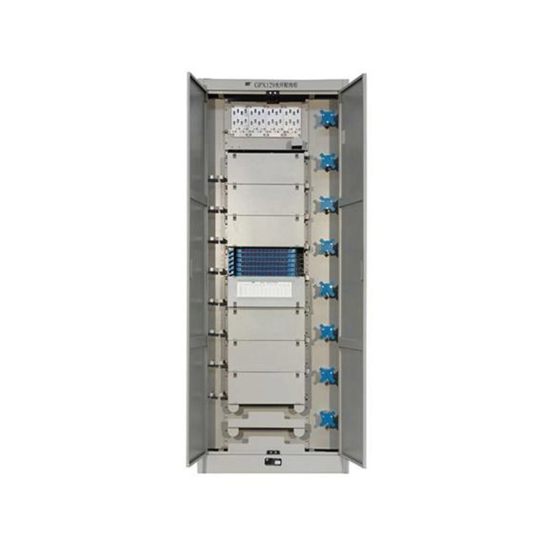
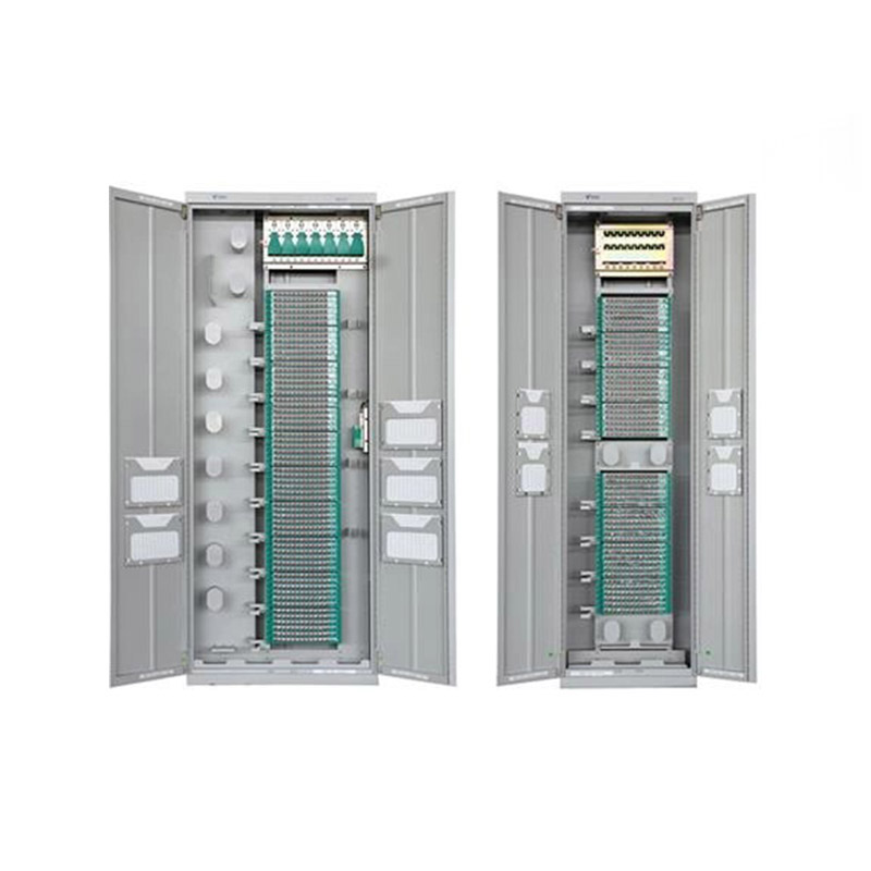
Application ScopeThe GPX129BKC fiber optic distribution frame is used to connect and distribute optical cables to optical communication equipment, and is suitable for large-capacity fiber optic commun...
See Details -
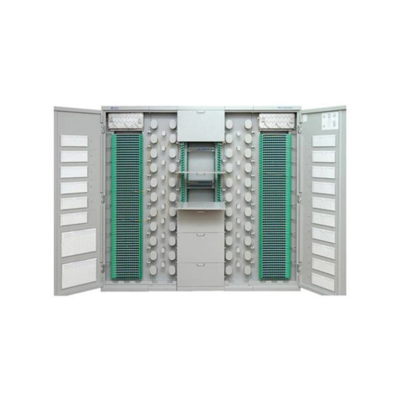
Application Used in FTTH network access-layer equipment rooms where splitting, splicing, distribution and other operations need to be carried out within a frame. Used in FTTH networks where optical sp...
See Details -
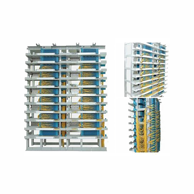
Application Used in independent fiber patching areas of newly built communication equipment rooms and central equipment rooms. After cable removal, the original main distribution frame is dismantled, ...
See Details
Ready to Get started ? Contact Us Now !

Product.
Contact Details.
-
 +86 13958188250
-
 +86 13958188250
-
 [email protected]
-
 AUDIT Email:[email protected]
- Wanma Industrial Park Taihu Yuan Town Lin'an District Hangzhou City China.
QR Code

Copyright © Wanma Technology Co., Ltd. All Rights Reserved.
Privacy
Custom Ethernet Optical Network Railway Transit Equipments Suppliers
