

 English
 Français
 Español
 Português
 عربى



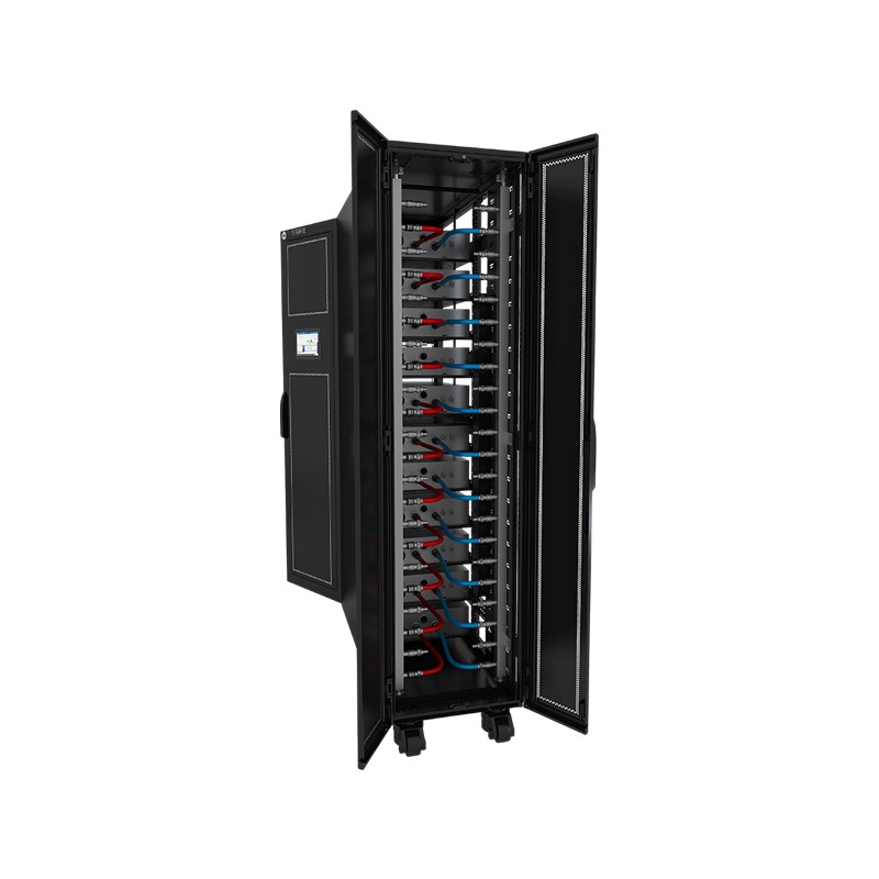
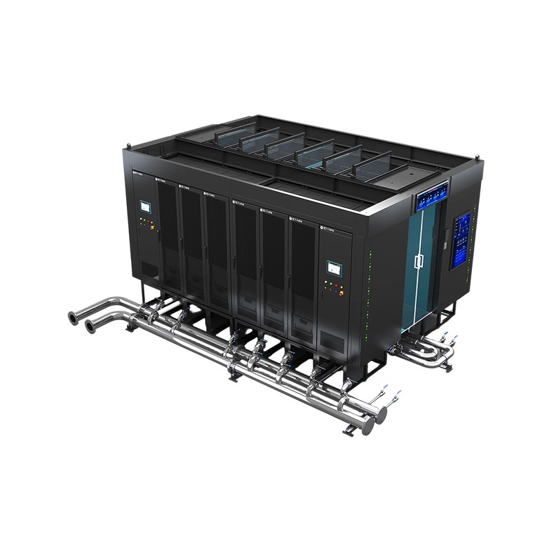
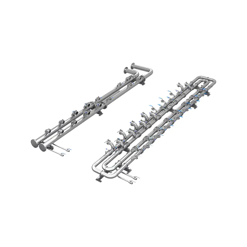

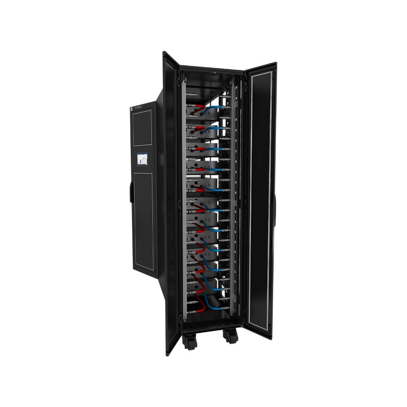
Product OverviewWM-LCR Liquid-Cooled Server Cabinet is a dedicated data center cabinet system that uses liquid as the cooling medium. Through circulating coolant, it efficiently transfers heat generat...
See DetailsIntegrated Liquid-Cooled Cabinet: High-Density Infrastructure for Next-Generation Data Centers
Content
- 1 1. Why High-Density Computing Requires Liquid Cooling
- 2 2. Product Architecture and Integrated Design
- 3 3. Core Technical Specifications
- 4 4. Cooling Capacity for AI and High-Performance Computing
- 5 5. Advantages over Conventional Air-Cooled Cabinets
- 6 6. Manifolds, Connectors, and Liquid Distribution
- 7 7. Protection, Redundancy, and Operational Safety
- 8 8. Power Distribution for Dense Equipment
- 9 9. Manufacturing and Engineering Strengths
- 10 10. Competitive Advantages in Practical Deployment
- 11 11. Applications
- 12 12. Installation and Commissioning Considerations
- 13 13. Maintenance and Lifecycle Management
- 14 14. Sustainability and Energy Considerations
- 15 15. Engineering Selection Guidelines
- 16 16. Why Manufacturer Integration Matters
- 17 17. Questions and Answers
- 17.1 What is an integrated liquid-cooled cabinet?
- 17.2 What is the cooling capacity of the cabinet?
- 17.3 How much equipment can the cabinet hold?
- 17.4 What coolant options are supported?
- 17.5 Does the system include pump redundancy?
- 17.6 How is liquid supplied to the cabinet?
- 17.7 What connector sizes are available?
- 17.8 Does the cabinet include leakage detection?
- 17.9 What communication protocols does the CDU support?
- 17.10 What type of power distribution is provided?
- 17.11 Can the cabinet be used in modular or containerized data centers?
- 17.12 Is the cabinet suitable for AI servers?
- 17.13 What makes the product different from a conventional air-cooled rack?
- 18 18. Conclusion
- 19 References
- 20 Product: Integrated Liquid-Cooled Cabinet
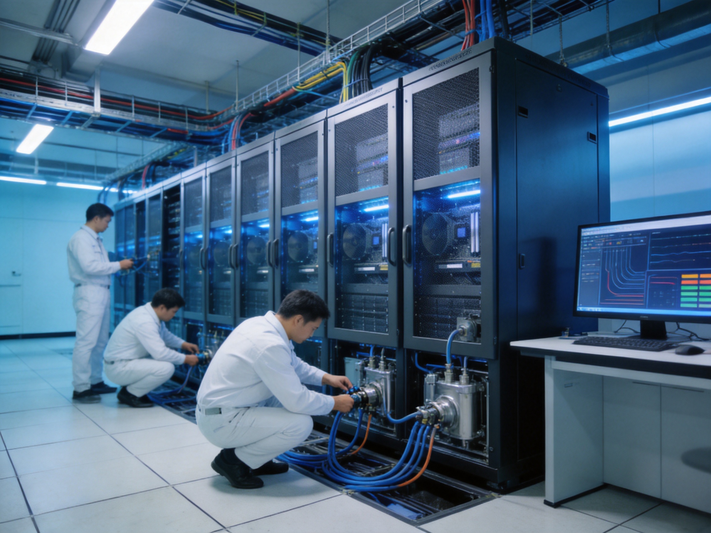
Modern data centers are entering an era in which computing density is increasing faster than conventional cooling infrastructure can adapt. Artificial intelligence servers, high-performance computing nodes, accelerated computing platforms, and other power-intensive systems generate substantial heat within a relatively small cabinet footprint. As rack power rises from traditional levels into the tens or even hundreds of kilowatts, air-based cooling becomes increasingly difficult to operate efficiently, economically, and reliably.
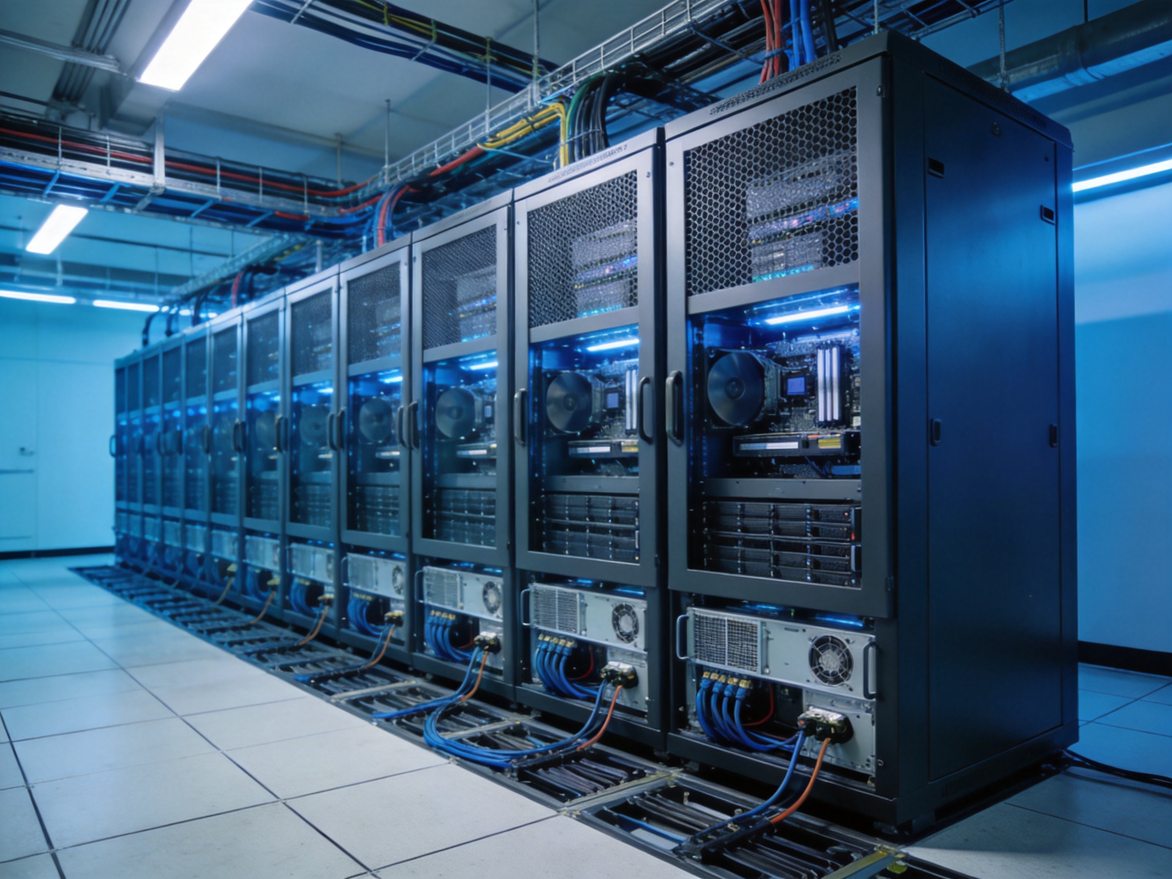
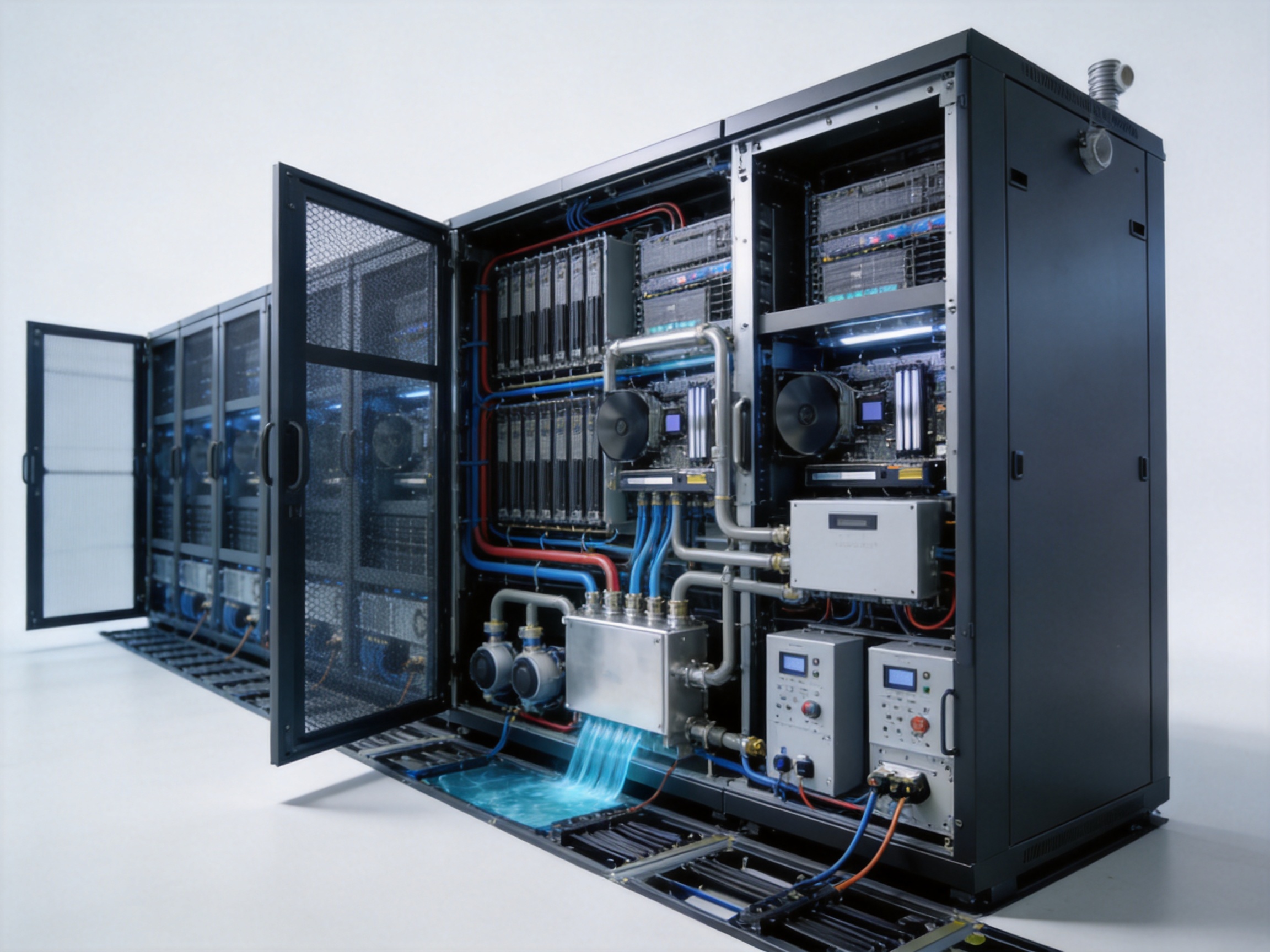
The integrated liquid-cooled cabinet is designed to address this challenge. It combines a high-capacity cabinet, liquid distribution components, a coolant distribution unit, power distribution units, quick connectors, hoses, monitoring provisions, and cabinet-level leakage detection in a coordinated platform. Instead of depending primarily on room air to remove heat, the system transfers heat through liquid, enabling a more direct and efficient thermal-management method for high-density computing environments.
With a nominal cooling capacity of up to 120 kW at 4°C approach temperature difference, the cabinet is suitable for demanding applications such as artificial intelligence clusters, high-performance computing installations, modular data centers, containerized data centers, edge computing rooms, and specialized equipment rooms. Its integrated design also helps reduce the complexity associated with combining cabinets, cooling units, manifolds, power systems, and monitoring devices from multiple suppliers.
This article examines the product’s architecture, operating principles, technical specifications, advantages over conventional alternatives, safety provisions, deployment considerations, and the manufacturing and solution capabilities behind its development.
1. Why High-Density Computing Requires Liquid Cooling
Traditional data-center cooling systems are generally designed around the movement of conditioned air. Computer room air-conditioning units, in-row coolers, raised-floor systems, containment structures, fans, and heat exchangers work together to circulate air through the equipment and return heated air to the cooling plant. This approach remains effective for many conventional IT environments, particularly where rack power density is moderate and heat is distributed across a relatively large space.
However, the thermal behavior of modern computing equipment is changing. AI accelerators and high-performance processors concentrate more electrical power in fewer servers. A single rack may contain multiple systems with high thermal design power, while the physical dimensions of the equipment remain similar to those of conventional servers. As a result, the heat generated per cabinet increases significantly.
Air has a relatively low heat capacity and low density compared with liquid. Removing a large amount of heat through air therefore requires high airflow volumes, large fans, extensive ducting, powerful room cooling equipment, and carefully managed air paths. These requirements can lead to several practical limitations:
First, the available airflow through server chassis and rack spaces may become insufficient. Even when room-level cooling equipment has adequate total capacity, individual servers may not receive enough cool air at the required temperature and flow rate.
Second, increased fan activity raises energy consumption and acoustic output. Servers may increase their internal fan speeds to protect processors, memory modules, and accelerators, while room cooling equipment must also work harder to maintain the desired environmental conditions.
Third, airflow distribution becomes more difficult as rack density rises. Hot spots may occur inside a cabinet or between adjacent cabinets, even when average room temperature appears acceptable.
Fourth, adding more air-conditioning units or expanding room airflow infrastructure may require substantial floor space, structural modifications, and electrical capacity. These changes can increase project cost and extend deployment schedules.
Liquid cooling addresses these limitations by bringing the cooling medium closer to the heat source. Depending on the server design, liquid may be delivered to cold plates, rear-door heat exchangers, immersion systems, or other heat-transfer devices. In the integrated liquid-cooled cabinet, the cabinet-level infrastructure supports the circulation and management of liquid through a controlled secondary-side circuit.
Because liquid can transport significantly more heat within a smaller flow volume, a liquid-cooled system can serve high-power racks without relying exclusively on massive room airflow. This makes it especially valuable for high-density deployments where conventional air cooling would require excessive energy, space, or equipment complexity.
2. Product Architecture and Integrated Design
The integrated liquid-cooled cabinet is more than a standard equipment enclosure with a cooling accessory. It is a coordinated infrastructure platform that combines mechanical support, liquid distribution, power management, control, and protection within one cabinet-level solution.
The main cabinet is available in heights of 2000 mm or 2200 mm, a width of 600 mm, and a depth of 1200 mm. Depending on the selected height, the usable installation capacity is 40U or 44U. This format is compatible with the familiar rack-based architecture used for servers, networking equipment, storage systems, power electronics, and other data-center hardware.
The cabinet is designed for a load capacity of up to 1000 kg. It is also specified for seismic grades 8 and 9, supporting deployment in locations where enhanced structural resistance is important. The combination of high load-bearing performance and seismic design makes the cabinet suitable for equipment configurations containing dense servers, liquid-cooling hardware, power distribution assemblies, and associated accessories.
Water is supplied from beneath the cabinet. Under-cabinet water supply helps preserve the upper cabinet area for equipment installation and creates a practical route for connecting the cabinet to facility-level cooling infrastructure. This arrangement can also support cleaner row layouts and reduce interference with overhead cable pathways.
The integrated architecture includes a coolant distribution unit, or CDU. The CDU manages the circulation of coolant between the facility cooling loop and the secondary-side equipment loop. Its nominal cooling capacity is 120 kW at a 4°C approach temperature difference, providing the thermal capacity required by demanding high-density applications.
The CDU includes a design flow rate of 140 liters per minute with an external residual pressure of 1.1 bar. The primary-side coolant may be pure water or an ethylene glycol solution. The secondary-side coolant may be pure water or a propylene glycol solution. Separating the primary and secondary circuits allows the system to manage different fluid requirements and helps isolate IT equipment from conditions in the facility-side cooling loop.
The secondary-side supply liquid temperature is specified at 10°C to 50°C with dew-point control. Dew-point management is essential in liquid cooling because condensation must be prevented on components, connectors, tubing, or other surfaces operating below the ambient dew point. A controlled supply temperature provides flexibility for different operating conditions while maintaining attention to moisture risk.
The CDU has 1+1 pump redundancy. If one pump is unavailable, the redundant pump can support continued operation, subject to system controls and operating conditions. Redundant pumping is particularly important in high-availability computing environments where a single pump failure should not immediately interrupt cooling circulation.
The CDU contains 8.2 liters of secondary-side water capacity and has a rated power of 990 W. Its dimensions are 445 mm by 850 mm by 176 mm, with a dry weight of 71.0 kg. The power supply accepts 100 to 240 VAC at 50 or 60 Hz and includes 1+1 power-supply redundancy.
For management and integration, the CDU supports Modbus, SNMP, and Web communication protocols. These interfaces make it possible to connect cooling information to building management systems, data-center infrastructure management platforms, supervisory control systems, or local operational dashboards.
3. Core Technical Specifications
The following table summarizes the principal specifications supplied for the integrated liquid-cooled cabinet and its associated cooling, power, manifold, and monitoring assemblies.
| System Area | Item | Specification |
|---|---|---|
| Cabinet | Cabinet size | 2000 or 2200 mm high × 600 mm wide × 1200 mm deep |
| Cabinet | Available installation space | 40U or 44U |
| Cabinet | Load and seismic performance | Up to 1000 kg load capacity; seismic grades 8 and 9 |
| Water connection | Water inlet method | Under-cabinet water supply |
| CDU | Nominal cooling capacity | 120 kW at 4°C ATD |
| CDU | Design flow rate | 140 LPM with 1.1 bar external residual pressure |
| CDU | Primary-side coolant | Pure water or ethylene glycol solution |
| CDU | Secondary-side coolant | Pure water or propylene glycol solution |
| CDU | Pump arrangement | 1+1 redundancy |
| CDU | Secondary-side supply temperature | 10°C to 50°C with dew-point control |
| CDU | Communication | Modbus, SNMP, and Web |
| PDU | Quantity | Two units |
| PDU | Rated current | 80 A |
| PDU | Rated voltage | 380 VAC |
| PDU | Maximum power | 52,800 W |
| PDU | Outlet configuration | Six C13 anti-drip outlets and twelve C19 anti-drip outlets |
| Manifold | Quantity | Two units |
| Manifold | Main interface | 50.5 mm quick disc coupling |
| Manifold | Branch interface | UDQ04 with 12 branches |
| Manifold | Construction | 40 × 40 mm stainless-steel square tube; total length 1920 mm including exhaust valve |
| Quick connector | Standard and options | UDQ04 standard; UDQ06 and UDQ08 optional |
| Hose | EPDM hose | UL94 V0 flame-retardant certified; optional red and blue color differentiation |
| Monitoring | Cabinet sensor | Leakage sensor |
| Monitoring | Environmental monitoring system | Optional |
4. Cooling Capacity for AI and High-Performance Computing
The most important performance characteristic of a high-density liquid-cooled cabinet is its ability to manage concentrated thermal loads. A 120 kW nominal cooling capacity allows the platform to support a substantial amount of IT heat within a single cabinet-level system.
Actual usable capacity depends on several factors, including the temperature difference between the facility-side and secondary-side circuits, coolant properties, flow resistance, server cold-plate design, ambient conditions, control settings, and the heat load profile. Nevertheless, the specified capacity places the cabinet in a class intended for high-power computing rather than ordinary low-density server deployment.
For AI workloads, thermal demand may vary rapidly as accelerators move between training, inference, data preparation, and idle states. The cooling system must therefore provide sufficient capacity not only for average consumption but also for high-load operating periods. The CDU’s controlled circulation and communication interfaces support monitoring of changing thermal conditions and allow operators to integrate cooling data with wider infrastructure-management systems.
High-performance computing environments present a similar challenge. Scientific simulation, engineering analysis, financial modeling, rendering, and research workloads can operate processors and accelerators at sustained high utilization. In these applications, the cooling system must support continuous operation while minimizing the risk of thermal throttling.
Liquid cooling can also help maintain more stable inlet temperatures at the equipment level. Stable thermal conditions may contribute to predictable system performance and reduce the need for aggressive server fan operation. This does not eliminate all airflow requirements, because some components may remain air-cooled, but it can significantly reduce the burden placed on room-level air-conditioning systems.
5. Advantages over Conventional Air-Cooled Cabinets
Higher heat-removal efficiency
The principal advantage of liquid cooling is the heat-transfer capability of the coolant. Compared with air, liquid can transport a greater amount of heat through a smaller physical flow path. The supplied product description indicates that liquid-cooled racks can achieve cooling efficiency dozens of times higher than traditional air-cooled racks in suitable applications.
This advantage becomes more meaningful as rack power increases. Conventional air cooling may be sufficient at moderate densities, but the required airflow, fan power, and room-cooling capacity rise sharply when the rack contains many high-power processors. Liquid cooling provides a more direct path from the heat source to the heat exchanger or facility cooling loop.
Support for higher rack density
The cabinet is designed for high-density equipment with power requirements ranging from tens of kilowatts toward hundreds of kilowatts. Its 40U or 44U capacity allows substantial computing equipment to be installed in a standard rack footprint while the integrated liquid infrastructure manages the associated thermal load.
Higher density can help data-center operators use floor space more effectively. Instead of distributing computing equipment across many lower-power cabinets, operators may be able to consolidate selected workloads into fewer high-capacity cabinets. The practical outcome depends on server design, power availability, facility cooling capacity, and deployment policies, but the cabinet is built around this high-density operating model.
Reduced dependence on room airflow
Liquid cooling can reduce the amount of heat that must be removed through room air. This may lower the required airflow volume, reduce hot-aisle and cold-aisle pressure, and simplify the design of cooling zones. It can also reduce the need for oversized room air-conditioning systems in applications where a large portion of the IT heat is captured by the liquid circuit.
Reduced airflow demand may provide further benefits, including lower fan energy consumption, reduced acoustic output, and more flexible equipment placement. However, room ventilation and residual air cooling must still be designed according to the specific equipment configuration.
Integrated power and cooling coordination
A major difference between this product and a basic liquid-cooling add-on is the inclusion of two 80 A, 380 VAC PDUs with a maximum power rating of 52,800 W and a defined outlet arrangement. The power and cooling functions are considered together at cabinet level rather than treated as entirely separate infrastructure projects.
The two PDU units provide 6 C13 anti-drip outlets and 12 C19 anti-drip outlets. This combination supports different equipment power-cord requirements and provides a practical distribution structure for server and networking hardware. Anti-drip outlet construction is particularly relevant in a cabinet containing liquid circuits, because it adds a protective design consideration around electrical connection points.
Improved deployment consistency
When a data-center operator combines a standard cabinet, a separately selected CDU, third-party manifolds, independently sourced hoses, and unrelated monitoring equipment, compatibility and responsibility can become unclear. An integrated cabinet reduces the number of interfaces that must be engineered during installation.
The cabinet, CDU, manifolds, connectors, hoses, power distribution components, and leakage sensors are configured as part of one product concept. This can help standardize cabinet deployment across a room or modular data-center project. Standardization may also make documentation, training, maintenance planning, and spare-parts management more straightforward.
6. Manifolds, Connectors, and Liquid Distribution
Reliable liquid distribution is essential because the performance of the cooling system depends not only on the CDU but also on the quality and consistency of coolant delivery to individual devices.
The integrated cabinet includes two manifolds. The main inlet and outlet interface uses a 50.5 mm quick disc coupling, while the branch interface uses UDQ04 with 12 branches. This arrangement enables multiple liquid-cooled devices or cooling branches to be connected within a cabinet configuration.
The manifolds are constructed from 40 × 40 mm stainless-steel square tube and have a total length of 1920 mm, including an exhaust valve. Stainless steel provides a robust material choice for a liquid distribution assembly, particularly where mechanical strength, dimensional stability, and resistance to the operating environment are important.
An exhaust valve supports air removal during filling and commissioning. Air trapped in a liquid circuit can reduce flow stability, create noise, affect pump operation, and reduce heat-transfer performance. A properly designed exhaust function helps technicians purge the system during installation and maintenance.
The standard quick connector is UDQ04, with UDQ06 and UDQ08 available as options. Offering connector alternatives allows the liquid interface to be matched to different server-side requirements and hose sizes. Quick-disconnect technology can simplify installation and service, provided that the connectors are correctly selected, fully engaged, inspected, and operated according to applicable procedures.
The system uses EPDM hoses with UL94 V0 flame-retardant certification. Red and blue color differentiation is available as an option. Color coding can help installers and maintenance personnel distinguish supply and return paths, reduce connection errors, and improve visual identification during inspection.
In a liquid-cooled data center, hoses should be routed with appropriate bend radii and mechanical support. They should not be placed where they can be crushed by equipment, exposed to sharp edges, or subjected to unnecessary tensile loads. The integrated cabinet design helps establish an organized connection area, but final installation quality remains important to long-term reliability.
7. Protection, Redundancy, and Operational Safety
Liquid near electrical and electronic equipment requires a disciplined approach to safety. The integrated liquid-cooled cabinet includes a cabinet leakage sensor to detect the presence of unwanted liquid. This sensor provides an important first layer of protection by alerting operators to a potential leak before it develops into a larger event.
An optional environmental monitoring system can extend the monitoring capability. Depending on the final configuration, environmental monitoring may be used to collect and report information such as cabinet temperature, humidity, liquid status, door status, or other relevant operating conditions. The exact sensor package should be confirmed for each project.
Leak detection should be connected to appropriate operational procedures. An alarm is most valuable when it is visible to responsible personnel, recorded in an infrastructure-management platform, and associated with a defined response plan. Operators should know how to isolate a branch, stop or reduce coolant flow, protect electrical equipment, and inspect the affected area.
The CDU’s 1+1 pump redundancy supports continuity in the event of a single pump fault. The 1+1 redundant power supply arrangement provides a similar principle on the electrical side of the CDU. The two PDUs can also support dual-corded equipment and power-path planning, subject to the facility’s upstream electrical architecture.
Redundancy does not mean that every failure scenario is eliminated. The complete system should be evaluated for facility pump failure, loss of primary cooling, power interruption, control-system malfunction, connector failure, hose degradation, sensor failure, and human error. Even so, redundant components can reduce the likelihood that a single component fault will immediately interrupt cooling service.
Dew-point control is another important safety feature. If the coolant temperature is lower than the surrounding air’s dew point, condensation may form on cold surfaces. The specified secondary-side supply temperature range of 10°C to 50°C, combined with dew-point control, supports a more disciplined operating strategy. Facility designers should still calculate local humidity conditions and establish alarm thresholds appropriate to the deployment environment.
8. Power Distribution for Dense Equipment
High-density cooling must be matched by high-density power distribution. A cabinet that can remove substantial heat but cannot safely deliver adequate electrical power would not meet the requirements of AI or high-performance computing equipment.
The product includes two PDUs, each with a rated current of 80 A and a rated voltage of 380 VAC. The stated maximum power is 52,800 W. The PDU arrangement is intended to support dense rack equipment while providing a structured method for distributing power to servers, switches, storage systems, and other devices.
The outlet layout includes six C13 anti-drip outlets and twelve C19 anti-drip outlets. C13 outlets are commonly used for lower-power IT devices, while C19 outlets are suited to equipment requiring higher current capacity. The combination helps accommodate different equipment types within the same cabinet.
Power planning should consider the difference between nominal, rated, and actual operating power. The maximum PDU rating is not necessarily the recommended continuous operating level for every installation. Designers should account for upstream circuit protection, phase balancing, equipment inrush current, cable sizing, ambient conditions, redundancy requirements, and local electrical regulations.
The cabinet’s power architecture is especially useful when deployed with dual-corded servers. One cord may be connected to each PDU, allowing the equipment to remain powered if one distribution path is unavailable. The effectiveness of this arrangement depends on independent upstream sources and properly coordinated protection devices.
The integration of power and cooling also supports better planning for total cabinet capacity. Electrical power consumed by IT equipment is ultimately converted into heat. By reviewing the maximum electrical load alongside the 120 kW CDU capacity, project engineers can evaluate whether the selected cooling and power systems are appropriately sized for the intended equipment population.
9. Manufacturing and Engineering Strengths
The product is supplied by Wanma Technology Co., Ltd., a company established in 1997 with experience in communication cabinets, communication electronic equipment, and passive optical components. Its product portfolio is used in Ethernet networks, optical communication networks, central equipment rooms, national high-speed railways, and urban rail transit systems.
This background is relevant to liquid-cooled cabinet manufacturing because communication and data-center infrastructure demands consistent enclosure construction, organized cable and equipment management, mechanical reliability, and long-term field serviceability. Experience with communication cabinets provides a foundation for designing rack systems that must accommodate dense equipment while maintaining structural stability and installation discipline.
The company develops, manufactures, and markets its own branded products while also providing integrated solutions for customized products. This combination can be valuable for customers whose requirements do not fit a standard catalogue configuration. A project may require a different rack height, connector arrangement, monitoring package, power configuration, coolant interface, or cabinet layout. A manufacturer capable of integrating customized requirements can reduce the need for multiple external engineering parties.
Advanced manufacturing in this context is not limited to the production of individual parts. It includes requirements analysis, mechanical design, material selection, assembly control, liquid-path verification, electrical integration, functional testing, documentation, packaging, and after-sales support.
For the cabinet structure, manufacturing quality begins with accurate fabrication of the frame, panels, mounting rails, doors, and support members. Dimensional consistency is important because a small alignment error can affect equipment installation, manifold positioning, hose routing, or service access. High load capacity also requires attention to joints, mounting points, base construction, and load distribution.
The stainless-steel manifold requires controlled cutting, forming, joining, surface treatment, and inspection. Its 40 × 40 mm square-tube construction and defined 1920 mm length must be maintained so that branch connections align with the intended cabinet layout. The exhaust valve must remain accessible and properly sealed after assembly.
Liquid-system assembly requires additional process discipline compared with a conventional dry cabinet. Tubing, connectors, valves, pumps, reservoirs or water capacity, and heat exchangers must be assembled without introducing contaminants or damaging sealing surfaces. Components should be inspected for correct orientation, torque, fit, and compatibility with the selected coolant.
Pressure and leakage verification are essential manufacturing and quality-control activities for a liquid-cooled product. A finished assembly should be checked according to an established test procedure before shipment. Such procedures may include visual inspection, pressure holding, flow verification, sensor checks, alarm simulation, and functional validation of the pump and control system. The precise factory test scope should be confirmed with the supplier for each project.
Electrical integration also requires systematic inspection. The PDUs, CDU power supplies, communication interfaces, protective components, cable routing, and grounding provisions must be assembled consistently. Functional tests should verify correct operation of the power distribution and control interfaces while maintaining separation between electrical and liquid paths.
The company’s long operating history and international sales network provide further support for project delivery. Wanma Technology serves customers in more than 20 countries and regions, including the United States, Australia, the United Kingdom, Italy, South Africa, and Ghana. International experience can help a supplier understand different project expectations, documentation requirements, logistics conditions, and customer support practices.
The company emphasizes reliable product quality, timely delivery, and long-term strategic partnerships. These strengths are important for data-center infrastructure because the purchase decision involves more than initial equipment cost. Operators also need predictable lead times, spare-parts availability, technical communication, commissioning assistance, and support throughout the service life of the installation.
10. Competitive Advantages in Practical Deployment
The integrated liquid-cooled cabinet competes with several alternative approaches: conventional air-cooled racks, air-cooled racks supplemented by rear-door heat exchangers, standalone liquid-cooling systems assembled from multiple vendors, and custom-built liquid-cooling enclosures.
Compared with ordinary air-cooled cabinets, the primary advantage is high-density thermal capacity. The cabinet is purpose-designed for liquid cooling and provides a 120 kW CDU, liquid manifolds, quick connectors, EPDM hoses, and leakage sensing. This avoids treating liquid cooling as an afterthought added to a cabinet originally designed only for airflow.
Compared with a fragmented multi-vendor solution, the integrated product can reduce interface risk. One supplier is responsible for coordinating the cabinet, CDU, manifolds, hoses, PDU arrangement, and monitoring provisions. This may simplify procurement, project management, troubleshooting, and warranty communication.
Compared with a purely custom-built system, the product benefits from a defined technical platform. The 40U and 44U cabinet options, standard UDQ04 connector, optional connector sizes, two-manifold arrangement, and established PDU configuration provide a starting point for faster project planning. Customization can then be applied where required rather than rebuilding the entire system from the beginning.
Compared with systems that provide only cooling hardware, the product includes supporting infrastructure for power and monitoring. The 80 A PDUs, C13 and C19 outlets, Modbus, SNMP, Web communication, leakage sensor, and optional environmental monitoring help create a more complete cabinet-level deployment.
Another advantage is the balance between density and familiar rack architecture. IT teams can continue using standard rack units and cabinet installation practices while gaining access to a liquid-based heat-removal system. This may reduce the training burden compared with adopting an entirely different computing enclosure format.
11. Applications
Artificial intelligence data centers
AI training and inference platforms frequently use accelerator-rich servers that generate high thermal loads. The integrated liquid-cooled cabinet can support the cooling and power infrastructure needed for such systems, particularly when multiple high-power servers are concentrated within a 40U or 44U cabinet.
High-performance computing
Research institutions, universities, engineering companies, laboratories, and financial organizations may operate computing clusters at sustained high utilization. Liquid cooling helps address the continuous heat output of dense processor and accelerator configurations while supporting controlled environmental conditions.
Modular and containerized data centers
Modular data centers often place a premium on compactness, repeatability, and predictable installation. The integrated cabinet can be incorporated into modular or containerized designs where floor area, airflow, and deployment time are limited. Under-cabinet water supply may also support organized modular utility routing.
Edge computing facilities
Edge locations may have limited room for large air-conditioning systems or may be located in environments with challenging thermal conditions. A cabinet-level liquid-cooling platform can help concentrate cooling capability near the high-density computing load, provided that the site has an appropriate primary cooling source and maintenance plan.
Telecommunications and network equipment rooms
Telecommunications facilities are increasingly supporting edge analytics, virtualized network functions, 5G applications, and localized computing. The manufacturer’s background in communication cabinets and electronic equipment is relevant to these environments, where rack organization, reliability, and integration with network infrastructure are important.
Railway and transportation systems
Railway transit systems and transportation control environments may require robust equipment infrastructure in central equipment rooms or specialized technical facilities. The cabinet’s structural design, high load capacity, seismic specifications, and monitoring options can be considered for applications that require enhanced mechanical stability and controlled equipment operation.
12. Installation and Commissioning Considerations
Successful deployment begins with a complete site survey. Engineers should verify floor loading, access routes, cabinet clearances, service space, water supply and return connections, drainage provisions, electrical capacity, grounding, network connectivity, ambient temperature, humidity, and fire-protection requirements.
The cabinet’s total equipment load should be calculated before installation. Although the specified load capacity is up to 1000 kg, the actual arrangement must distribute weight appropriately across the cabinet structure and floor. Heavy components such as the CDU and dense server assemblies should be installed according to the approved mechanical layout.
Primary-side and secondary-side coolant circuits should be designed with compatible materials and fluid properties. If glycol solutions are selected, the concentration should be determined according to the required freeze protection, heat-transfer performance, viscosity, pump capability, and manufacturer recommendations. Coolant quality should be controlled to reduce corrosion, scaling, biological growth, and contamination.
During filling, technicians should use the exhaust valve and follow an approved air-purging procedure. The circuit should be inspected for leaks before IT equipment is energized. Quick connectors should be checked for complete engagement, and hoses should be routed without sharp bends or mechanical stress.
The CDU control system should be connected to the intended monitoring network using Modbus, SNMP, or Web access as appropriate. Alarm points should be tested, including pump status, supply and return temperature, flow condition, leakage status, power supply status, and communication loss where supported by the final configuration.
Electrical commissioning should include verification of voltage, phase arrangement, current protection, grounding, outlet labeling, PDU redundancy, and equipment cord placement. The stated 380 VAC rated voltage and 80 A rated current should be evaluated against local electrical standards and the site’s distribution design.
The system should be commissioned under controlled load conditions before full production operation. Operators can progressively increase IT load while observing coolant temperature, flow rate, pump operation, cabinet temperature, electrical current, and alarm behavior. Baseline readings should be recorded for future maintenance and troubleshooting.
13. Maintenance and Lifecycle Management
Liquid-cooled infrastructure requires a maintenance program that covers both conventional rack components and fluid-handling equipment. Routine inspections should include hoses, quick connectors, manifold joints, valves, pump assemblies, electrical connections, sensors, filters if present, and cabinet surfaces.
Leakage sensors should be tested periodically to confirm that alarms reach the intended monitoring platform. A sensor that has never been tested may provide false confidence. Operators should also inspect the sensor location to ensure that it has not been obstructed or contaminated.
Pump redundancy should be verified through controlled testing. The maintenance team should understand how to transfer operation between the primary and redundant pump, how to interpret pump alarms, and how to replace a failed unit without exposing equipment to unnecessary risk.
Coolant condition should be monitored according to the selected fluid and operating environment. Water quality, glycol concentration, contamination, corrosion indicators, and biological control may all be relevant. The maintenance interval should be based on the system design, coolant supplier guidance, operating hours, and site conditions.
Air may gradually accumulate in a liquid circuit after maintenance or component replacement. The exhaust valve and commissioning procedure should be used to remove trapped air. Abnormal noise, fluctuating flow, unexpected temperature differences, or unstable pump performance may indicate the need for inspection.
Power distribution should be reviewed as IT equipment changes. New servers and accelerators may have different current characteristics from the original equipment. PDU load, phase balance, outlet condition, cable temperature, and redundancy should be checked after major equipment upgrades.
Firmware and software maintenance may also be necessary for the CDU’s monitoring and communication functions. Modbus registers, SNMP settings, user access, network security, and alarm destinations should be documented and controlled as part of the data-center operations process.
14. Sustainability and Energy Considerations
Energy efficiency is a major consideration in modern data-center design. Cooling energy can represent a significant portion of total facility consumption, especially when high-density computing is supported by large air-conditioning systems and extensive fan operation.
Liquid cooling can improve the ratio between heat removed and energy consumed by reducing the amount of air that must be moved and conditioned. The actual energy benefit depends on the facility cooling architecture, coolant temperature, pump efficiency, heat exchanger performance, control strategy, and IT workload.
The ability to operate at suitable liquid temperatures may also support more efficient heat rejection in some climates and facility configurations. Dew-point control remains essential, but a carefully designed system may reduce dependence on very low room supply-air temperatures.
Liquid cooling may also support heat reuse opportunities. In certain facilities, the warm secondary-side coolant could be connected to a heat-recovery system for building heating, industrial processes, or other useful applications. Such projects require detailed thermal, regulatory, and economic analysis, but the liquid circuit provides a more accessible heat-transfer path than exhaust air.
Sustainability should also be evaluated across the product lifecycle. Durable cabinet materials, replaceable pumps, standardized quick connectors, serviceable manifolds, and documented maintenance procedures can help extend equipment life. A longer service life may reduce replacement frequency and associated material consumption.
15. Engineering Selection Guidelines
Before selecting the cabinet, the customer should create an equipment heat-load schedule. The schedule should identify the number of servers, accelerator modules, switches, storage units, and other devices; their maximum and typical power consumption; their liquid-cooling requirements; and their connector specifications.
The total IT heat load should be compared with the CDU’s 120 kW nominal cooling capacity. Engineers should include appropriate design margin and should not assume that nameplate capacity is equivalent to unrestricted continuous capacity under every operating condition.
The required flow rate should be evaluated at the device level and at the cabinet level. The CDU design flow rate is 140 LPM under the stated external residual-pressure condition. Pressure losses through manifolds, hoses, quick connectors, cold plates, filters, valves, and facility piping should be included in the hydraulic calculation.
Coolant compatibility must be confirmed for every wetted component. Pure water, ethylene glycol solutions, and propylene glycol solutions have different thermal, viscosity, corrosion, and material-compatibility characteristics. The primary and secondary circuits should be treated according to their separate design requirements.
Connector selection should be finalized before procurement. UDQ04 is the default connector, while UDQ06 and UDQ08 are optional. The selected connector must match the server-side interface, flow requirement, pressure rating, maintenance procedure, and available hose size.
Power demand should be evaluated separately from cooling demand, even though the two are closely related. The PDU maximum power of 52,800 W should be checked against the real equipment load, redundancy strategy, upstream electrical capacity, and local code requirements.
Environmental monitoring should be selected according to the operational risk profile. A basic installation may require leakage detection and CDU communications, while a critical facility may benefit from a more extensive environmental monitoring package and integration with a centralized data-center management platform.
16. Why Manufacturer Integration Matters
Liquid cooling involves mechanical, hydraulic, electrical, electronic, and software disciplines. A supplier that understands only one of these areas may leave the customer responsible for coordinating the remaining interfaces.
A manufacturer with experience in communication cabinets and electronic equipment can approach the product as a complete infrastructure unit. Cabinet dimensions, rack compatibility, cable management, power distribution, liquid routing, monitoring, and service access can be designed together rather than optimized in isolation.
Wanma Technology’s history since 1997 demonstrates long-term involvement in infrastructure products rather than a short-term entry into the equipment market. Its experience in Ethernet networks, optical communications, central equipment rooms, railways, and urban rail transit systems provides exposure to applications in which reliability, organized installation, and long operational life are important.
The company’s ability to develop and manufacture its own products also supports greater control over product evolution. When customers identify new requirements, a manufacturer with internal product-development capabilities may be able to adapt cabinet configurations, interfaces, monitoring options, and integrated solutions more efficiently than a reseller dependent entirely on unrelated third parties.
Its international sales coverage across more than 20 countries and regions further supports global project engagement. Customers working across multiple markets may benefit from a supplier that has experience coordinating export products, international customer communication, and long-term commercial relationships.
These strengths should be evaluated together with project-specific evidence, including drawings, test reports, quality procedures, warranty terms, installation guidance, spare-parts plans, and references appropriate to the intended application.
17. Questions and Answers
What is an integrated liquid-cooled cabinet?
An integrated liquid-cooled cabinet is a rack enclosure that combines IT equipment mounting space with liquid-cooling infrastructure, power distribution, liquid manifolds, connectors, hoses, monitoring, and protection features. It is designed for high-density equipment that produces more heat than conventional air-cooled cabinets can efficiently manage.
What is the cooling capacity of the cabinet?
The associated CDU has a nominal cooling capacity of 120 kW at a 4°C approach temperature difference. Actual operating capacity depends on coolant temperature, flow rate, facility conditions, equipment requirements, and the final system design.
How much equipment can the cabinet hold?
The cabinet is available with 40U or 44U of usable installation space. Its stated load capacity is up to 1000 kg. The final equipment arrangement should be checked for rack-unit availability, weight distribution, power demand, cooling demand, and service access.
What coolant options are supported?
The primary side supports pure water or an ethylene glycol solution. The secondary side supports pure water or a propylene glycol solution. The selected coolant must be compatible with all wetted materials and should be managed according to the supplier’s operating recommendations.
Does the system include pump redundancy?
Yes. The CDU uses a 1+1 redundant pump arrangement. The CDU power supply also uses 1+1 redundancy. These features are intended to improve operational continuity in the event of a single component or power-supply fault.
How is liquid supplied to the cabinet?
The water inlet method is under-cabinet water supply. The cabinet includes two manifolds, a 50.5 mm quick disc coupling for the main inlet and outlet interface, and UDQ04 branch interfaces with 12 branches.
What connector sizes are available?
UDQ04 is the default quick connector. UDQ06 and UDQ08 are available as optional selections. The correct connector should be chosen according to the server-side interface and required flow capacity.
Does the cabinet include leakage detection?
Yes. A cabinet leakage sensor is included. An environmental monitoring system is also available as an optional feature. The final alarm and monitoring architecture should be confirmed during project engineering.
What communication protocols does the CDU support?
The CDU supports Modbus, SNMP, and Web communication. These interfaces can be used for local supervision or integration with data-center infrastructure management and building-management platforms.
What type of power distribution is provided?
The cabinet includes two PDUs. The specified rating is 80 A at 380 VAC, with a maximum power of 52,800 W. The outlet arrangement includes six C13 anti-drip outlets and twelve C19 anti-drip outlets.
Can the cabinet be used in modular or containerized data centers?
Yes. The product is intended for applications including modular and containerized data centers. The suitability of a specific deployment depends on structural loading, utility connections, environmental conditions, fire protection, transport requirements, and maintenance access.
Is the cabinet suitable for AI servers?
It is designed for high-density, high-power IT equipment such as AI servers and high-performance computing nodes. The final suitability should be verified against the specific server’s liquid interface, coolant requirements, power consumption, heat load, and rack dimensions.
What makes the product different from a conventional air-cooled rack?
It uses liquid as the primary cooling medium and integrates a 120 kW CDU, liquid manifolds, quick connectors, hoses, leakage sensing, redundant pumping, and high-capacity power distribution. This makes it better suited to concentrated heat loads than a standard cabinet that relies mainly on room airflow.
18. Conclusion
The integrated liquid-cooled cabinet provides a structured response to the rising thermal and electrical demands of AI, high-performance computing, telecommunications, and next-generation data-center infrastructure. Its 40U and 44U cabinet formats, 1000 kg load capacity, seismic grades 8 and 9, 120 kW CDU, 140 LPM design flow rate, redundant pumps, dual PDUs, liquid manifolds, quick connectors, EPDM hoses, leakage sensor, and communication interfaces form a comprehensive cabinet-level platform.
Its main competitive advantage is integration. Instead of treating the cabinet, cooling distribution, power distribution, liquid connections, and monitoring as disconnected purchases, the product brings them together in a coordinated design. This can simplify deployment, reduce interface uncertainty, improve cabinet standardization, and support higher rack density than conventional air-cooling approaches.
The manufacturer adds value through its long-standing experience in communication cabinets, electronic equipment, passive optical components, railway infrastructure, rail transit systems, and network applications. Its ability to manufacture its own products and provide customized integrated solutions supports customers with specialized requirements and complex deployment environments.
As computing power continues to grow, liquid cooling is becoming an important foundation for efficient and reliable digital infrastructure. A carefully engineered integrated cabinet can help operators manage thermal density, protect critical equipment, organize power and liquid connections, and prepare their facilities for the next generation of computing workloads.
References
1. Product technical specification sheet for the integrated liquid-cooled cabinet, including cabinet, CDU, PDU, manifold, connector, hose, and monitoring data.
2. General principles of data-center thermal management and high-density computing infrastructure.
3. Engineering guidance for liquid-cooling distribution systems, coolant compatibility, flow management, and dew-point control.
4. UL 94, Standard for Tests for Flammability of Plastic Materials for Parts in Devices and Appliances.
5. General practices for rack power distribution, redundant power architectures, and data-center equipment installation.
6. General principles of Modbus, SNMP, and Web-based equipment monitoring integration.
7. Manufacturer background information concerning communication cabinets, optical communication products, railway transit applications, customized solutions, and international market service.
Product: Integrated Liquid-Cooled Cabinet
PREV:WM-2001-H10 Fiber Optic Splice Closure: Reliable Protection and Flexible Distribution for Modern Optical Networks
NEXT:High-Density 19-Inch Optical Distribution Frame for Reliable Fiber Management
NEXT:High-Density 19-Inch Optical Distribution Frame for Reliable Fiber Management
Interested in cooperation or have questions?
Related products
-
-
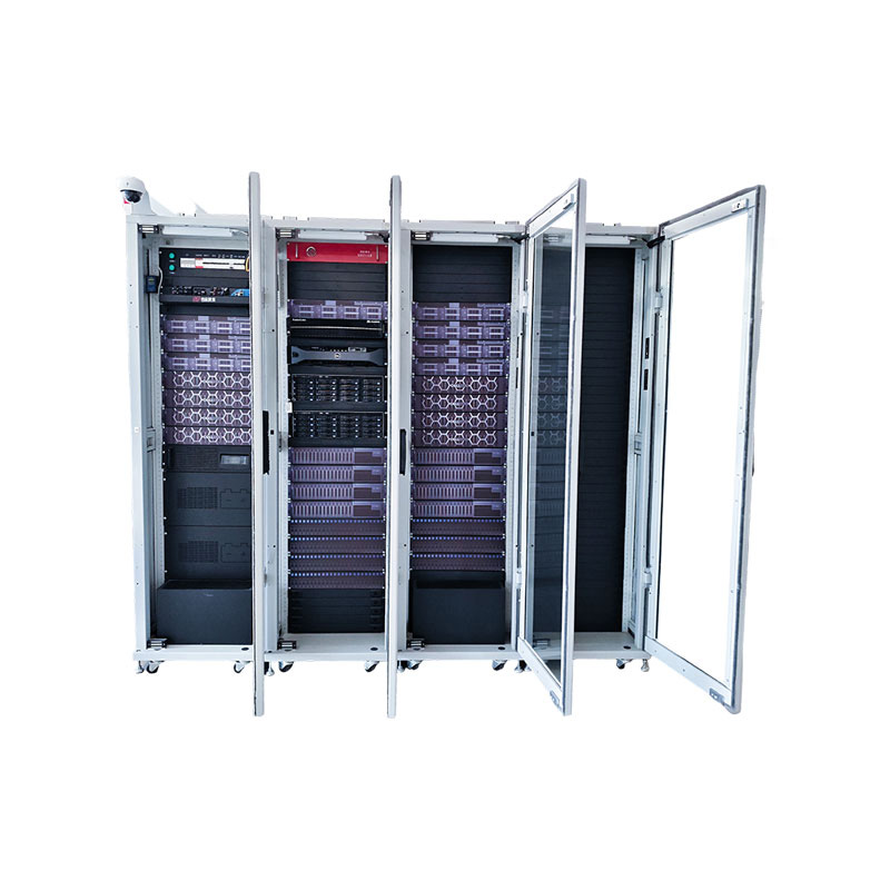
Product DefinitionThe Integrated Air-Cooled Cabinet adopts an "all-in-rack" design, deeply integrating cabinet structure, cooling, power distribution, cabling, and intelligent management subsystems to...
See Details -
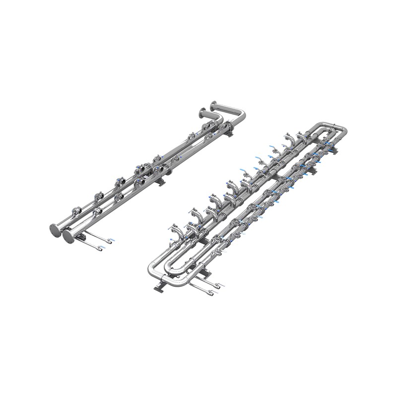
Product OverviewWM-SCL Secondary-Side Prefabricated Piping is a standardized coolant distribution system that connects the CDU to liquid-cooled server cabinets. The piping is prefabricated and quality...
See Details -
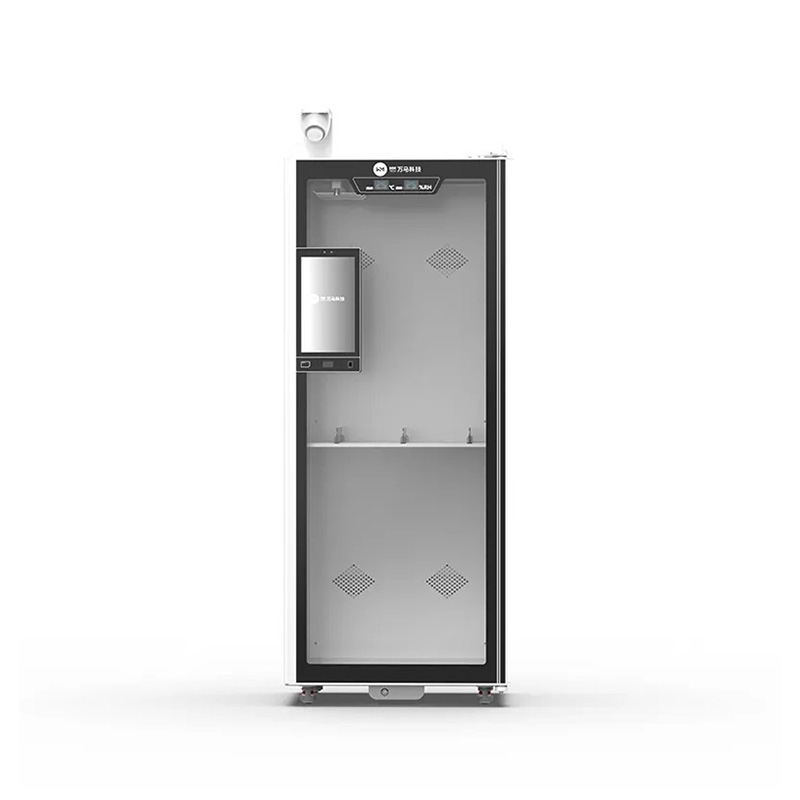
Product Definition This product is a high-capacity intelligent consumables management cabinet designed for hospitals, laboratories, and medical institutions, integrating RFID technology, smart access ...
See Details
Ready to Get started ? Contact Us Now !

Product.
Contact Details.
-
 +86 13958188250
-
 +86 13958188250
-
 [email protected]
-
 AUDIT Email:[email protected]
- Wanma Industrial Park Taihu Yuan Town Lin'an District Hangzhou City China.
QR Code

Copyright © Wanma Technology Co., Ltd. All Rights Reserved.
Privacy
Custom Ethernet Optical Network Railway Transit Equipments Suppliers
