

 English
 Français
 Español
 Português
 عربى






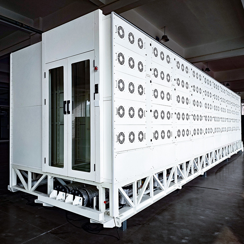
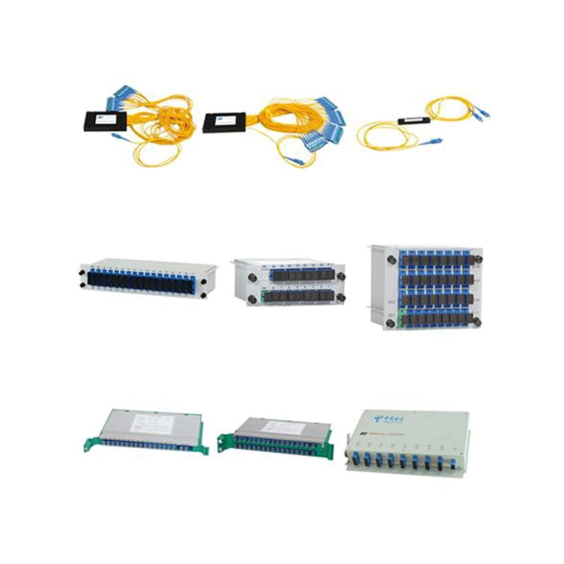

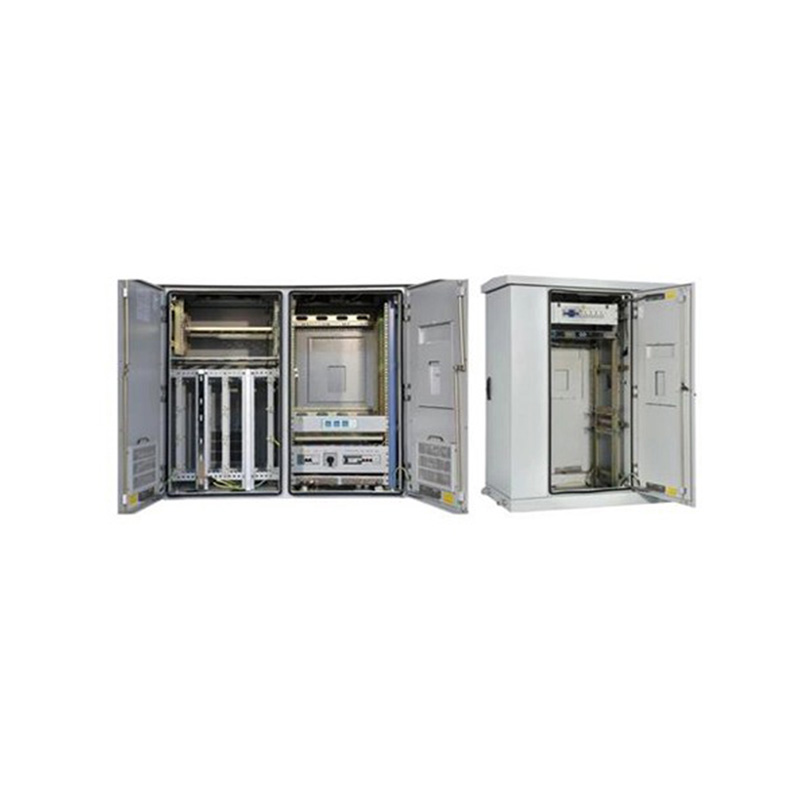
Application:It is used for the fixed network and broadband access, providing physical working environment and security system for the workstation in wired network. Features:•The cabinet is composed of...
See DetailsPrecision Fiber Interconnection Solutions for Modern Optical Networks
Content
- 1 1. The Role of Patch Cords, Pigtails, and Adaptors
- 2 2. Applications in Optical Distribution Equipment
- 3 3. High-Precision Ceramic Ferrules
- 4 4. Advanced End-Face Grinding and Polishing
- 5 5. Optical Performance Advantages
- 6 6. Mechanical and Environmental Reliability
- 7 7. Manufacturing Strengths and Process Control
- 8 8. Advantages Over Less Specialized Alternatives
- 9 9. Integration with Ethernet and 5G FTTH Modernization
- 10 10. Installation and Maintenance Considerations
- 11 11. Why Choose an Experienced Communication Equipment Manufacturer
- 12 12. Project Procurement Benefits
- 13 13. Quality, Reliability, and Long-Term Network Value
- 14 14. Recommended Selection Criteria
- 15 15. Q&A
- 15.1 Q1: What are patch cords, pigtails, and adaptors used for?
- 15.2 Q2: Where are these products commonly installed?
- 15.3 Q3: Why is the ceramic ferrule important?
- 15.4 Q4: What is insertion loss?
- 15.5 Q5: What is return loss?
- 15.6 Q6: Why are apex offset and curvature radius controlled?
- 15.7 Q7: Can the components be used for railway and urban rail transit networks?
- 15.8 Q8: How should connectors be maintained?
- 15.9 Q9: Can customized products be supplied?
- 15.10 Q10: What distinguishes a precision-manufactured component from a basic alternative?
- 15.11 Q11: Why is supplier experience important for passive optical products?
- 15.12 Q12: How can these products support future network expansion?
- 16 16. Conclusion
- 17 References
- 18 Product: Fiber Solution-Patch Cords, Pigtail, Adaptor

Reliable optical connectivity is the foundation of every high-performance fiber network. As communication systems expand from traditional telecom infrastructure to Ethernet access networks, railway transit communications, data centers, central equipment rooms, and 5G and FTTH modernization projects, the quality of each passive optical connection becomes increasingly important. Patch cords, pigtails, and adaptors may be compact components, but they have a direct influence on insertion loss, return loss, network stability, installation efficiency, and long-term maintenance.
The fiber solution consisting of patch cords, pigtails, and adaptors is designed for optical distribution equipment such as Optical Main Distribution Frames, Optical Distribution Frames, Optical Cross-Connects, and related fiber management systems. These components provide the physical interfaces required to organize, connect, distribute, and test optical fibers in structured communication environments.
When properly manufactured and correctly installed, they support stable optical transmission while simplifying network expansion and service maintenance. When poorly designed or produced with inconsistent tolerances, they can introduce excessive attenuation, unstable connections, alignment problems, and unnecessary service interruptions. For this reason, precision manufacturing, controlled polishing, high-quality ceramic ferrules, and reliable environmental performance are essential considerations when selecting optical interconnection products.
Wanma Technology Co., Ltd. provides patch cords, pigtails, and adaptors as part of its broader portfolio of passive optical components and communication equipment. Established in 1997, the company specializes in communication cabinets, communication electronic equipment, and optical connectivity products. Its experience in communication infrastructure enables it to approach fiber interconnection not as an isolated component category, but as part of a complete network equipment and distribution system.
1. The Role of Patch Cords, Pigtails, and Adaptors
Optical networks rely on accurately aligned fiber cores to transmit light from one fiber segment to another. The fiber core is extremely small, and even a minor alignment error can cause light to escape from the intended transmission path. Patch cords, pigtails, and adaptors are engineered to maintain this alignment through standardized connector interfaces and carefully controlled mechanical dimensions.
A patch cord is generally a finished fiber cable with connectors installed at one or both ends. It is used to connect equipment, distribution panels, optical modules, and other fiber interfaces. A patch cord can be deployed within a rack, cabinet, cross-connect system, or equipment room. Its length, connector type, fiber type, jacket construction, and termination configuration can be selected according to the requirements of the network.
A pigtail is typically a short length of optical fiber with a connector installed at one end and an unterminated fiber end at the other. The unterminated end can be spliced to an incoming or outgoing optical cable. This makes pigtails particularly useful in splice trays, optical distribution frames, and fiber termination boxes, where field or factory splicing is required.
An adaptor, also called a coupling adaptor, provides a mechanical interface for joining two compatible optical connectors. It holds the connectors in precise alignment and allows them to be connected or disconnected without damaging the fiber ends. Adaptors are commonly installed in distribution panels, wall-mounted boxes, optical cabinets, and modular fiber management systems.
These three products work together in many practical installations. A pigtail may be spliced to a backbone cable inside an optical distribution frame. An adaptor can be mounted on the frame’s front panel. A patch cord can then connect that adaptor to an optical transceiver, another distribution panel, or a network device. This modular structure supports organized fiber routing, testing, reconfiguration, and future expansion.
| Product | Primary Function | Typical Installation Position | Key Performance Considerations |
|---|---|---|---|
| Patch cord | Connects two optical interfaces or equipment ports | Racks, cabinets, distribution panels, equipment rooms | Insertion loss, return loss, cable flexibility, connector compatibility, length accuracy |
| Pigtail | Provides a connectorized interface for splicing to an optical cable | Splice trays, ODFs, termination boxes, fiber distribution units | Splice compatibility, ferrule precision, fiber protection, routing stability |
| Adaptor | Aligns and couples two compatible optical connectors | Panels, cabinets, wall boxes, optical cross-connect systems | Alignment accuracy, mechanical retention, interchangeability, environmental durability |
Although their applications differ, all three products must provide stable geometry and consistent optical performance. A network operator may replace a patch cord, add a pigtail, or reconfigure an adaptor many times over the life of a system. The components therefore need to support both initial deployment and repeated maintenance activities.
2. Applications in Optical Distribution Equipment
The product is mainly used in OMDF, ODF, OCC, and other optical distribution equipment. These platforms are central to the organization and management of optical fibers in communication networks.
2.1 Optical Main Distribution Frames
An Optical Main Distribution Frame is typically used in larger communication facilities where feeder fibers, backbone cables, and equipment connections must be organized in a high-density environment. It may support large numbers of fiber terminations and cross-connections, making component consistency especially important.
Patch cords installed in an OMDF must be routed neatly to prevent excessive bending, accidental tension, and interference with neighboring connections. Pigtails must be securely managed around splice trays and storage areas. Adaptors must maintain accurate connector alignment even when the frame is densely populated and frequently accessed by technicians.
In such installations, reliable passive components help improve port identification, reduce troubleshooting time, and support orderly network growth. Consistent dimensions also allow installers to use standardized accessories and replacement components without extensive modification to the frame.
2.2 Optical Distribution Frames
ODFs are widely used in access networks, backbone networks, metropolitan communication systems, and facility-level fiber distribution. They provide a structured point where optical cables can be terminated, spliced, connected, tested, and rearranged.
The patch cord, pigtail, and adaptor combination is particularly valuable in an ODF because it separates permanent cable termination from flexible service connections. A backbone cable can remain securely spliced to a pigtail while a patch cord is used to establish or change the active connection. This arrangement reduces the need to disturb permanent splices during routine network modifications.
For network operators, this modularity can simplify capacity upgrades and improve maintenance safety. Technicians can perform connection changes at the front panel while preserving the integrity of the cable entry and splice area.
2.3 Optical Cross-Connect Systems
Optical Cross-Connects are used to manage connections among multiple fiber routes, network segments, and optical devices. They are often found in central offices, transport facilities, railway communication systems, and other structured network environments.
In an OCC, connector interchangeability and low optical loss are essential. A cross-connect may be reconfigured repeatedly as services are added, rerouted, or upgraded. Patch cords and adaptors must therefore provide dependable mating performance over repeated connection cycles, while pigtails must maintain a stable interface between the fixed cable plant and the cross-connect panel.
2.4 Central Equipment Rooms and Data Communication Facilities
Central equipment rooms contain a concentration of active and passive communication hardware. Optical connections in these rooms may link switches, transmission systems, access platforms, servers, transport equipment, and distribution frames. High port density and complex cable routing make physical organization particularly important.
Compact, consistent fiber components help installers build clean cable paths and improve visibility inside cabinets. This can support more efficient fault isolation and reduce the risk of accidental disconnection. Stable low-loss interfaces also help preserve the performance margin of high-speed optical links.
2.5 Railway and Urban Rail Transit Networks
Railway and urban rail transit systems depend on communication networks for operational coordination, passenger information, surveillance, signaling support, equipment monitoring, and administrative services. Optical distribution equipment used in these environments may be installed in stations, control centers, equipment rooms, trackside facilities, and communication shelters.
Transit networks can include long cable routes, vibration, temperature changes, dust, and demanding maintenance schedules. Fiber interconnection components must therefore combine optical precision with mechanical stability. Reliable patch cords, pigtails, and adaptors can help create an organized distribution structure that supports inspection, repair, and controlled service expansion.
Wanma Technology’s experience supplying communication equipment for national high-speed railways and urban rail transit systems provides relevant application knowledge. This background helps the company understand the importance of dependable passive connections in infrastructure where communication availability and maintenance efficiency are critical.
3. High-Precision Ceramic Ferrules
The ceramic ferrule is one of the most important elements in a fiber connector. It holds the fiber and presents its end face to the mating connector or adaptor. The ferrule must maintain the fiber in a precise position so that the two fiber cores align accurately when connected.
The product uses high-precision ceramic ferrules characterized by a small concentricity error and a small bore inner diameter. Concentricity refers to the relationship between the center of the ferrule and the center of the fiber bore. If these centers are not sufficiently aligned, the fiber core can be displaced from the ideal optical axis. This displacement may increase insertion loss and reduce the stability of the connection.
A controlled bore inner diameter helps maintain the fiber in a firm and repeatable position. Excessive clearance can allow undesirable movement during assembly or operation, while inconsistent dimensions may produce variation from one connector to another. By using ferrules with controlled geometry, manufacturers can reduce alignment uncertainty and help protect transmission performance.
The ferrule material also contributes to mechanical durability and dimensional stability. Ceramic is widely used in precision fiber connectors because it offers hardness, wear resistance, and the ability to maintain a fine cylindrical shape. These properties are important when connectors are inserted, removed, cleaned, inspected, and reconnected during the service life of the network.
Compared with products manufactured with looser ferrule tolerances, high-precision ferrules can provide more consistent connector performance across production batches. This is especially valuable for large deployments, where hundreds or thousands of connections may be installed in a single project. Consistency helps reduce the possibility that a small number of poorly aligned interfaces will limit the performance of an otherwise well-designed network.
4. Advanced End-Face Grinding and Polishing
The condition of the connector end face directly affects optical contact. The end face must be clean, smooth, correctly shaped, and positioned so that the mating fiber cores can align with minimal separation and angular error.
Wanma Technology applies advanced grinding technology and grinding machinery to control important end-face parameters. These include apex offset, end-face geometry, and curvature radius. Each parameter contributes to the physical and optical behavior of the connector interface.
4.1 Apex Offset
Apex offset describes the distance between the highest point of the polished end-face surface and the centerline of the fiber. If the apex is significantly displaced, the two mating fiber ends may not contact or align symmetrically. This can cause increased insertion loss, higher back reflection, or unstable results during repeated mating.
Controlling apex offset requires a carefully managed polishing process. The connector must be held securely, the polishing film and equipment must be suitable for the ferrule and fiber construction, and the process parameters must remain consistent. Automated or precision grinding machinery can help reduce variation and support repeatable results.
4.2 End-Face Geometry
The overall geometry of the polished end face affects the contact area and the alignment between two connectors. An end face that is not properly formed may create air gaps, excessive physical stress, or inconsistent optical coupling. Controlled geometry helps ensure that the connector performs within the intended mechanical and optical range.
End-face inspection is also an important part of a mature manufacturing process. Scratches, pits, contamination, chips, and polishing defects can interfere with transmission. A controlled process combines appropriate grinding stages with inspection and cleaning to reduce the likelihood of defective end faces reaching the customer.
4.3 Curvature Radius
The curvature radius determines how the polished end face contacts its mating surface. It must be controlled so that the connector provides suitable physical contact without placing excessive pressure on the fiber or ferrule. An appropriate curvature helps maintain stable connection behavior and supports repeatable insertion and removal.
These parameters are not independent. A change in polishing pressure, polishing time, fixture alignment, or consumable condition can affect multiple aspects of the end face at once. Advanced manufacturing therefore requires more than a single polishing step. It requires controlled equipment, process discipline, suitable inspection procedures, and experienced personnel.
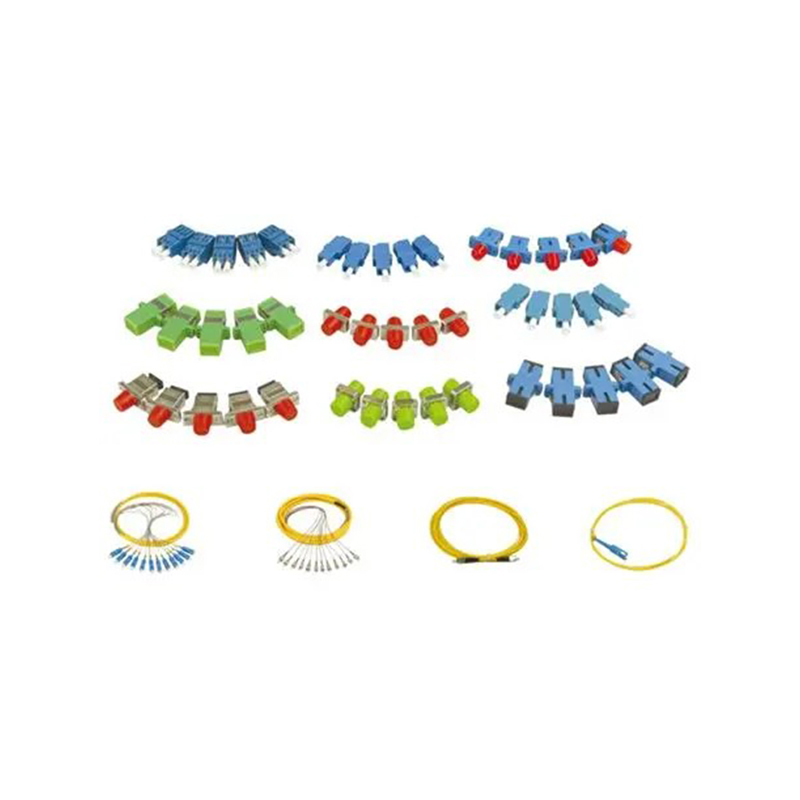
Fiber Solution-Patch Cords, Pigtail, Adaptor
5. Optical Performance Advantages
The product is designed to provide low insertion loss and high return loss, two fundamental indicators of optical interconnection quality.
5.1 Low Insertion Loss
Insertion loss is the amount of optical power lost when a component is inserted into a transmission path. Every connector, adaptor, splice, and passive device contributes some degree of loss. While a single connection may contribute only a small amount, the total loss of a network can become significant when many connection points are combined.
Low insertion loss helps preserve the available power budget. This is important in access networks, long-distance links, high-density distribution systems, and applications where optical transmitters and receivers have limited operating margins. Lower connection loss can also provide greater flexibility when the network is expanded or additional passive components are introduced.
High-precision ferrules, accurate fiber positioning, and controlled end-face geometry all contribute to lower insertion loss. The objective is to create a connection in which the optical cores are aligned as accurately as possible and the physical interface remains stable after mating.
5.2 High Return Loss
Return loss describes the amount of optical power reflected toward the source rather than continuing through the transmission path. A higher return loss value indicates lower reflected power. Excessive reflection can affect some optical transmitters, receivers, and sensitive transmission systems, particularly where signal quality and link stability are important.
High return loss depends on the quality of the connector interface, including end-face contact, polish condition, surface cleanliness, geometry, and alignment. A carefully polished end face can reduce unwanted reflection and help maintain a more predictable optical path.
For modern Ethernet, transport, access, and 5G-related networks, stable optical parameters are valuable because network equipment may operate at increasingly higher data rates and tighter performance margins. Consistent connector quality supports the overall design objective of maintaining signal integrity across the complete link.
5.3 Interchangeability
Interchangeability is another important advantage. A standardized connector should mate correctly with a compatible connector or adaptor from the same recognized interface family. This allows network operators to install, replace, and rearrange components without redesigning the entire distribution system.
Interchangeability depends on dimensional accuracy, connector standardization, ferrule quality, housing design, and manufacturing consistency. When these elements are controlled, replacement work becomes more predictable. Technicians can keep suitable spare components available and reduce the time required to restore a connection.
For project contractors and system integrators, interchangeable components can also simplify procurement and installation planning. Standardized interfaces make it easier to coordinate patch panels, optical modules, distribution frames, and cable assemblies from a broader equipment ecosystem.
6. Mechanical and Environmental Reliability
Optical performance alone is not sufficient for a field-deployed fiber component. The product must also withstand the mechanical and environmental conditions encountered during installation and operation.
Patch cords may be routed, repositioned, and handled many times. Pigtails may be bent during splice organization and placed inside trays or fiber management units. Adaptors may be exposed to repeated connector insertion and removal. These activities place demands on the connector housing, cable structure, ferrule retention, and strain-relief design.
The product is designed to provide stable environmental performance and mechanical properties that meet industrial standards. This means the components are intended to maintain their basic functional characteristics within the conditions specified for their application. Depending on the installation environment, relevant considerations may include temperature variation, humidity, vibration, mechanical shock, cable bending, connector retention, and repeated mating.
6.1 Mechanical Stability
Mechanical stability helps ensure that the fiber remains correctly positioned inside the connector. It also helps prevent movement that could change the optical alignment after installation. A well-constructed assembly should protect the transition between the cable and connector, where bending and pulling forces can otherwise concentrate.
In a cabinet or distribution frame, organized routing reduces mechanical stress. However, the product itself must still be capable of handling normal installation forces. Reliable strain relief and secure connector construction help reduce the likelihood of damage caused by accidental pulling or improper handling.
6.2 Environmental Resistance
Communication equipment can be installed in air-conditioned equipment rooms, industrial buildings, railway facilities, outdoor cabinets, and other locations with different environmental conditions. Temperature and humidity changes can affect materials, connector interfaces, and cable jackets. Dust and contamination can also degrade optical contact if components are not properly protected and maintained.
Stable environmental performance supports predictable operation over time. It also helps reduce the risk that a connection will change significantly as the installation environment changes. For network owners, this can contribute to lower maintenance requirements and greater confidence in long-term infrastructure performance.
6.3 Industrial Standards
Meeting applicable industrial standards provides a common basis for evaluating optical and mechanical characteristics. Standards may address connector dimensions, optical performance, environmental testing, mechanical testing, and compatibility. Compliance with relevant requirements helps system designers compare products and select components suitable for their network architecture.
Standards alone do not replace manufacturing quality, but they provide an important framework. A supplier with established production procedures and practical communication equipment experience is better positioned to translate those requirements into reliable products for real installations.
7. Manufacturing Strengths and Process Control
The quality of a fiber interconnection product is determined by the entire manufacturing chain, not by a single material or process. It begins with component selection and continues through ferrule preparation, fiber insertion, adhesive curing, connector assembly, end-face grinding, inspection, cleaning, testing, packaging, and delivery.
7.1 Material and Component Selection
High-precision ferrules are selected to support accurate fiber alignment. Connector bodies, adaptors, boots, cable jackets, and other components must be compatible with the intended application. Material selection affects dimensional stability, mechanical strength, environmental performance, and service life.
Consistent incoming materials help reduce variation in later manufacturing stages. A disciplined supplier management process can help ensure that ferrules and other critical components meet defined specifications before they enter production.
7.2 Fiber Preparation and Assembly
Fiber preparation must be carried out carefully to prevent contamination, damage, or excessive stress. The fiber must be positioned correctly inside the ferrule, and the assembly must be secured so that it remains stable during curing and polishing.
Assembly accuracy is particularly important because the polishing process cannot correct every underlying alignment problem. A connector that begins with incorrect fiber positioning may not achieve the desired optical performance even if its end face appears visually acceptable. For this reason, fiber insertion, adhesive application, curing, and ferrule handling require controlled procedures.
7.3 Controlled Curing
Adhesive curing stabilizes the fiber and ferrule assembly. Inadequate or inconsistent curing can lead to movement, stress, or changes in alignment over time. A controlled curing process considers adhesive quantity, curing time, temperature, fixture condition, and handling procedures.
Stable curing supports the mechanical reliability of the connector and helps ensure that polishing produces a repeatable end face. It also contributes to the component’s ability to withstand normal environmental and mechanical conditions.
7.4 Precision Grinding and Polishing
Grinding and polishing are central to the product’s optical performance. The process is designed to control apex offset, end-face geometry, curvature radius, and surface quality. Different stages may be used to remove material, refine the surface, and achieve the required finish.
Modern grinding machinery can improve process repeatability by controlling fixture pressure, polishing movement, processing time, and consumable conditions. Equipment capability must be supported by correct calibration and regular maintenance. Operators must also monitor process results and respond to variation before it affects a large production batch.
7.5 Inspection and Testing
Inspection may include visual examination of the end face, dimensional checks, connector interface verification, and optical performance testing. Testing helps identify excessive insertion loss, insufficient return loss, alignment defects, physical damage, or assembly inconsistency.
Inspection is most effective when it is integrated throughout the process rather than limited to the final stage. Monitoring incoming materials, assembly quality, polishing results, and finished-product performance creates multiple opportunities to prevent defects and improve consistency.
7.6 Cleaning and Packaging
Even a precisely manufactured connector can perform poorly if its end face becomes contaminated. Cleaning and protective packaging are therefore important final steps. Dust caps and suitable packaging help protect the interface during transportation and storage.
Clear product identification and organized packaging also support installation efficiency. Contractors can more easily match components to project specifications, connector types, lengths, and quantities when products are consistently labeled and protected.
8. Advantages Over Less Specialized Alternatives
Fiber interconnection products from different suppliers may appear similar, but their performance can vary because of differences in material quality, tolerance control, polishing capability, inspection systems, and production experience. The advantages of this product are most apparent when it is compared with components manufactured using less precise or less controlled methods.
8.1 More Consistent Optical Performance
Products made with high-precision ceramic ferrules and controlled polishing processes are more likely to deliver consistent insertion loss and return loss across multiple units. This consistency is valuable in large projects, where a small variation in each connector can accumulate into a significant difference in total link performance.
Less specialized alternatives may rely on broader mechanical tolerances or less controlled end-face preparation. Such products may function in simple links but create additional uncertainty in high-density, high-speed, or long-term infrastructure applications.
8.2 Better Compatibility with Structured Distribution Systems
Patch cords, pigtails, and adaptors designed for optical distribution equipment can be integrated more easily into ODFs, OMDFs, OCCs, and related cabinets. Their standardized interfaces and application-focused construction support orderly deployment.
Generic components may not always provide the same level of fit, cable routing suitability, connector retention, or accessory compatibility. In a densely populated distribution frame, small differences in housing dimensions or cable flexibility can complicate installation and maintenance.
8.3 Improved Maintenance Efficiency
Reliable connector interfaces reduce the likelihood that routine changes will create new optical problems. Technicians can disconnect and reconnect patch cords more confidently when the connectors are manufactured for stable mating and interchangeability.
The modular relationship between pigtails, adaptors, and patch cords also helps separate permanent cable work from routine service operations. This can reduce the need to disturb splices and improve the efficiency of troubleshooting and network reconfiguration.
8.4 Stronger Support for Demanding Infrastructure
Telecom, railway, urban rail transit, and 5G-related facilities often require more than basic connectivity. They require dependable components that can support complex cable management, repeated maintenance, high port density, and extended service periods.
A supplier with experience in communication cabinets, electronic equipment, and passive optical components can provide products that are more closely aligned with these system-level requirements. This broader perspective is a practical advantage over suppliers focused only on isolated, low-complexity connector sales.
8.5 Greater Project Customization Potential
Different projects may require specific connector configurations, fiber types, lengths, jacket materials, adaptor arrangements, packaging methods, or distribution cabinet interfaces. A manufacturer with its own product development and production capabilities can respond more effectively to such requirements.
Wanma Technology develops, manufactures, and markets its own branded products while also providing integrated solutions for customized products. This capability can help project owners and system integrators coordinate product design, manufacturing, delivery, and technical communication through a more unified supply relationship.
9. Integration with Ethernet and 5G FTTH Modernization
Modern communication infrastructure increasingly combines fiber backbones, Ethernet access networks, optical distribution systems, and high-capacity service platforms. Fiber patch cords, pigtails, and adaptors provide the physical connectivity required to link these systems together.
In Ethernet optical networks, patch cords may connect optical transceivers, switches, distribution panels, and transport equipment. Low insertion loss helps preserve the link budget, while accurate connector alignment supports stable operation. In central equipment rooms, organized fiber connections also improve the ability to expand switch capacity and modify service paths.
5G network modernization places additional demands on transport and access infrastructure. Radio access sites, aggregation points, core facilities, and edge locations may all require fiber connections. Although the product is passive, its performance contributes to the reliability of the active equipment connected through the optical distribution system.
FTTH modernization projects also depend on scalable fiber distribution. As more homes, businesses, and public facilities receive high-bandwidth services, distribution points must support a growing number of optical connections. Pigtails and adaptors can provide structured termination, while patch cords allow flexible assignment of fibers and equipment ports.
The product does not replace active network equipment, optical modules, or network management systems. Instead, it provides the precise physical interface that allows those systems to work together. A reliable passive connection is therefore an essential part of the overall network modernization process.
10. Installation and Maintenance Considerations
Correct installation is necessary to obtain the intended performance of precision optical components. Technicians should verify connector type, fiber type, polarity, cable length, adaptor compatibility, and distribution frame layout before beginning installation.
10.1 Protecting the End Face
Connector end faces should remain covered until they are ready for use. Dust caps should be replaced whenever a connector is disconnected. Before mating, the end face should be inspected and cleaned using suitable fiber optic cleaning procedures.
Contamination is one of the most common causes of increased insertion loss and unstable optical performance. Even a small particle can create an air gap or scratch the polished surface. Proper handling protects the investment in high-precision manufacturing.
10.2 Managing Bend Radius
Patch cords and pigtails should be routed according to the applicable minimum bend radius. Excessive bending can increase attenuation and place stress on the fiber or connector transition. Cable management rings, guides, trays, and tie systems should be used carefully so that they secure the cable without crushing or sharply bending it.
Neat routing is particularly important in high-density cabinets. A well-organized cable path makes it easier to identify ports, perform testing, and replace components without disturbing adjacent connections.
10.3 Avoiding Excessive Pulling Force
Connectors should be inserted and removed by their designated housing or boot rather than by pulling on the fiber cable. Excessive force can damage the strain-relief area or change the internal alignment. When patch cords are routed across a rack, sufficient slack should be provided for maintenance without allowing loose loops to obstruct other equipment.
10.4 Verifying Optical Performance
After installation, technicians may test the link using appropriate optical measurement equipment. Testing can help confirm insertion loss, return loss, continuity, polarity, and overall link performance. Baseline test records are useful for future maintenance because they provide a reference against which later changes can be compared.
10.5 Planning for Expansion
Fiber distribution systems should be planned with future growth in mind. Spare adaptors, reserved rack space, adequate patch cord lengths, and clearly documented port assignments can simplify later expansion. Products with standardized interfaces and consistent dimensions make it easier to add new connections without redesigning the existing system.

11. Why Choose an Experienced Communication Equipment Manufacturer
The supplier relationship is an important part of optical infrastructure procurement. A product may meet a basic specification, but project success also depends on manufacturing continuity, delivery coordination, customization capability, technical communication, and after-sales support.
Wanma Technology Co., Ltd. was established in 1997 and has developed experience in communication cabinets, communication electronic equipment, and passive optical components. Its products are used in Ethernet networks, optical communication networks, central equipment rooms, national high-speed railways, and urban rail transit systems.
This application range demonstrates familiarity with both standard communication environments and infrastructure projects with demanding operational requirements. The company’s product portfolio allows it to understand how fiber components are installed inside cabinets, frames, distribution systems, and other communication equipment.
Wanma Technology develops, manufactures, and markets its own branded products. Internal control over product development and manufacturing can support more direct communication between engineering, production, quality, and sales teams. It can also make it easier to coordinate product changes or customized requirements for project customers.
The company also provides integrated solutions for customized products. Customization may involve product configuration, interface selection, cable length, packaging, equipment integration, or other project-specific details. A manufacturer able to manage these requirements can help reduce coordination complexity for contractors and system integrators.
Its sales network covers more than 20 countries and regions, including the United States, Australia, the United Kingdom, Italy, South Africa, and Ghana. International experience requires attention to communication, documentation, delivery arrangements, product consistency, and customer service across different markets.
Wanma Technology emphasizes reliable product quality, timely delivery, and long-term strategic partnerships with industry leaders. These priorities are relevant to optical network projects because passive components are often required in significant quantities and must arrive according to an installation schedule. Delayed or inconsistent components can affect cabinet assembly, commissioning, and network activation.
12. Project Procurement Benefits
For network owners and contractors, purchasing patch cords, pigtails, and adaptors from an experienced manufacturer can provide several practical benefits. First, a stable source can help maintain consistent specifications across different phases of a project. This is particularly important when construction occurs in multiple locations or over an extended period.
Second, a manufacturer with a broader communication equipment portfolio may be able to coordinate fiber components with cabinets, distribution frames, and electronic equipment. This can reduce compatibility risks and simplify technical discussions during the design stage.
Third, an established quality process can support more predictable acceptance testing. When the supplier maintains consistent production procedures, project teams can develop repeatable inspection and commissioning workflows.
Fourth, direct access to a manufacturer can be helpful when a project requires non-standard quantities, special cable lengths, customized labels, or integrated product solutions. Instead of adapting the project to a fixed catalogue item, the customer may be able to work with the supplier to define a suitable configuration.
Finally, long-term supplier cooperation can support network expansion and maintenance. As the installed base grows, the customer may need additional patch cords, replacement adaptors, new pigtails, or components for upgraded equipment. A reliable supplier relationship helps preserve continuity between the original installation and later changes.
13. Quality, Reliability, and Long-Term Network Value
Optical distribution components are often expected to remain in service for many years. Their value should therefore be measured not only by initial purchase price, but also by installation efficiency, optical stability, maintenance requirements, compatibility, and the risk of service disruption.
A connector with poor alignment may create a problem that is difficult to diagnose because the network can remain partially operational while performance margins gradually decline. A connector with an inconsistent end face may produce intermittent results after repeated handling. A mechanically weak cable transition may fail after routine movement or accidental stress.
High-precision ferrules and controlled polishing help address these risks at the source. Stable material selection and mechanical construction support continued physical alignment. Interchangeable interfaces make replacement more straightforward. Industrial-standard performance provides a basis for selecting components that fit the demands of the intended application.
The result is a product designed to contribute long-term value to the complete optical network. It supports not only the first connection, but also future testing, reconfiguration, expansion, and repair.
14. Recommended Selection Criteria
When selecting patch cords, pigtails, and adaptors, buyers should evaluate the complete product specification rather than considering only connector type or purchase price.
14.1 Application Compatibility
Confirm that the product is suitable for the intended OMDF, ODF, OCC, cabinet, splice tray, optical distribution box, or other equipment. The connector housing, adaptor structure, and cable dimensions should fit the available space and management system.
14.2 Optical Requirements
Review insertion loss, return loss, fiber mode, wavelength range, and any project-specific optical requirements. In high-density and high-speed systems, consistent performance across the complete batch is particularly important.
14.3 Mechanical Requirements
Consider connector retention, cable flexibility, strain relief, repeated mating, bend performance, and resistance to expected mechanical conditions. Railway and industrial installations may require additional attention to vibration and environmental variation.
14.4 Environmental Requirements
Evaluate temperature, humidity, dust, installation location, and expected service conditions. Components used in controlled equipment rooms may face different requirements from those installed in transport facilities or less controlled cabinets.
14.5 Manufacturing and Quality Capability
Ask whether the supplier uses high-precision ferrules, controlled grinding and polishing equipment, inspection procedures, and traceable production methods. These factors provide insight into the supplier’s ability to deliver consistent products at project scale.
14.6 Delivery and Customization
Confirm production capacity, delivery schedules, packaging, labeling, documentation, and the supplier’s ability to support customized configurations. These details can significantly influence project execution.
| Selection Area | Questions for Buyers | Expected Benefit |
|---|---|---|
| Optical performance | Are insertion loss and return loss suitable for the link budget? | More stable transmission and greater design margin |
| Ferrule precision | Are concentricity and bore dimensions controlled? | Improved fiber-core alignment and consistency |
| End-face quality | Are apex offset, curvature radius, and surface condition controlled? | Reliable physical contact and lower reflection |
| Mechanical design | Can the assembly withstand handling, routing, and repeated mating? | Lower risk of physical damage during service |
| System compatibility | Will the components fit the selected ODF, OMDF, OCC, or cabinet? | Faster installation and easier maintenance |
| Supplier capability | Can the manufacturer support quality, delivery, and customization? | Reduced procurement and project coordination risk |
15. Q&A
Q1: What are patch cords, pigtails, and adaptors used for?
They are optical interconnection components used to terminate, connect, distribute, and manage fibers. Patch cords connect optical interfaces, pigtails provide connectorized ends for splicing to optical cables, and adaptors mechanically align two compatible optical connectors.
Q2: Where are these products commonly installed?
They are mainly used in Optical Main Distribution Frames, Optical Distribution Frames, Optical Cross-Connects, optical cabinets, splice trays, central equipment rooms, Ethernet networks, optical communication systems, railway communication facilities, urban rail transit networks, and 5G or FTTH modernization infrastructure.
Q3: Why is the ceramic ferrule important?
The ceramic ferrule holds the fiber in a precise position and supports accurate alignment with the mating connector. A ferrule with low concentricity error and a controlled bore can help reduce alignment problems and protect insertion and return loss performance.
Q4: What is insertion loss?
Insertion loss is the optical power lost when a component is introduced into a transmission path. Lower insertion loss helps preserve the optical power budget and supports stable operation, especially when a network contains many connectors and passive components.
Q5: What is return loss?
Return loss indicates the amount of optical power reflected back toward the source. A higher return loss value generally means less reflected power. Good end-face polishing, alignment, cleanliness, and physical contact contribute to high return loss.
Q6: Why are apex offset and curvature radius controlled?
These end-face parameters influence how two connector surfaces contact and align. If they are outside the intended range, the connection may experience greater reflection, higher insertion loss, or inconsistent performance during repeated mating.
Q7: Can the components be used for railway and urban rail transit networks?
They are suitable for optical distribution applications in railway and urban rail transit communication systems when the selected configuration meets the project’s optical, mechanical, and environmental requirements. Wanma Technology has experience supplying communication products used in national high-speed railway and urban rail transit systems.
Q8: How should connectors be maintained?
Keep connector end faces protected with dust caps when they are not in use. Inspect and clean them before mating, avoid touching the polished surface, follow the required bend radius, and do not pull on the fiber cable when inserting or removing a connector.
Q9: Can customized products be supplied?
Customized solutions may be available according to project requirements. Possible considerations include connector configuration, cable length, fiber type, adaptor arrangement, labeling, packaging, and integration with communication equipment. Requirements should be confirmed with the manufacturer before production.
Q10: What distinguishes a precision-manufactured component from a basic alternative?
A precision-manufactured component uses controlled materials, accurate ferrules, disciplined assembly, advanced grinding and polishing, inspection, and standardized testing. These practices can improve consistency, interchangeability, mechanical reliability, and long-term network performance.
Q11: Why is supplier experience important for passive optical products?
Passive components must fit into real cabinets, frames, splice systems, and network maintenance procedures. A supplier experienced in communication equipment and optical infrastructure is more likely to understand these system-level requirements and provide suitable product and project support.
Q12: How can these products support future network expansion?
Standardized and interchangeable patch cords, pigtails, and adaptors allow new connections to be added and existing paths to be rearranged without replacing the entire distribution system. Consistent products also make it easier to maintain spare parts and extend installations across multiple sites.
16. Conclusion
Patch cords, pigtails, and adaptors are essential building blocks of organized and reliable optical communication infrastructure. Their small physical size does not reduce their importance. Accurate fiber alignment, controlled end-face geometry, low insertion loss, high return loss, mechanical stability, environmental reliability, and interchangeability all contribute to the performance of the complete network.
The product’s high-precision ceramic ferrules help maintain accurate fiber positioning, while advanced grinding technology and controlled machinery support the management of apex offset, end-face condition, curvature radius, and related parameters. These manufacturing strengths help distinguish the product from less specialized alternatives that may offer lower consistency or limited compatibility with demanding distribution systems.
Its applications in OMDF, ODF, OCC, central equipment rooms, Ethernet networks, optical communication networks, railway communication facilities, urban rail transit systems, and 5G and FTTH modernization projects demonstrate the broad role of precision passive connectivity. Whether used in a new deployment, a network upgrade, or a long-term maintenance program, the components provide a practical interface between fixed optical cable infrastructure and active communication equipment.
Wanma Technology Co., Ltd. adds value through its long-standing experience in communication cabinets, communication electronic equipment, and passive optical components. Since its establishment in 1997, the company has developed, manufactured, and supplied products for communication applications in China and international markets. Its manufacturing capabilities, customized solution support, international sales network, and focus on product quality and timely delivery make it a suitable partner for structured optical network projects.
For network owners, contractors, and system integrators, selecting a precision-focused manufacturer can reduce installation uncertainty, simplify maintenance, improve compatibility, and support dependable network growth. In modern Ethernet, railway transit, 5G, and FTTH infrastructure, reliable optical interconnection is not an accessory. It is a fundamental requirement for building networks that perform consistently today and remain adaptable for the future.
References
1. International Electrotechnical Commission, relevant standards for fiber optic interconnecting devices and passive components.
2. International Organization for Standardization and International Electrotechnical Commission, generic cabling principles for information technology and optical fiber infrastructure.
3. Telecommunications industry guidance on fiber optic connector inspection, cleaning, installation, and maintenance.
4. Technical literature concerning optical insertion loss, return loss, fiber-core alignment, ferrule concentricity, and connector end-face geometry.
5. Engineering publications on optical distribution frames, optical cross-connect systems, structured fiber management, and high-density communication cabinets.
6. Railway and urban rail transit communication infrastructure guidance concerning optical backbone networks and equipment-room connectivity.
7. Manufacturer technical information regarding patch cords, pigtails, adaptors, passive optical components, communication cabinets, and customized communication equipment solutions.
Product: Fiber Solution-Patch Cords, Pigtail, Adaptor
PREV:How an Intelligent Medical Cart Improves ICU Nursing Efficiency, Safety, and Mobility
NEXT:Compact Fiber Optic Distribution Box for Reliable FTTH Network Deployment
NEXT:Compact Fiber Optic Distribution Box for Reliable FTTH Network Deployment
Interested in cooperation or have questions?
Related products
-
-
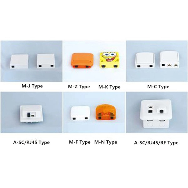
Application:It can be applied to FTTH, FTTO, FTTB applications and also has the functions of splicing, welding and installing connectors. Features:•Large variety; Full specification; Pleasing appearan...
See Details -
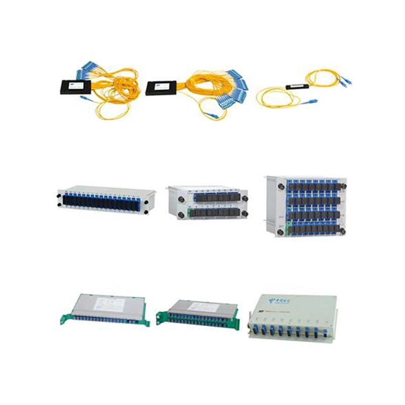
Application:It is used to split one optical signal to multiple output ports. The splitters can be divided into the micro type splitter, the box type splitter, the tray type splitter, and the frame typ...
See Details -
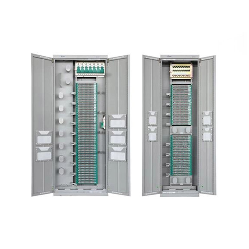
Application ScopeThe GPX129-09T fiber optic distribution frame is used to connect, distribute, and manage fiber optic cables and optical communication equipment. It is suitable for large-capacity fibe...
See Details
Ready to Get started ? Contact Us Now !

Product.
Contact Details.
-
 +86 13958188250
-
 +86 13958188250
-
 [email protected]
-
 AUDIT Email:[email protected]
- Wanma Industrial Park Taihu Yuan Town Lin'an District Hangzhou City China.
QR Code

Copyright © Wanma Technology Co., Ltd. All Rights Reserved.
Privacy
Custom Ethernet Optical Network Railway Transit Equipments Suppliers
