

 English
 Français
 Español
 Português
 عربى






WM-1001-F055 It offers a wide range of functions which is needed in your Ftth broadband project in a compact and smart design. Extremely compact/variable transfer unit Multifunctional base plate Vario...
See DetailsCompact Fiber Optic Distribution Box for Reliable FTTH Network Deployment
Content
- 1 1. The Role of a Fiber Optic Distribution Box in FTTH Networks
- 2 2. Product Overview
- 3 3. Compact Design for Space-Constrained Installations
- 4 4. Three-Part Housing and Improved Installation Workflow
- 5 5. Intelligent Cable Guidance and Cable Entry Flexibility
- 6 6. Splicing, Connectorization, and Splitter Integration
- 7 7. Environmental Protection and Access Control
- 8 8. Advantages Compared with Less Flexible Distribution Enclosures
- 9 9. Manufacturing and Product Development Strengths
- 10 10. Advanced Manufacturing Considerations for Optical Enclosures
- 11 11. Quality, Reliability, and Lifecycle Value
- 12 12. Applications Across Different Markets
- 13 13. Technical Specifications
- 14 14. Installation Recommendations
- 15 15. Procurement and Project Planning
- 16 16. Why Supplier Capability Matters
- 17 17. Maintenance and Future Expansion
- 18 18. Frequently Asked Questions
- 18.1 What is the WM-1001-F055 used for?
- 18.2 How large is the distribution box?
- 18.3 How much does it weigh?
- 18.4 What connector types can be used?
- 18.5 Can the box accommodate a PLC splitter?
- 18.6 What microduct sizes are supported?
- 18.7 Does the box support different splice methods?
- 18.8 Is the enclosure suitable for outdoor use?
- 18.9 Can unauthorized users open the box?
- 18.10 What makes the product different from a basic splice box?
- 18.11 What should be confirmed before purchase?
- 18.12 Can customized versions be requested?
- 19 19. Conclusion
- 20 References
- 21 Product: WM-1001-F055 Fiber Optic Distribution Box
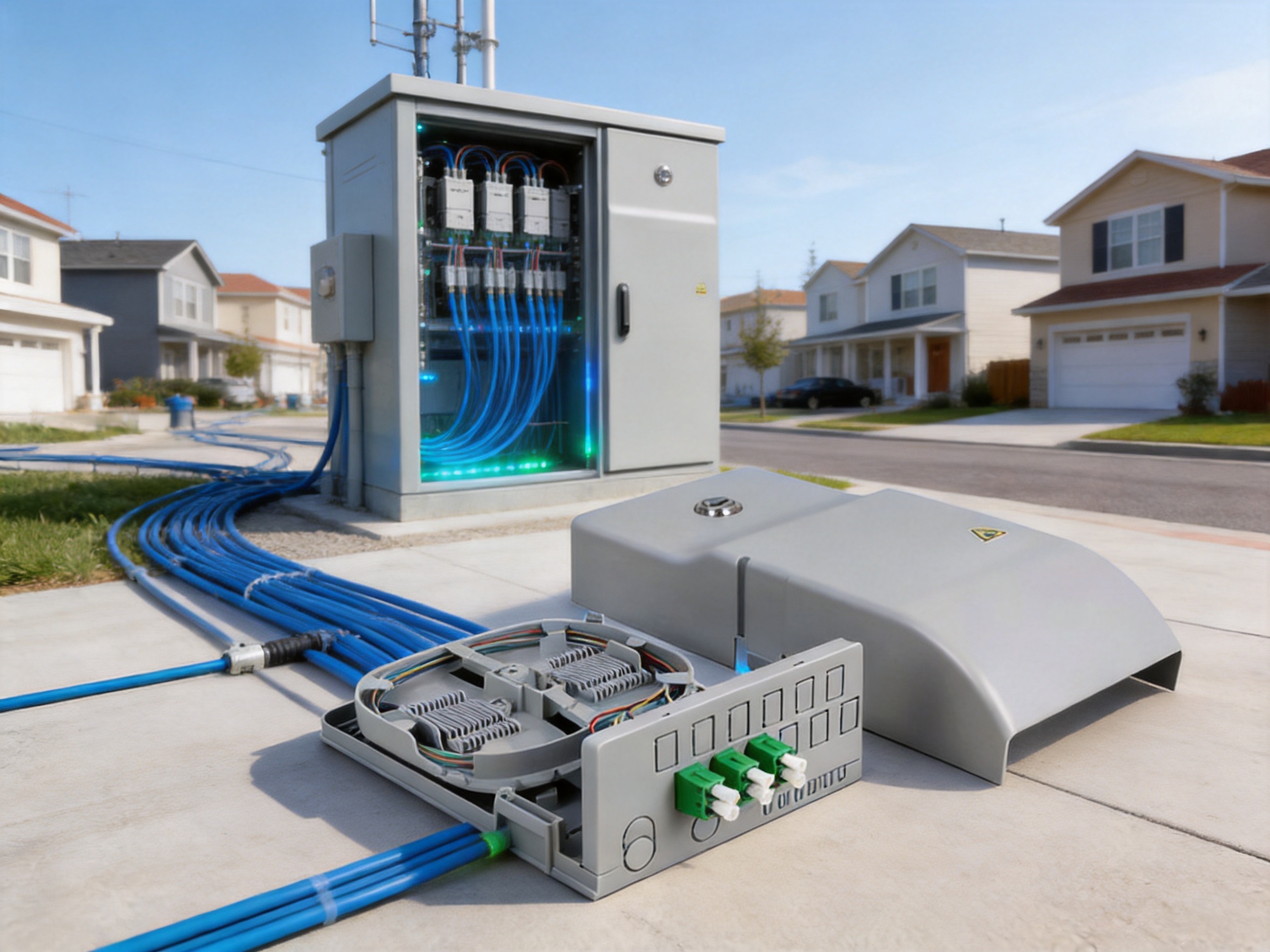
Modern broadband networks require more than high-capacity fiber cables and advanced optical equipment. They also need compact, organized, and dependable distribution points that protect fiber connections while making installation, maintenance, and future expansion easier. The WM-1001-F055 Fiber Optic Distribution Box is designed for this important role in fiber-to-the-home, broadband cable, utility, and other optical communication applications.
As a versatile fiber closure and distribution unit, the product combines cable management, splice protection, connector accommodation, splitter installation, and subscriber-side access control in a compact housing. Its three-part construction allows installers to work freely on the base plate before the remaining housing sections are fitted. This approach can improve installation efficiency and reduce unnecessary handling of delicate optical fibers.
The product is intended for FTTH and FTTX projects in which space is limited but network organization and service reliability remain essential. With dimensions of approximately 122 × 59 × 256 mm and a weight of about 335 g, the box is suitable for locations where a larger cabinet or wall-mounted distribution enclosure would be impractical. Its IP54 environmental rating provides resistance against dust, dirt, and sand, helping protect internal components in suitable indoor and semi-protected outdoor environments.
Beyond its physical design, the distribution box reflects the product development strengths of Wanma Technology Co., Ltd., a manufacturer with experience in communication cabinets, communication electronic equipment, passive optical components, Ethernet networks, optical communication systems, railway communication, and urban rail transit applications. The company’s ability to develop, manufacture, and market its own products supports a practical approach to product consistency, project customization, and long-term customer service.
1. The Role of a Fiber Optic Distribution Box in FTTH Networks
Fiber-to-the-home networks depend on a sequence of carefully managed connection points. Optical signals travel from a central office or equipment room through feeder cables, distribution cables, splitters, splice points, and drop cables before reaching subscribers. Each transition must be protected and organized to ensure that network performance is not compromised by excessive bending, contamination, poor splicing, or accidental disconnection.
A fiber optic distribution box provides a controlled location for these activities. It may receive incoming cables, guide and secure fibers, house passive optical splitters, protect splice points, and provide connector interfaces for outgoing fibers. The enclosure also gives technicians a practical location for commissioning, troubleshooting, and network expansion.
In an FTTH deployment, the distribution box may be installed in a building, telecommunications room, utility area, corridor, service cabinet, or other designated location. The exact installation environment depends on project design and local requirements. Regardless of location, the main objectives are generally the same: protect the optical components, maintain an orderly fiber path, provide sufficient capacity, and make future maintenance straightforward.
Poorly designed distribution points can create several operational problems. Fibers may be bent too sharply, splice trays may be difficult to remove, cable entries may not align with the project route, and connectors may be exposed to dust or accidental impact. Technicians may also spend excessive time opening and reorganizing the enclosure. These issues can increase installation costs and create avoidable service risks.
The WM-1001-F055 addresses these challenges through a compact three-part housing, an intelligent cable guide, a multifunctional base plate, multiple cable entry options, and a versatile splice cassette. These features are intended to provide a practical balance between capacity and physical size.
2. Product Overview
The WM-1001-F055 is a fiber optic distribution box developed for FTTH broadband projects and related optical communication applications. It is described as a versatile, easy-to-use fiber closure for FTTX networks. Its design supports fiber routing, splicing, optical coupling, and splitter integration within one compact unit.
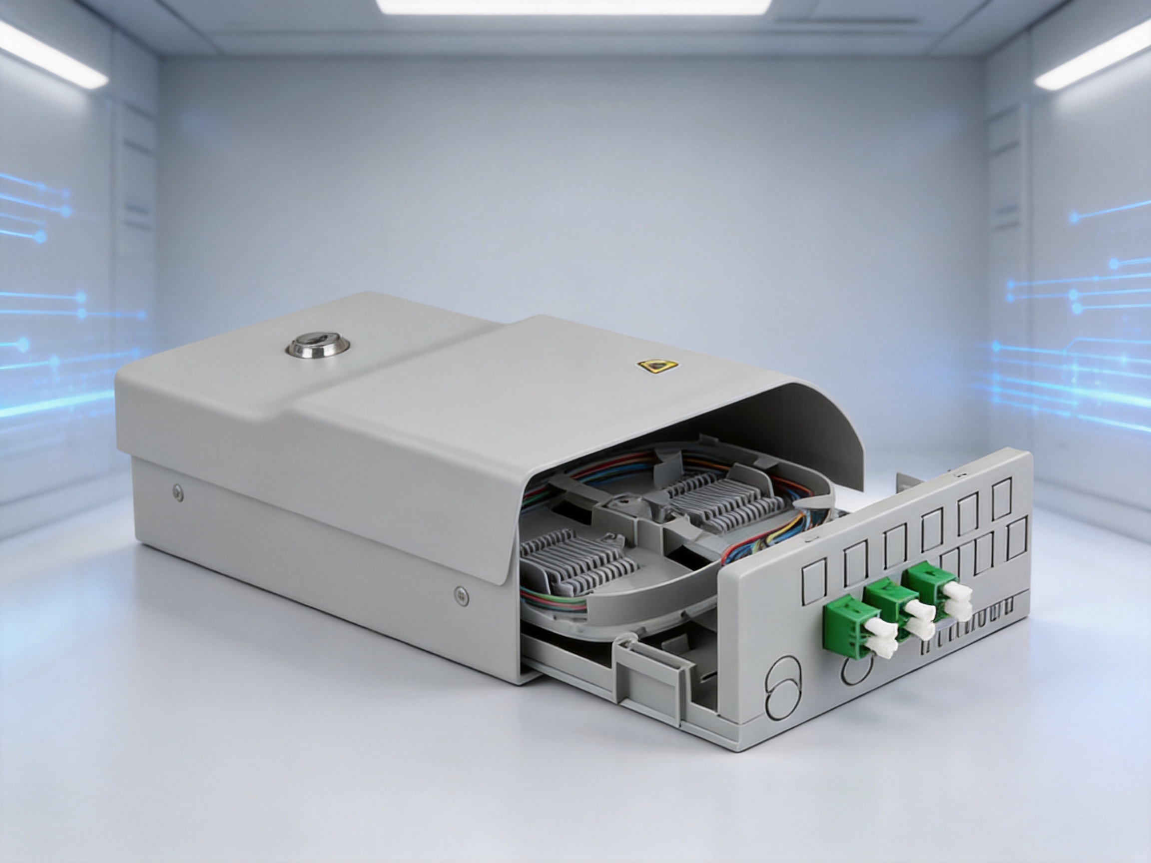
The enclosure has a long protective lid that helps prevent unauthorized subscriber access to internal connections. A built-in cylinder lock can be used to secure the lid, while a side sealing arrangement supports additional protection for the splice box. These features are valuable in shared buildings and public or semi-public installation environments where access control is important.
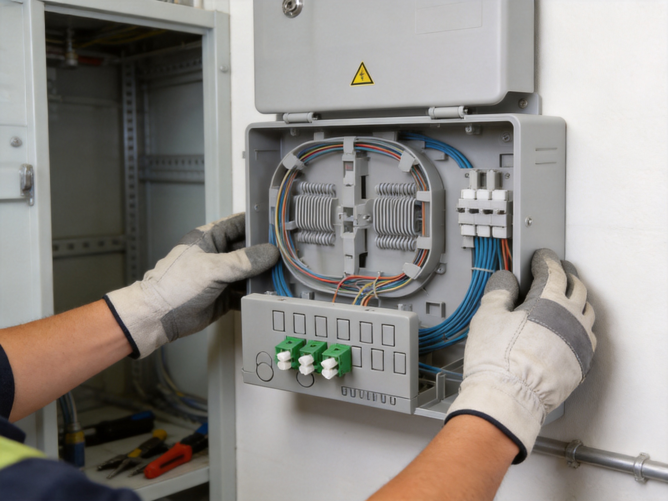
The distribution unit includes a multifunctional base plate. The base plate is installed at the desired location and allows the technician to perform much of the working procedure before closing the complete housing. This can make the installation process more convenient because the technician is not required to repeatedly work through a narrow or obstructed opening.
The base plate also provides space for a PLC splitter holder, cable entry arrangements, a splice receptacle, and through-splice applications. The design allows certain receptacles to be replaced with alternative splice or shrink fixtures, giving the installer flexibility to adapt the box to the selected splicing method and project requirements.
The upper or secondary attachment contains a splice cassette capable of accommodating up to 12 couplings and providing space for up to 24 fibers. Its twelve knockouts can be configured with connector combinations such as LC duplex, SC simplex, or E-2000® couplers, subject to the actual project configuration and compatible accessories.
Two receptacles in the splice cassette are fitted with crimp splice holders for twelve fibers each. These holders may be replaced with standard splice or shrink fixtures where the installation specification requires a different arrangement. This modular approach can reduce the need for a completely different enclosure when project conditions vary.
3. Compact Design for Space-Constrained Installations
One of the strongest advantages of the product is its compact size. Measuring approximately 122 × 59 × 256 mm, the enclosure occupies considerably less wall and cabinet space than many larger fiber distribution cabinets. Its slim profile can be especially useful in building corridors, telecommunications closets, vertical service areas, and compact utility spaces.
Space efficiency is increasingly important in modern network deployment. New fiber installations are often added to existing buildings where cable routes, equipment rooms, and wall surfaces are already crowded. A smaller distribution box can simplify site planning and reduce conflicts with electrical systems, ventilation equipment, building structures, or other communication devices.
A compact enclosure can also reduce the visual and physical impact of an FTTH installation. In multi-dwelling units, commercial buildings, and public infrastructure, equipment must often be installed without obstructing passageways or creating an untidy appearance. A well-organized compact unit supports a cleaner installation while preserving access for authorized technicians.
However, compactness is only beneficial when internal organization remains practical. An enclosure that is small but difficult to access may increase maintenance time. The WM-1001-F055 combines its compact external dimensions with a removable or separately installed base plate, structured cable routing, and a versatile cassette. These internal design features help make the available space more usable rather than simply reducing the enclosure size.
The product weighs approximately 335 g. Its low weight can simplify transportation, handling, and wall installation. Lightweight equipment may also reduce the mechanical load on mounting surfaces, although the installer should always select mounting hardware appropriate for the wall material and the complete installed configuration.
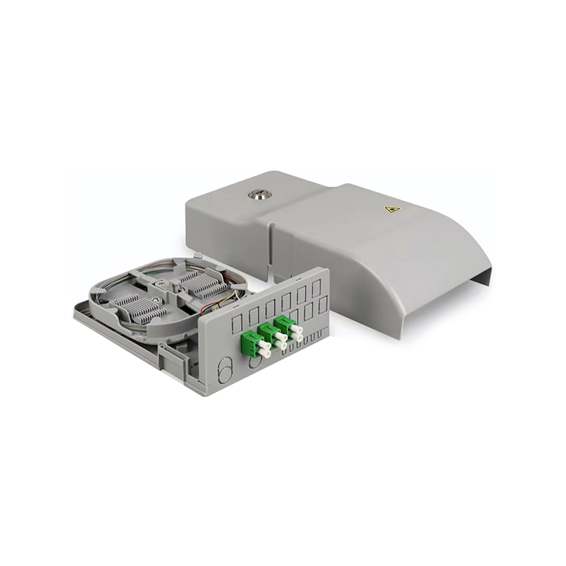
WM-1001-F055 Fiber Optic Distribution Box
4. Three-Part Housing and Improved Installation Workflow
The three-part housing is central to the product’s installation concept. The base plate is mounted first at the selected location. Once the base plate is secure, the installer can route cables, prepare splice components, position the splitter holder, and organize fiber paths with greater freedom.
This arrangement is useful because fiber optic work requires careful handling. Technicians need adequate space to strip cables, prepare fibers, perform splicing, inspect connections, and secure slack. If these operations must be completed inside a fully assembled enclosure, the work area may become crowded and the risk of fiber disturbance may increase.
By allowing the base plate to be attached first, the product supports a staged installation process. The installer can establish the physical foundation, prepare the internal arrangement, and then add the remaining housing sections. This can make the workflow more predictable, particularly in projects involving multiple cable types or several connection functions.
The three-part structure may also help during maintenance. Authorized personnel can access the appropriate section of the enclosure without unnecessarily disturbing every internal component. The exact maintenance procedure depends on the project configuration, but modular access generally supports better service organization than a single undifferentiated cavity.
Another benefit is reduced installation pressure in difficult locations. When a distribution box is installed in a narrow cabinet or near a ceiling, technicians may have limited hand movement. A base plate that can be prepared independently helps transfer some of the work to a more convenient stage of the installation.
The housing design also supports project standardization. Installers can use a consistent base plate and enclosure structure while adapting connector, splice, and cable entry components according to the network design. Standardized procedures can improve training, simplify inventory management, and reduce variation among installation teams.
5. Intelligent Cable Guidance and Cable Entry Flexibility
Fiber cables must be routed carefully to preserve signal quality and mechanical reliability. Excessive bending, uncontrolled movement, compression, and poorly secured cable jackets can all create problems. The WM-1001-F055 uses an intelligent cable guide to help installers lay down and fix cables in an orderly manner.
Controlled cable routing supports several objectives. First, it helps maintain appropriate bend paths. Second, it reduces the possibility of fibers becoming trapped beneath covers or splice components. Third, it makes the internal arrangement easier to understand when a technician returns for testing or repair. Finally, organized routing improves the visual quality of the installation and supports more consistent workmanship.
The base plate provides various cable entry options. Different FTTH projects may use different cable constructions, routes, and entry directions. A distribution box that only supports one entry method can force installers to create awkward bends or perform time-consuming modifications. Multiple entry options provide greater flexibility when the box must accommodate feeder, distribution, drop, or microduct pathways.
Two cut-outs on the base plate allow the insertion of 7 mm or 12 mm microducts. This feature is relevant to networks using microduct-based deployment methods. Microducts can help organize smaller fiber pathways and may support staged network construction, cable replacement, or capacity expansion. The available cut-outs enable the enclosure to connect with more than one commonly used microduct size.
Flexible entry arrangements can also be valuable in retrofit work. Existing buildings often do not provide ideal cable routes. The installer may need to approach the distribution point from above, below, or from the side. A box with adaptable entry provisions can reduce the amount of field modification required and help maintain a professional result.
Although the enclosure offers multiple entry options, the installer remains responsible for selecting suitable glands, seals, clamps, and routing methods for the specific application. Environmental performance depends on correct installation, complete closure, and the use of compatible components.
6. Splicing, Connectorization, and Splitter Integration
The WM-1001-F055 is not limited to one connection method. Its internal arrangement supports splicing, connectorized distribution, and PLC splitter installation. This multifunctional capability allows the product to serve different points in an FTTH network without requiring a separate enclosure design for every application.
The base plate includes a PLC splitter holder. Passive optical splitters are widely used in passive optical networks to distribute one optical signal among several subscribers or service endpoints. Integrating a splitter holder into the enclosure helps keep the splitter secure and supports a cleaner internal layout.
The product also provides space for a splice receptacle. This receptacle can be replaced by another splice or shrink receptacle where required. Such adaptability is useful because network operators and contractors may use different splicing technologies, protection sleeves, and installation procedures.
The lower area of the base plate and the crimp holder can be used for a through splice. Through splicing is relevant when fibers must pass through the distribution point while selected fibers are branched, connected, or terminated locally. Having space for this arrangement can help the enclosure support more complex network architectures.
The splice cassette can accommodate up to 12 couplings and provide space for up to 24 fibers. Its twelve knockouts may accept up to 12 LC duplex couplers, 12 SC simplex couplers, or 12 E-2000® couplers. The final capacity depends on the selected connector type, adapter layout, fiber management arrangement, and project specifications.
Connector flexibility is important because different network operators and regions may standardize on different connector interfaces. LC duplex connectors are often selected where high density is required. SC simplex connectors may be preferred for familiar handling and straightforward single-fiber connections. E-2000® couplers may be specified in networks requiring their particular mechanical and optical characteristics.
Supporting several connector options can reduce product-selection complexity. Instead of sourcing a different housing for every connector family, project planners can configure the same basic distribution platform to meet different interface requirements. This can help simplify procurement and improve consistency across network deployments.
The two receptacles in the splice cassette are occupied by two crimp splice holders for twelve fibers each. These holders may be replaced by standard splice or shrink fixtures. The possibility of replacing the holders allows the unit to support different field practices and gives installers greater freedom when selecting the preferred splice protection method.
7. Environmental Protection and Access Control
The WM-1001-F055 carries an IP54 rating. According to the supplied specifications, this rating indicates resistance to dust, dirt, and sand. The enclosure is therefore designed to provide a level of protection against environmental particles when properly assembled and installed.
IP54 protection can be valuable in telecommunications spaces, utility locations, broadband cable facilities, and other areas where airborne dust or dirt may be present. Keeping contaminants away from splices and connector interfaces helps reduce the possibility of contamination-related service problems.
The rating should not be interpreted as universal protection against every environmental condition. An IP54 enclosure is not automatically suitable for immersion, high-pressure water jets, or severe unprotected outdoor exposure. Project designers and installers should evaluate temperature, humidity, ultraviolet exposure, chemical conditions, vibration, and mounting location before approving the installation environment.
The specified ambient temperature range is approximately -25°C to 70°C. This broad operating range supports use in a variety of climate-controlled and non-climate-controlled network locations. Actual field performance depends on installation conditions, internal heat sources, solar exposure, and the behavior of all installed accessories.
The long lid provides an additional physical barrier that helps prevent subscriber access to internal components. In many FTTH installations, the subscriber should be able to use the service without being able to handle splice trays, splitter connections, or distribution fibers. Restricting access helps reduce the risk of accidental disconnection or damage.
A built-in cylinder lock can secure the lid. This is a practical feature for multi-user buildings, shared communication rooms, and public infrastructure. Access control also supports maintenance management because only authorized personnel should open the distribution section.
A sealing device on the side of the splice box provides another layer of protection. Correct sealing is important for preserving environmental performance and discouraging unauthorized opening. As with the IP rating, the final protection level depends on proper installation, compatible sealing methods, and the condition of the enclosure over time.
8. Advantages Compared with Less Flexible Distribution Enclosures
Many competing distribution boxes are designed around a single primary function, such as splice protection or connector termination. That approach can be suitable for simple installations, but it may require multiple product types when network designs vary. The WM-1001-F055 offers a broader combination of functions in one compact platform.
Its first advantage is multifunctionality. The same unit can accommodate a PLC splitter holder, splice receptacle, through-splice arrangement, splice cassette, and several connector formats. This reduces the need to use separate enclosures for closely related tasks.
Its second advantage is installation accessibility. The three-part housing allows the base plate to be mounted and worked on before final assembly. Some conventional compact boxes require technicians to complete nearly all work through a small front opening. The staged design of this product can make cable preparation and fiber organization more convenient.
Its third advantage is cable entry flexibility. Support for different entry arrangements and 7 mm or 12 mm microduct cut-outs can help the box adapt to different project layouts. A more rigid enclosure may require additional adapters, field drilling, or nonstandard cable routing.
Its fourth advantage is connector adaptability. Support for LC duplex, SC simplex, and E-2000® coupler configurations allows the product to be aligned with different operator standards. This can be helpful for contractors serving several customers with different network specifications.
Its fifth advantage is service organization. An intelligent cable guide, replaceable splice fixtures, and structured cassette arrangement can make the internal configuration easier to inspect and understand. Improved organization helps reduce the time needed for fault identification and future modifications.
Its sixth advantage is compactness without eliminating useful functions. Larger cabinets may provide more capacity, but they can be excessive for small distribution points. The WM-1001-F055 is positioned for applications that need meaningful fiber management and protection within a relatively small enclosure.
Its seventh advantage is access control. The long lid and built-in cylinder lock help separate subscriber use from technician-level network access. Not every small distribution unit provides this degree of physical control.
These advantages do not mean that one enclosure is suitable for every deployment. Very large networks may require higher-capacity cabinets, active equipment shelters, or specialized outdoor closures. The product’s strength is its balance of compact size, modular internal functions, and flexible configuration for appropriate FTTH and FTTX applications.
9. Manufacturing and Product Development Strengths
The product is manufactured by Wanma Technology Co., Ltd., a company established in 1997. The company specializes in communication cabinets, communication electronic equipment, and passive optical components. Its product portfolio is used in Ethernet networks, optical communication networks, central equipment rooms, national high-speed railway systems, and urban rail transit systems.
This range of applications is relevant to the development of a fiber distribution enclosure. Optical network products must be designed with attention to cable routing, mechanical protection, installation procedures, environmental conditions, and long-term serviceability. Experience across communication and transportation infrastructure can contribute to a practical understanding of how passive optical products are deployed in demanding network environments.
The company develops, manufactures, and markets its own branded products. This integrated structure can provide several advantages. Product development teams can communicate directly with manufacturing teams, allowing design details to be evaluated for production feasibility. Manufacturing feedback can be used to refine component selection, assembly procedures, and quality-control requirements.
Vertical coordination can also support better control over product consistency. When a manufacturer is responsible for both engineering and production, it can establish repeatable procedures for enclosure assembly, component fitting, cable management parts, locking mechanisms, and packaging. Consistency is particularly important for distribution boxes because installation teams rely on predictable dimensions and component interfaces.
Wanma Technology also provides integrated solutions for customized products. FTTH projects often differ in connector type, splitter arrangement, cable route, mounting condition, and capacity requirement. A manufacturer able to support customization can work with customers on configurations that are closer to actual project needs rather than forcing every installation into a fixed standard.
Customization should be based on controlled engineering and documented specifications. The important strength is not simply the ability to change a product, but the ability to evaluate requested changes, confirm compatibility, maintain quality, and deliver a repeatable configuration. A manufacturer with product development and production capabilities is better positioned to manage this process.
The company emphasizes reliable product quality, timely delivery, and long-term strategic partnerships. These priorities are significant for network operators and contractors because a distribution box is often purchased as part of a larger deployment schedule. Delayed components can interrupt cable installation, testing, and subscriber connection activities.
A sales network covering more than 20 countries and regions, including the United States, Australia, the United Kingdom, Italy, South Africa, and Ghana, indicates experience serving international markets. Different markets may involve different technical expectations, connector preferences, documentation requirements, installation practices, and environmental conditions. International supply experience can help a manufacturer understand the importance of clear specifications and consistent customer communication.
10. Advanced Manufacturing Considerations for Optical Enclosures
Although specific factory machinery and process parameters are not provided, the product’s design highlights several manufacturing priorities that are important in advanced optical enclosure production. These include dimensional accuracy, material consistency, reliable assembly, secure component retention, and repeatable environmental protection.
Dimensional accuracy is essential because the base plate, splice cassette, lid, locking mechanism, connector panels, and cable entry provisions must fit together correctly. Small deviations can affect the ease of installation or create pressure on fibers and adapters. Consistent manufacturing tolerances help ensure that the enclosure behaves predictably from one production batch to another.
Material selection is also important. The housing must provide sufficient mechanical strength while remaining lightweight. It must support the lock, hinge or attachment points, cable guides, splice components, and sealing areas. Materials should also be appropriate for the specified ambient temperature range and the intended installation environment.
Assembly quality affects both appearance and field performance. Components should be securely fitted, covers should close correctly, and internal holders should remain stable during handling. A well-controlled assembly process reduces the risk of loose parts, misaligned connectors, or difficult access during commissioning.
Environmental performance depends on more than the enclosure shell. Cable entry interfaces, lid alignment, seals, fastening points, and closure procedures all influence the final result. Manufacturing inspection and assembly verification are therefore important in maintaining the intended IP54 protection when the product is properly installed.
Optical products also benefit from disciplined cleanliness control. Dust and debris should be kept away from connector interfaces, splice areas, and fiber routing components during production and packaging. Even when the enclosure itself is rated against dust ingress, contamination introduced before closure can affect optical performance.
Another important consideration is configuration control. Because the box can be fitted with different couplers and splice fixtures, production and packaging teams need accurate identification of the selected configuration. Clear labeling, component checks, and documented assembly procedures help prevent mismatches between customer orders and delivered products.
Wanma Technology’s combination of product development, manufacturing, and integrated solution capability provides a foundation for addressing these requirements. The company’s experience with communication cabinets and passive optical components is relevant to the repeatable production of compact fiber distribution equipment.
11. Quality, Reliability, and Lifecycle Value
Fiber distribution equipment is a passive component, but its influence on network reliability is substantial. A damaged splice, contaminated adapter, poorly routed cable, or unsecured closure can cause service interruptions even when active network equipment is operating correctly. The distribution box must therefore support reliable installation as well as physical protection.
The WM-1001-F055 contributes to lifecycle value by organizing several network functions in one enclosure. A structured internal layout can reduce the likelihood of accidental fiber disturbance during maintenance. Replaceable splice fixtures can extend the usefulness of the enclosure when project practices change. Connector flexibility can also support expansion or reconfiguration without replacing the complete housing.
Service technicians benefit from clear access to internal components. The removable or staged housing arrangement can reduce the amount of disassembly required for selected maintenance tasks. A lockable lid helps establish an access boundary, protecting the network from unauthorized handling while allowing controlled service by trained personnel.
Lifecycle value should be evaluated across procurement, installation, operation, and maintenance. A low initial purchase price may not represent the lowest total cost if installation is slow, cable routing is difficult, or future access is inconvenient. A compact box with flexible internal functions can reduce labor and inventory complexity when used in the right network segment.
Network operators should also consider documentation, spare component availability, replacement procedures, and compatibility with existing fiber management practices. The manufacturer’s integrated product and customized-solution capabilities may help customers develop a consistent approach across multiple projects.
Reliability is ultimately influenced by the complete system. The box must be installed in a suitable environment, mounted correctly, populated within its intended capacity, and closed according to the manufacturer’s instructions. Fiber bend radius, connector cleanliness, splice quality, sealing, and cable strain relief must all be controlled by the installation team.
12. Applications Across Different Markets
12.1 FTTH and FTTX Broadband
The primary application is FTTH and broader FTTX network deployment. The enclosure can serve as a compact point for splitter installation, fiber splicing, connector termination, and distribution to subscribers or downstream network sections.
In residential buildings, it can help organize the transition between building distribution cables and subscriber drop fibers. The lockable lid can prevent residents from interfering with internal connections, while the connector capacity supports a range of service configurations.
12.2 Broadband Cable Networks
Broadband cable operators increasingly combine traditional infrastructure with fiber-based access and transport networks. The distribution box can be used in suitable fiber sections of these systems where compact splicing, connectorization, and passive distribution are required.
Its IP54 dust, dirt, and sand resistance can be useful in network locations where the enclosure is not exposed to severe water or immersion conditions. Project engineers should confirm environmental suitability before selecting the product for a particular site.
12.3 Utility Networks
Utility organizations often operate extensive communication networks to support monitoring, control, protection, and data services. A compact fiber distribution point may be useful in utility buildings, control facilities, local cabinets, and other locations where space and organized maintenance are important.
The lockable enclosure can support controlled access in facilities where optical connections should be handled only by authorized staff or contractors.
12.4 Railway and Urban Rail Transit Communications
Wanma Technology’s products are used in communication environments associated with national high-speed railways and urban rail transit systems. In these sectors, fiber infrastructure supports operations, signaling-related communication, passenger information, security, and administrative services.
The WM-1001-F055 is not described as a specialized railway-rated enclosure, so railway project managers should verify all applicable vibration, fire, electromagnetic compatibility, environmental, and installation requirements before use. Nevertheless, the manufacturer’s broader infrastructure experience is relevant when evaluating a supplier for transportation communication projects.
12.5 Central Equipment Rooms and Building Networks
Central equipment rooms and building distribution areas often require compact passive optical equipment that can be mounted near patching and transmission systems. The product’s small dimensions and flexible connector arrangement can support organized fiber management where a full-size cabinet is unnecessary.
13. Technical Specifications
Parameter |
Specification |
Product type |
Fiber optic distribution box and compact fiber closure |
Recommended network area |
FTTH, FTTX, broadband cable, telecom, and utility applications |
Dimensions |
Approximately 122 × 59 × 256 mm |
Weight |
Approximately 335 g |
Ambient temperature |
Approximately -25°C to 70°C |
Environmental rating |
IP54; resistance to dust, dirt, and sand under suitable installation conditions |
Splice capacity listed in supplied data |
1 splice |
Splice cassette coupling capacity |
Up to 12 couplings |
Fiber space in splice cassette |
Up to 24 fibers |
Connector options |
Up to 12 LC duplex, 12 SC simplex, or 12 E-2000® couplers |
Microduct entry options |
7 mm and 12 mm cut-outs |
Security feature |
Long lid with built-in cylinder lock |
The supplied technical information includes both a listed splice capacity of one splice and a splice cassette arrangement capable of accommodating two crimp splice holders for twelve fibers each. These figures may refer to different internal configurations or product data categories. Before procurement, customers should confirm the exact configuration, active splice capacity, accessory selection, and applicable capacity limits with the manufacturer.
14. Installation Recommendations
Before installation, the project team should confirm the mounting location, cable route, required connector type, splitter format, splice method, and environmental conditions. The selected location should provide sufficient working clearance for authorized technicians and should not expose the enclosure to conditions beyond its specified rating.
The base plate should be mounted securely using suitable hardware for the wall or support structure. The installer should avoid locations subject to excessive vibration, water accumulation, direct mechanical impact, or unapproved temperature extremes.
Incoming and outgoing cables should be routed through the most suitable entry provisions. Cable paths should avoid sharp bends, crushing, excessive tension, and unnecessary crossings. The intelligent cable guide should be used to keep the arrangement stable and easy to inspect.
When microducts are used, the 7 mm or 12 mm cut-outs should be matched to the selected microduct size. The microduct should be supported and sealed according to the project installation method. Any unused entry openings should be closed or protected as required.
The PLC splitter holder, splice receptacle, crimp holder, or alternative splice fixture should be selected according to the network design. Technicians should verify that the selected components fit the cassette and do not exceed the intended fiber or connector capacity.
All fiber preparation and splicing should be performed using approved procedures. Connector end faces should be cleaned and inspected before mating. Fibers should be routed with sufficient slack and within the minimum bend radius specified for the cable and fiber products.
After the internal work is completed, the housing sections and lid should be installed carefully. The lock should be checked, the sealing arrangement should be verified, and the enclosure should be inspected for pinched cables, loose components, or incomplete closure.
Commissioning should include optical testing appropriate to the network, such as continuity verification, insertion-loss measurement, and return-loss testing where required. Test results should be documented for future maintenance and acceptance records.
15. Procurement and Project Planning
Purchasers should define the intended application before ordering. Important questions include whether the unit will be used for splicing, connector distribution, PLC splitter installation, through splicing, or a combination of these functions.
The connector interface should be confirmed in advance. LC duplex, SC simplex, and E-2000® couplers have different space and handling characteristics. The selected arrangement should match the operator’s patching standards and the equipment connected to the distribution box.
Project planners should also confirm the number of fibers, the number of splice points, the required splitter ratio, the cable types, and the number of incoming and outgoing routes. This information helps determine whether the compact unit has adequate capacity for the planned application.
Environmental requirements should be reviewed carefully. The IP54 rating and -25°C to 70°C ambient temperature specification provide useful guidance, but every site has unique conditions. Outdoor exposure, condensation, salt spray, industrial chemicals, ultraviolet radiation, and vibration may require additional protection or another enclosure category.
Customers seeking customized configurations should provide detailed technical requirements to the manufacturer. These may include special connector combinations, custom labels, mounting accessories, cable entry arrangements, packaging, color, documentation, or project-specific assembly requirements.
Wanma Technology’s experience in manufacturing communication equipment and delivering integrated solutions can support project-oriented procurement. Direct communication with the manufacturer can help clarify specifications and reduce the risk of ordering an unsuitable configuration.
16. Why Supplier Capability Matters
A fiber distribution box may appear simple compared with active optical equipment, but supplier capability still matters. The product must be dimensionally consistent, mechanically reliable, compatible with optical accessories, and supported by accurate documentation.
A supplier with experience in communication cabinets and passive optical components is familiar with the relationship between enclosure design and network installation. This knowledge can improve practical product decisions, especially when projects involve multiple cable types, connector standards, or custom arrangements.
Manufacturing scale and international experience can also affect delivery planning. Network projects often operate under strict construction schedules. Consistent production and organized order management help contractors receive equipment in a predictable manner.
Long-term partnership is valuable because network deployments rarely end with one purchase. Operators may require additional units for expansion, replacement stock, new building phases, or projects in other regions. A manufacturer capable of maintaining product continuity can reduce the need to redesign installation procedures for every project.
Wanma Technology’s stated mission emphasizes customer satisfaction, employee fulfillment, and value for society. Its business focus includes communication infrastructure that supports global networks and intelligent development. For customers, the practical significance is the availability of a supplier focused on both product manufacturing and longer-term network cooperation.
17. Maintenance and Future Expansion
Regular inspection can help preserve the performance of a fiber distribution point. Maintenance personnel should check the enclosure condition, lock, seal, cable entries, connector cleanliness, and internal fiber routing. Any sign of mechanical damage, excessive contamination, or water intrusion should be investigated promptly.
When opening the enclosure, technicians should follow controlled access procedures and avoid disturbing fibers that are not part of the maintenance task. The structured cable guide and cassette arrangement can help identify the relevant connection more quickly.
Future expansion should be planned within the actual capacity of the selected configuration. The presence of available knockout positions or unused internal space does not automatically mean that the unit can be populated beyond its specified limit. Additional couplers, splice holders, or splitters should only be installed when compatibility and capacity have been confirmed.
Accurate labeling is important for long-term serviceability. Each incoming fiber, outgoing fiber, splitter port, splice tray, and connector position should be identified according to the network operator’s documentation system. Clear records reduce troubleshooting time and help prevent accidental disconnection.
When a network is upgraded, the replaceable splice fixtures and flexible connector options may allow the enclosure to remain in service. This can reduce replacement work and avoid unnecessary changes to wall mounting, cable entry, and surrounding infrastructure.
18. Frequently Asked Questions
What is the WM-1001-F055 used for?
The WM-1001-F055 is a compact fiber optic distribution box for FTTH, FTTX, broadband cable, telecom, and suitable utility network applications. It can support fiber routing, splicing, connector distribution, and PLC splitter installation.
How large is the distribution box?
The listed dimensions are approximately 122 × 59 × 256 mm. Its compact profile is intended for installations where wall, cabinet, or telecommunications-room space is limited.
How much does it weigh?
The listed weight is approximately 335 g. The actual installed weight will depend on the selected adapters, splitter, splice accessories, cables, and mounting hardware.
What connector types can be used?
The splice cassette can be configured with up to 12 LC duplex couplers, 12 SC simplex couplers, or 12 E-2000® couplers, subject to the actual product configuration and project requirements.
Can the box accommodate a PLC splitter?
Yes. The multifunctional base plate includes a PLC splitter holder. The precise splitter format, ratio, dimensions, and connector arrangement should be confirmed before ordering.
What microduct sizes are supported?
The base plate has two cut-outs designed for 7 mm or 12 mm microduct insertion. Installation should follow the selected cable and microduct manufacturer’s requirements.
Does the box support different splice methods?
Yes. The product includes crimp splice holders and can also accommodate standard splice or shrink fixtures, depending on the chosen internal arrangement.
Is the enclosure suitable for outdoor use?
The enclosure has an IP54 rating and a listed ambient temperature range of approximately -25°C to 70°C. It may be suitable for protected outdoor or semi-exposed locations when correctly installed, but customers should evaluate water exposure, ultraviolet radiation, condensation, vibration, and other site conditions before approval.
The long lid helps prevent subscriber access, and a built-in cylinder lock provides a means of securing the enclosure. Access management should still follow the operator’s site-security procedures.
What makes the product different from a basic splice box?
The WM-1001-F055 combines splice protection with connector distribution, PLC splitter support, several cable entry options, microduct cut-outs, a structured cable guide, and a modular three-part housing. This broader functionality can reduce the need for separate enclosures in suitable FTTH applications.
What should be confirmed before purchase?
Customers should confirm the required connector type, fiber count, splice method, splitter dimensions, cable entry arrangement, environmental conditions, mounting method, and exact capacity configuration. The listed splice capacity should also be clarified because the supplied information includes more than one capacity reference.
Can customized versions be requested?
Wanma Technology provides integrated solutions for customized products. Customers should submit detailed technical, labeling, packaging, connector, and installation requirements so the manufacturer can evaluate the requested configuration.
19. Conclusion
The WM-1001-F055 Fiber Optic Distribution Box is designed to solve a common FTTH deployment challenge: how to provide meaningful fiber management and protection within a compact, accessible, and flexible enclosure.
Its key features include a three-part housing, a multifunctional base plate, an intelligent cable guide, multiple cable entry options, 7 mm and 12 mm microduct cut-outs, PLC splitter support, replaceable splice fixtures, a splice cassette for up to 12 couplings and 24 fibers, a lockable long lid, and IP54 environmental protection.
Compared with less adaptable distribution boxes, the product offers a broader range of functions without requiring a large cabinet. Its modular approach can support different connector standards and splice methods, while its staged installation design can improve technician access and working efficiency.
The product is supported by the manufacturing and product development capabilities of Wanma Technology Co., Ltd. Established in 1997, the company focuses on communication cabinets, communication electronic equipment, passive optical components, Ethernet networks, optical communication, railway communication, and urban rail transit applications. Its own product development and manufacturing capabilities, international sales experience, and customized integrated solutions provide a solid foundation for serving network operators, contractors, utilities, and infrastructure customers.
For the best results, the distribution box should be selected according to the actual fiber count, connector arrangement, splitter design, splice method, installation environment, and future expansion plan. When correctly specified and installed, it can provide an organized and serviceable connection point for reliable FTTH and FTTX network development.
References
1. Product specification materials for the WM-1001-F055 Fiber Optic Distribution Box.
2. International Electrotechnical Commission, Degrees of Protection Provided by Enclosures, IP Code classification principles.
3. Fiber-to-the-Home Council, general principles for fiber access network architecture and deployment.
4. International Telecommunication Union, optical access network and passive optical network recommendations.
5. General industry guidance on fiber optic cable handling, splice protection, connector cleanliness, and optical testing.
6. Manufacturer information concerning communication cabinets, passive optical components, Ethernet networks, railway communication systems, and customized integrated solutions.
Product: WM-1001-F055 Fiber Optic Distribution Box
PREV:Precision Fiber Interconnection Solutions for Modern Optical Networks
NEXT:Fiber Solution Drop Cables: A Practical Foundation for Reliable FTTH Deployment
NEXT:Fiber Solution Drop Cables: A Practical Foundation for Reliable FTTH Deployment
Interested in cooperation or have questions?
Related products
-
-
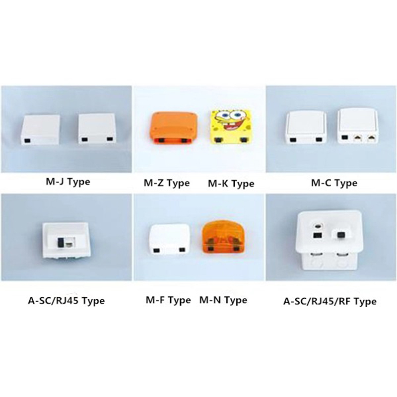
Application:It can be applied to FTTH, FTTO, FTTB applications and also has the functions of splicing, welding and installing connectors. Features:•Large variety; Full specification; Pleasing appearan...
See Details -
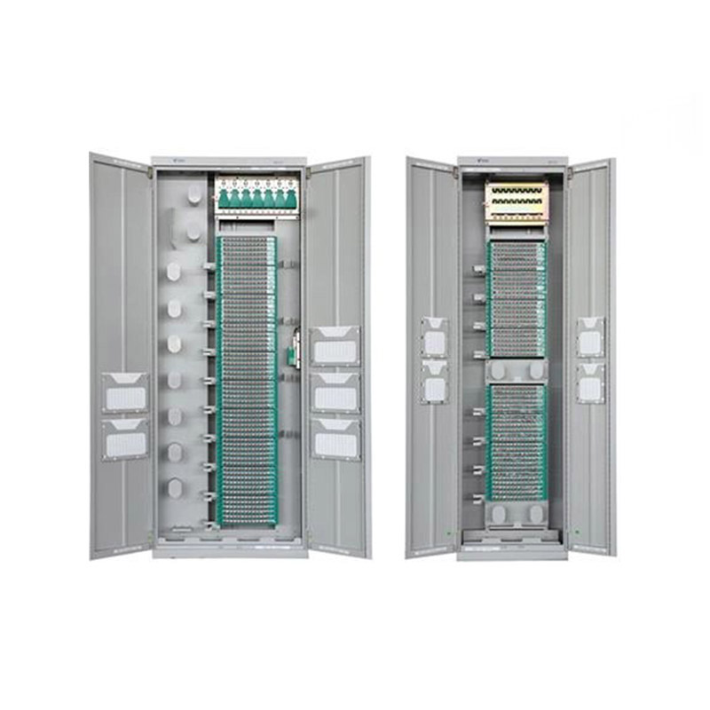
Application ScopeThe GPX129-09T fiber optic distribution frame is used to connect, distribute, and manage fiber optic cables and optical communication equipment. It is suitable for large-capacity fibe...
See Details -
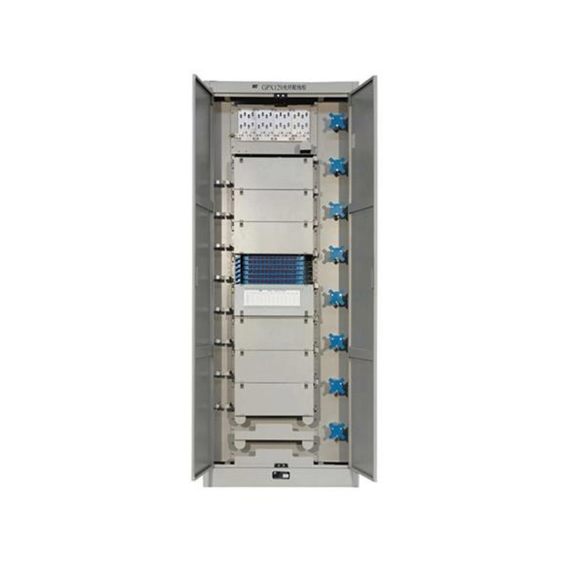
Application ScopeThe GPX129BKC fiber optic distribution frame is used to connect and distribute optical cables to optical communication equipment, and is suitable for large-capacity fiber optic commun...
See Details
Ready to Get started ? Contact Us Now !

Product.
Contact Details.
-
 +86 13958188250
-
 +86 13958188250
-
 [email protected]
-
 AUDIT Email:[email protected]
- Wanma Industrial Park Taihu Yuan Town Lin'an District Hangzhou City China.
QR Code

Copyright © Wanma Technology Co., Ltd. All Rights Reserved.
Privacy
Custom Ethernet Optical Network Railway Transit Equipments Suppliers
