

 English
 Français
 Español
 Português
 عربى







Technical data 1. Comply with various technical data of YD/T814.1-20132. Cable port:43. Cable Diameter:φ7-φ204.Max Capacity:12 Fibers 2tray=24 fibers(single)5. Sealing way: silicone rubber6. Dimension...
See DetailsEngineering a Reliable FTTH Dome Fiber Optic Splice Closure for Demanding Network Environments
Content
- 1 1. The Role of a Dome Fiber Optic Splice Closure
- 2 2. Product Overview and Main Technical Data
- 3 3. Structural Design and Material Advantages
- 4 4. IP68 Protection and Long-Term Reliability
- 5 5. Mechanical and Electrical Performance
- 6 6. Installation Versatility
- 7 7. Fiber Management and Access-Network Applications
- 8 8. Advantages Compared with Common Competing Designs
- 9 9. Manufacturing Process and Quality Control
- 10 10. Manufacturing Strength and Customized Project Support
- 11 11. Recommended Installation Procedure
- 12 12. Maintenance and Field Inspection
- 13 13. Application Selection by Installation Environment
- 14 14. Project Planning and Purchasing Considerations
- 15 15. Frequently Asked Questions
- 15.1 15.1 What type of network is the WM-2001-D01 intended for?
- 15.2 15.2 Can the closure be installed underground?
- 15.3 15.3 Can it be mounted on a wall or suspended overhead?
- 15.4 15.4 What does IP68 mean for this closure?
- 15.5 15.5 Is the product reusable after opening?
- 15.6 15.6 What cable sizes can be used?
- 15.7 15.7 What is the listed working life?
- 15.8 15.8 How should the closure be selected for freeze-thaw regions?
- 15.9 15.9 What should be checked before placing a bulk order?
- 15.10 15.10 Why is a manufacturer’s broader communication experience important?
- 16 16. Overall Evaluation
- 17 References
- 18 Product: WM-2001-D01 Dome Fiber Optic Splice Closure
Fiber access networks depend on passive infrastructure that remains reliable long after installation. While optical cables and active transmission equipment often receive the most attention, the splice closure is equally important. It protects fiber joints, organizes reserve fiber, maintains bend control, and prevents moisture, dust, mechanical damage, and environmental contamination from reaching sensitive connections. A failure in this comparatively small enclosure can interrupt service across an entire distribution segment and create costly maintenance work.
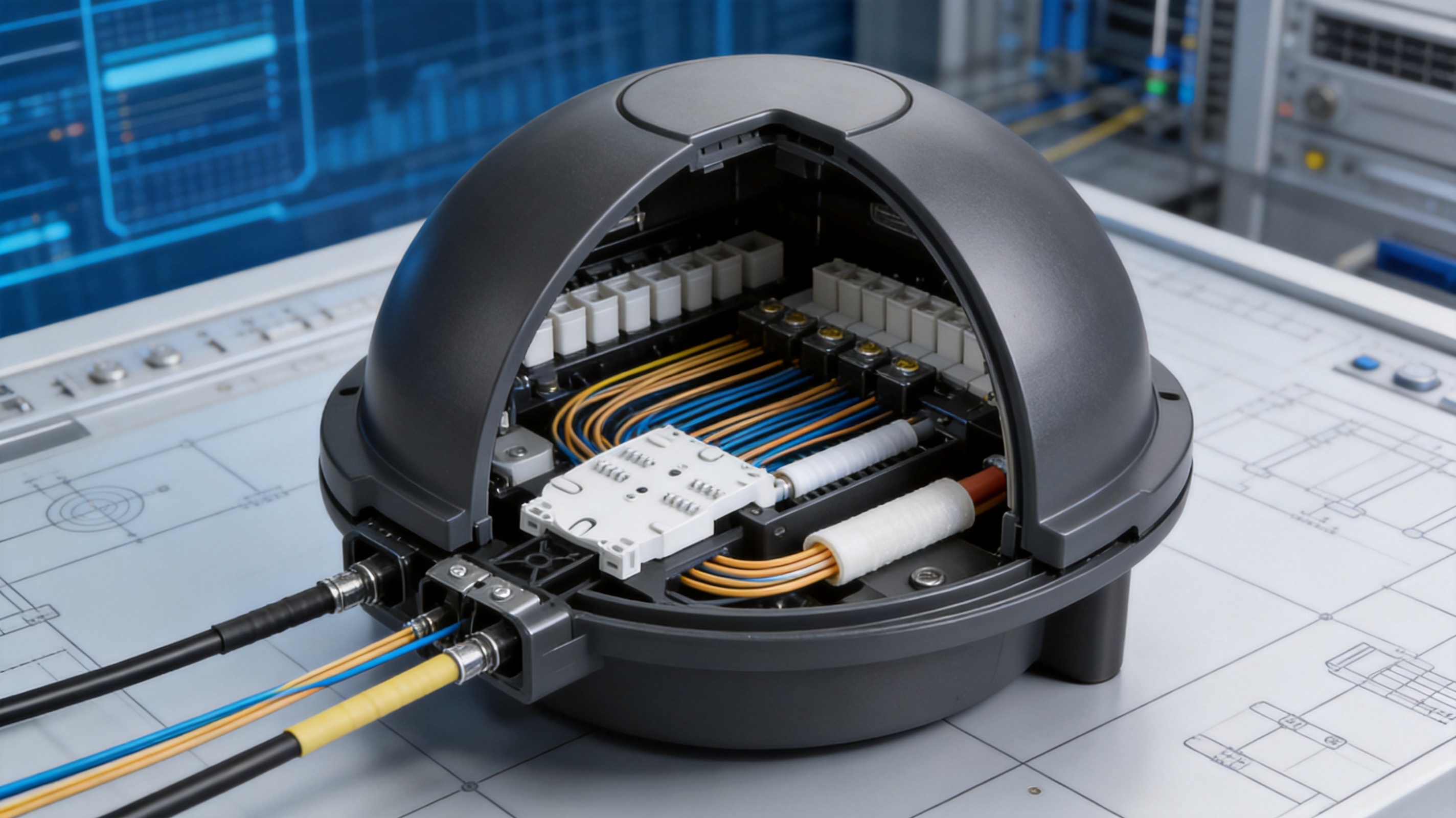
The WM-2001-D01 Dome Fiber Optic Splice Closure is designed for this role in FTTH, FTTB, and other optical communication passive networks. Its dome construction, silicone-rubber sealing system, high-strength polypropylene body, flexible installation options, and IP68 protection make it suitable for direct burial, wall-mounted, and aerial applications. The closure supports straight-through, branching, and connection arrangements while providing a compact platform for fiber splicing and protection.
This article examines the product’s technical characteristics, structural advantages, application value, manufacturing considerations, installation process, maintenance requirements, and performance in comparison with common competing closure designs. It also explains how a manufacturer with experience in communication cabinets, electronic equipment, passive optical components, railway communication systems, and Ethernet networks can support consistent product quality and customized project requirements.
1. The Role of a Dome Fiber Optic Splice Closure
A fiber optic splice closure is installed wherever optical cables must be joined, divided, repaired, or extended. The enclosure protects fusion splices and related components from water ingress, dust, impact, cable tension, temperature variation, and accidental disturbance. It also provides a controlled internal space in which fibers can be routed without violating minimum bend-radius requirements.
In an FTTH deployment, the closure may be located in a handhole, underground duct, building service area, utility corridor, pole-mounted position, or other distribution point. The environment can change considerably from one project to another. A buried closure may experience soil pressure, water accumulation, impact from stones, and freeze-thaw movement. An aerial closure may face wind, ultraviolet exposure, rain, and temperature cycling. A wall-mounted closure may be more accessible but still require dependable sealing and organized cable management.
A practical closure therefore needs more than a nominal fiber capacity. It must combine sealing performance, structural stability, installation flexibility, optical organization, serviceability, and long-term material durability. The WM-2001-D01 is developed around these combined requirements rather than around a single performance characteristic.
1.1 Protection of Optical Splices
Optical splices are highly sensitive to moisture and physical disturbance. Even when a splice itself is protected by a heat-shrinkable sleeve, the surrounding cable and fiber routing must remain stable. Water entering a closure can migrate along cable structures or collect around splice trays. Repeated movement can place stress on fibers and increase attenuation or create intermittent faults.
The dome closure provides an enclosed body for splicing and cable management. Its accessories include cable ties, heat-shrinkable tubes, PVC tubes, heat-shrinkable protection tubes, abrasive paper, alcohol paper, silver paper, and grounding-related components. These items support the preparation, securing, sealing, and protection steps required during field installation.
1.2 Support for Multiple Network Configurations
The product is intended for straight-through, diverging, and connection applications. Straight-through installation is used when a cable continues through a distribution point and selected fibers are spliced or accessed. Diverging installation is used when fibers are divided toward different routes. Connection applications may involve the joining of feeder, distribution, or drop cable sections.
This flexibility is important for FTTH and FTTB network modernization. Network planners do not always know whether a closure will be used in a simple route continuation or in a more complex branching arrangement. A closure that can support several cable configurations reduces the number of enclosure types required in inventory and simplifies project standardization.
2. Product Overview and Main Technical Data
The WM-2001-D01 is a dome-type fiber optic splice closure for optical communication passive networks. The supplied technical data identifies the product as a compact closure with a nominal diameter of approximately 85 millimeters and a length of approximately 330 millimeters. Its listed weight is about 1.5 kilograms.
The body uses high-strength PP synthetic plastic. The stated shell thickness is at least 4 millimeters. Polypropylene is widely used in outdoor communication components because it offers a useful combination of low weight, chemical resistance, electrical insulation, and processability. The selected material and wall construction are intended to provide resistance to corrosion, aging, flame exposure, and ordinary installation stresses.
The product data specifies a cable diameter range of approximately 7 to 20 millimeters and a maximum capacity of 12 single fibers, subject to the final internal configuration and project requirements. The supplied product information also identifies a cable port quantity of 43. Because cable entry arrangements can vary by configuration, purchasers should confirm the exact port allocation, fiber count, splice-tray arrangement, and cable combination before placing a project order.
| Parameter | Supplied Specification | Engineering Significance |
|---|---|---|
| Product type | Dome fiber optic splice closure | Provides an enclosed housing for optical splicing and cable routing |
| Application category | Optical communication products | Suitable for passive optical network infrastructure |
| Applicable networks | FTTH, FTTB, and related passive networks | Supports access and distribution network construction |
| Body material | High-strength PP synthetic plastic | Combines low weight, insulation, corrosion resistance, and processability |
| Shell thickness | At least 4 millimeters | Supports resistance to impact and external mechanical loading |
| Overall dimensions | Approximately 85 millimeters in diameter and 330 millimeters in length | Helps accommodate installation in compact network spaces |
| Weight | Approximately 1.5 kilograms | Facilitates handling and aerial or wall-mounted installation |
| Cable diameter range | Approximately 7 to 20 millimeters | Allows use with several common cable sizes |
| Maximum listed fiber capacity | 12 single fibers | Suitable for compact splice distribution requirements |
| Sealing method | Silicone rubber, with heat-shrinkable and adhesive sealing components | Helps maintain environmental protection around cable entries and closure joints |
| Protection rating | IP68 | Indicates a high level of dust and water-ingress protection when correctly installed and tested |
| Working life | Approximately 25 years | Supports long-term network infrastructure planning |
| Operating temperature | -40°C to +60°C | Allows deployment across a broad range of outdoor climates |
Product specifications should always be interpreted together with the installation method, cable construction, sealing components, and project environment. The performance of an assembled closure is influenced by cable preparation, tightening or shrinking procedures, cleanliness of sealing surfaces, and compliance with the manufacturer’s installation instructions.
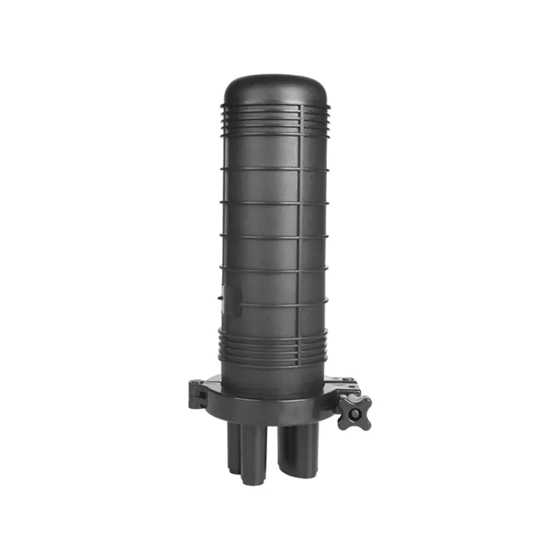
WM-2001-D01 Dome Fiber Optic Splice Closure
3. Structural Design and Material Advantages
3.1 High-Strength Polypropylene Body
The WM-2001-D01 uses high-strength polypropylene instead of a heavy metallic housing. This offers several practical advantages over closures made from unreinforced plastics or unnecessarily heavy metal structures. The lower density of PP helps reduce handling effort, transport cost, and the load imposed on poles, brackets, and aerial support systems.
Polypropylene is also electrically insulating. This is useful in communication infrastructure because the enclosure body does not normally create an unintended conductive path between cable components and external structures. In installations that require grounding or bonding, the relevant grounding components can be used according to the cable construction and applicable project standards.
The material is resistant to many common forms of corrosion. Unlike unprotected steel, it does not rust when exposed to moisture. Unlike some metallic alternatives, it does not require the same type of protective coating to prevent ordinary surface corrosion. This can be particularly valuable in wet ducts, coastal regions, industrial environments, and underground chambers.
3.2 Thick Shell Construction
The specified shell thickness of at least 4 millimeters is intended to provide a stable barrier between the internal optical components and the outside environment. A thicker shell can help the closure resist incidental impact, compression, handling damage, and deformation during installation. It also provides a more substantial surface for sealing and cable-entry components than a very thin-wall enclosure.
Wall thickness must still be balanced with flexibility. A closure that is excessively rigid may not accommodate thermal expansion or uneven sealing pressure as effectively as a carefully engineered polymer enclosure. The WM-2001-D01 combines the structural contribution of a relatively substantial shell with silicone-rubber sealing and heat-shrinkable components. This combination is designed to provide both mechanical support and sealing conformity.
3.3 Dome Configuration
The dome shape helps distribute external forces around the enclosure rather than concentrating them on broad flat panels. This geometry can be beneficial in buried or exposed installations where the body may experience uneven pressure. It also creates a compact internal volume for fiber routing and splice protection.
Dome closures are commonly selected for applications that require a vertical, end-entry, or multi-directional cable arrangement. Their form can be suitable for direct burial, aerial suspension, and wall-mounted positioning. The same general enclosure architecture can therefore be adapted to several access-network layouts.
3.4 Silicone-Rubber Sealing
The stated sealing method uses silicone rubber. Silicone-based sealing materials can remain flexible across a broad temperature range and can conform to minor surface irregularities. This is especially important when the closure is exposed to repeated expansion and contraction caused by seasonal temperature changes.
The sealing system is complemented by heat-shrinkable tubes and protection tubes. Heat-shrinkable components provide a close-fitting barrier around prepared cable sections. When heated correctly, the material contracts around the cable and sealing area, producing a secure interface. Adhesive or sticky sealing elements can further reduce the possibility of water migration through cable-entry points.
Seal performance depends on correct preparation. Cable jackets must be clean and dry, sealing surfaces must be free from dust and grease, and heat must be applied evenly. The included alcohol paper and abrasive paper are practical accessories for these preparation steps. Improper cleaning, insufficient heating, excessive heating, or incorrect cable positioning can reduce the performance of any closure regardless of its nominal IP rating.
4. IP68 Protection and Long-Term Reliability
The WM-2001-D01 is specified with an IP68 protection rating. In general terms, IP68 indicates complete protection against dust ingress and protection against prolonged immersion under conditions defined by the applicable test method. The exact immersion depth and duration should be confirmed from the manufacturer’s test report or project documentation because IP68 is not a single universal water-depth requirement for every product.
For a fiber splice closure, high ingress protection is valuable in underground ducts, handholes, manholes, and direct-burial environments. These locations may collect rainwater, groundwater, condensation, or drainage runoff. A well-sealed enclosure prevents water from reaching splice sleeves and fiber routing areas, reducing the risk of corrosion, optical attenuation changes, and service interruptions.
4.1 Balancing Sealing and Mechanical Strength
Mechanical strength and sealing performance must be engineered together. A soft seal can conform well to an irregular surface, but excessive compression may permanently deform the material. A very rigid body can withstand force, but it may transmit stress to the seal or crack under severe thermal movement. A successful closure uses compatible materials, controlled dimensions, reliable cable-entry preparation, and a sealing method suitable for the intended environment.
The product’s PP shell, silicone-rubber sealing, heat-shrinkable components, and thick-wall construction represent a balanced approach. Compared with a thin, low-cost plastic closure, the WM-2001-D01 is designed to offer greater structural stability. Compared with a heavy metal enclosure, it provides lower weight and avoids many ordinary corrosion concerns. Compared with a closure using only a hard gasket, its flexible sealing materials are better suited to accommodating small variations in cable and body dimensions.
4.2 Environmental Temperature Performance
The listed operating temperature range is -40°C to +60°C. This range covers severe winter conditions in many regions as well as hot outdoor equipment locations. Temperature performance is important because the closure body, cable jacket, heat-shrinkable material, and seal may expand at different rates.
During a cold cycle, polymer components contract. During a hot cycle, they expand. Silicone rubber and other flexible sealing elements help maintain contact during these changes. The closure should nevertheless be installed so that cable bends, cable ties, and splice trays are not placed under unnecessary tension. Thermal performance is strongest when the mechanical installation is properly controlled.
4.3 Sealing Maintenance
Even a durable closure may require seal inspection after repeated re-entry. Elastomeric materials can experience compression set over time, especially when repeatedly opened, closed, tightened, or exposed to heat. During maintenance, technicians should inspect the seal for cuts, flattening, contamination, hardening, or loss of elasticity.
Where the closure is opened for network expansion or repair, damaged sealing components should be replaced rather than reused. Cable-entry surfaces should be cleaned again, and the sealing process should follow the recommended installation sequence. Reusing a compromised heat-shrinkable component or contaminated gasket can create a leakage path that may not be immediately visible.
5. Mechanical and Electrical Performance
The supplied technical data includes a series of mechanical, environmental, and electrical test values. These values indicate the product’s intended resistance to installation and service stresses. They should be evaluated against the requirements of the target network, local regulations, and the relevant edition of the applicable industry standard.
| Test or Characteristic | Listed Value | Purpose |
|---|---|---|
| Standard reference | YD/T 814.1-2013 | Provides a technical framework for evaluating optical fiber splice closures |
| Inflation pressure for sealing test | 70 to 106 kPa | Used to assess enclosure sealing under controlled internal pressure |
| Tension | 800 N for 1 minute | Evaluates resistance to cable-pull loading |
| Compression or loading test | 2,000 N for 100 minutes | Assesses resistance to sustained external force |
| Impact test | 1-meter drop with a 1.6-kilogram steel ball, three times | Evaluates resistance to specified impact energy |
| Bending test | 150 N, ±45°, 10 cycles | Examines resistance to repeated bending loads |
| Torsion test | 50 N·m, +90°C, 10 cycles | Assesses resistance to twisting under demanding conditions |
| Insulation resistance | 2 × 10⁴ MΩ at 500 V | Indicates electrical insulation performance under the stated test condition |
| Voltage withstand | 15 kV for 1 minute at 10 mA | Evaluates insulation strength under high-voltage testing |
| Protection rating | IP68 | Indicates high resistance to dust and water ingress when tested under defined conditions |
The tension value is relevant during cable installation and maintenance. Technicians must avoid transferring excessive pulling force to the fiber splice area. Cable ties, entry seals, and internal routing components should be used to secure the cable jacket and maintain strain relief.
The compression and impact values are particularly relevant for underground work. A closure installed below ground may be exposed to backfill, accidental tool contact, movement of surrounding soil, or loading from a cover and vault. The product should still be positioned in accordance with the installation design. Direct burial does not eliminate the need for suitable bedding, drainage, protection from sharp stones, and appropriate depth.
Bending and torsion tests address movement that can occur when cables are routed at an angle, when an aerial support line shifts, or when a closure is handled during installation. These tests do not mean that cables can be bent beyond their specified limits. Instead, they demonstrate that the closure assembly is designed to tolerate defined mechanical stresses when the installation remains within its operating requirements.
6. Installation Versatility
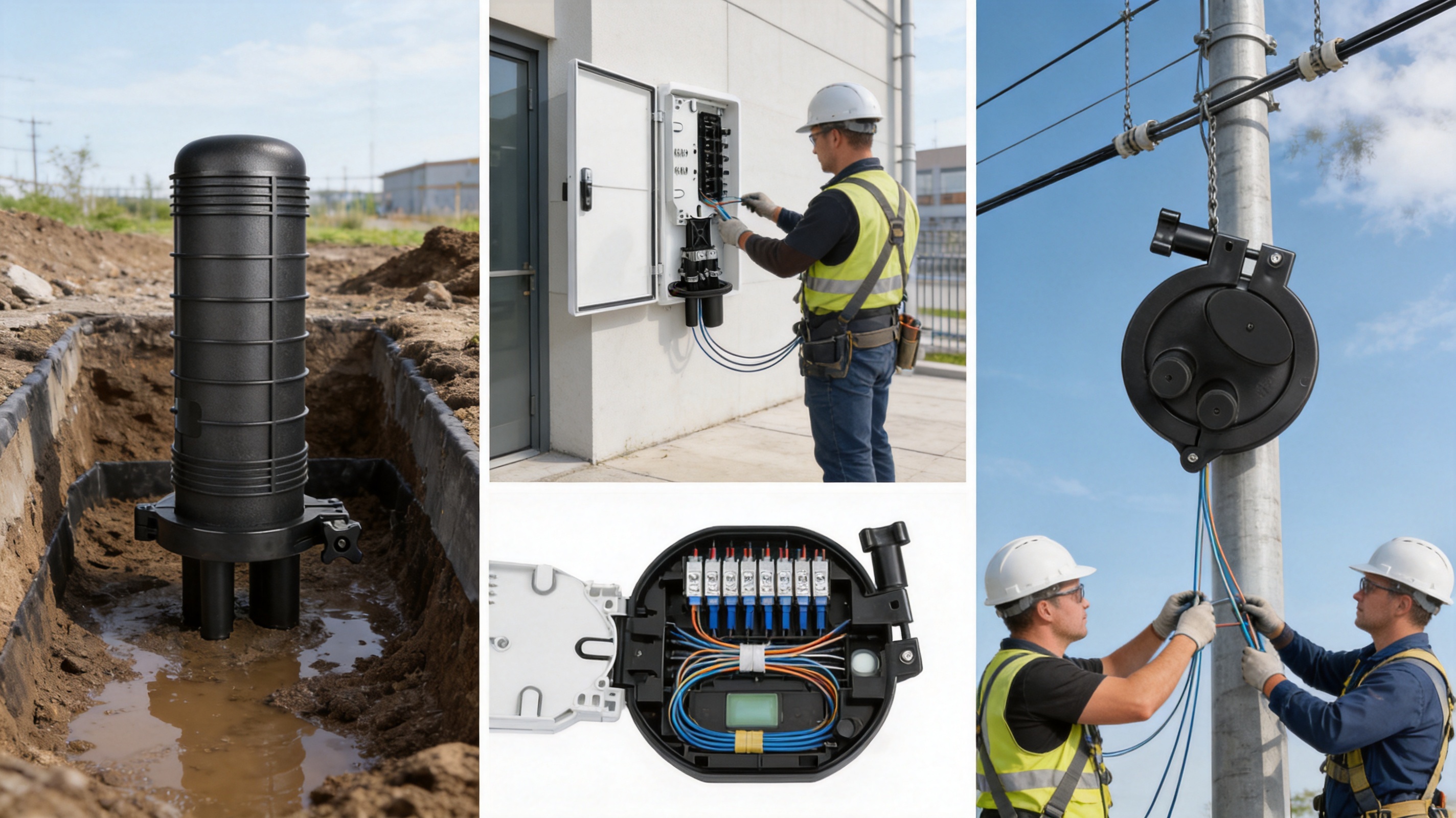
One of the product’s principal advantages is its suitability for three installation methods: direct burial, wall mounting, and aerial hanging. This versatility allows network contractors and operators to use a consistent closure platform across different sections of a project.
6.1 Direct Burial Installation
For direct burial, the closure is inflated or sealed according to the prescribed installation method and then placed underground. The surrounding soil should be free from sharp objects that could puncture or concentrate force on the enclosure. Where ground conditions are rocky, unstable, or subject to vehicle loading, the closure may require a protective vault, additional bedding, or mechanical shielding.
Direct-buried installations should be mapped and recorded accurately. The location of the closure, cable route, splice allocation, and maintenance access should be included in network documentation. Although the closure is designed for long service, future repair and expansion will be easier if the position can be found without unnecessary excavation.
6.2 Wall-Mounted Installation
For wall mounting, the supplied hanging hook can be used to fix the closure to a conduit or wall-support structure. The mounting surface should be strong enough to support the closure and cable loads. Cable paths should be arranged to avoid sharp bends, standing water, and direct strain on the cable ports.
Wall mounting is suitable for building entrances, communications rooms, utility structures, and other locations where the enclosure must remain accessible. The installer should preserve enough working space around the dome to open it safely and complete future splice maintenance.
6.3 Aerial Installation
For aerial use, the hanging hook and aerial-hanger accessories allow the closure to be suspended from a steel wire or other approved support. The support system must be designed to carry the combined weight of the closure, cables, and environmental loads such as wind and ice. Cable loops should be secured so that movement is not concentrated at the entry points.
The lightweight PP construction is particularly useful in aerial installations. Reducing the mass of passive equipment can simplify handling at height and decrease the mechanical demand on supporting hardware. However, aerial installations should also consider ultraviolet exposure, birds, wind-induced vibration, and the possibility of unauthorized access.
7. Fiber Management and Access-Network Applications
The WM-2001-D01 is intended for compact optical fiber splicing and distribution. A well-organized closure should maintain separation between incoming cables, outgoing cables, splice sleeves, and reserve fiber. Fibers should be routed smoothly with no sharp bends, crossed paths that complicate maintenance, or excessive pressure from cable ties.
In FTTH networks, the closure can be positioned between feeder and distribution segments. It may be used to branch fibers toward multiple neighborhoods, buildings, cabinets, or drop-cable routes. In FTTB networks, it can support the transition between an outdoor distribution cable and an internal building route. Its compact dimensions may be advantageous where installation space is limited.
The listed fiber capacity is suitable for small and medium splice requirements rather than very high-density central-office applications. This distinction is important when comparing products. A large closure may offer greater nominal capacity but can be unnecessarily expensive and difficult to install for a small branch point. The WM-2001-D01 is aimed at projects that value compactness, flexible mounting, and manageable fiber counts.
7.1 Straight-Through Splicing
In a straight-through arrangement, selected fibers from a cable can be spliced to corresponding fibers in another cable while unused fibers remain organized for future use. The enclosure should maintain a clear distinction between active splices and reserve fibers. Proper labeling at both cable entries reduces the risk of accidental disruption during maintenance.
7.2 Branching and Diverging
Branching applications require careful control of cable entry positions and fiber routing. The installer must identify which fibers continue along the main route and which fibers divert to a secondary cable. Cable ties and internal protection tubes can help maintain separation and prevent excessive movement.
A closure suitable for diverging arrangements can reduce the need for separate branch boxes and simplify network architecture. It can also help operators place a splice point closer to the service area, reducing the length of drop or distribution cable required.
7.3 Repair and Network Expansion
Optical networks evolve. Additional subscribers may require new splitters, distribution cables, or branch routes. A reusable dome closure can support expansion when sufficient internal space and cable-entry capability are available. The supplied product information emphasizes repeated reuse and the ability to expand capabilities.
Reuse must be performed carefully. Every re-entry should be treated as a sealing operation, not merely as a mechanical opening and closing procedure. The technician should inspect the dome, seal, heat-shrinkable parts, cable jackets, splice protectors, and internal routing before returning the closure to service.
8. Advantages Compared with Common Competing Designs
Product comparison should be based on the complete application rather than one isolated specification. Some competing closures may offer a higher nominal fiber capacity, a metal shell, a larger cable diameter range, or a different locking system. The WM-2001-D01’s advantage is its combination of compact construction, flexible installation, high ingress protection, polymer insulation, and a practical accessory package.
8.1 Compared with Thin-Wall Plastic Closures
Very thin-wall plastic closures can be lightweight and inexpensive, but they may be more vulnerable to puncture, deformation, and compression during burial. The WM-2001-D01 uses a shell thickness of at least 4 millimeters and a high-strength PP body. This provides a stronger physical barrier and greater confidence during handling and underground installation.
The thicker body may also provide more stable support for seals and cable-entry components. In a low-cost closure, deformation of the body can reduce uniform gasket compression and create leakage risks. A more substantial enclosure can maintain its shape more effectively when properly installed.
8.2 Compared with Heavy Metal Closures
Metal closures can deliver excellent mechanical strength, but they may be heavier, more expensive, and more vulnerable to corrosion if coatings or joints are damaged. The polymer construction of the WM-2001-D01 reduces weight and avoids ordinary rusting of the enclosure body. It also provides electrical insulation, which can simplify certain passive network installations.
A metal enclosure may be preferable where extreme impact or crushing loads are expected. However, many FTTH environments benefit more from balanced protection, manageable installation, and corrosion resistance than from maximum structural mass. The appropriate choice depends on soil conditions, access restrictions, expected loading, and local environmental exposure.
8.3 Compared with Closures Using Hard Gaskets Only
A hard gasket may provide strong initial compression but can be less forgiving of surface irregularities, dimensional variation, or thermal movement. The silicone-rubber sealing approach of the WM-2001-D01 is intended to maintain flexibility over a wide temperature range and to conform to sealing surfaces more effectively.
The use of heat-shrinkable tubes and sticky sealing components further supports cable-entry protection. This is useful because cable ports are often the most vulnerable part of a closure. Even a strong dome can fail if the cable-entry interface is poorly prepared or inadequately sealed.
8.4 Compared with Single-Installation Enclosures
Some closures are designed primarily for one-time installation and provide limited access for future maintenance. The WM-2001-D01 is described as reusable and expandable. This can lower the long-term cost of network ownership because technicians may be able to add branches, repair splices, or reorganize fibers without replacing the entire enclosure.
Reusability is especially valuable in developing FTTH networks. Subscriber density, building connections, and route planning often change after the initial construction phase. A closure that can accommodate controlled re-entry gives operators greater flexibility when network demand increases.
9. Manufacturing Process and Quality Control
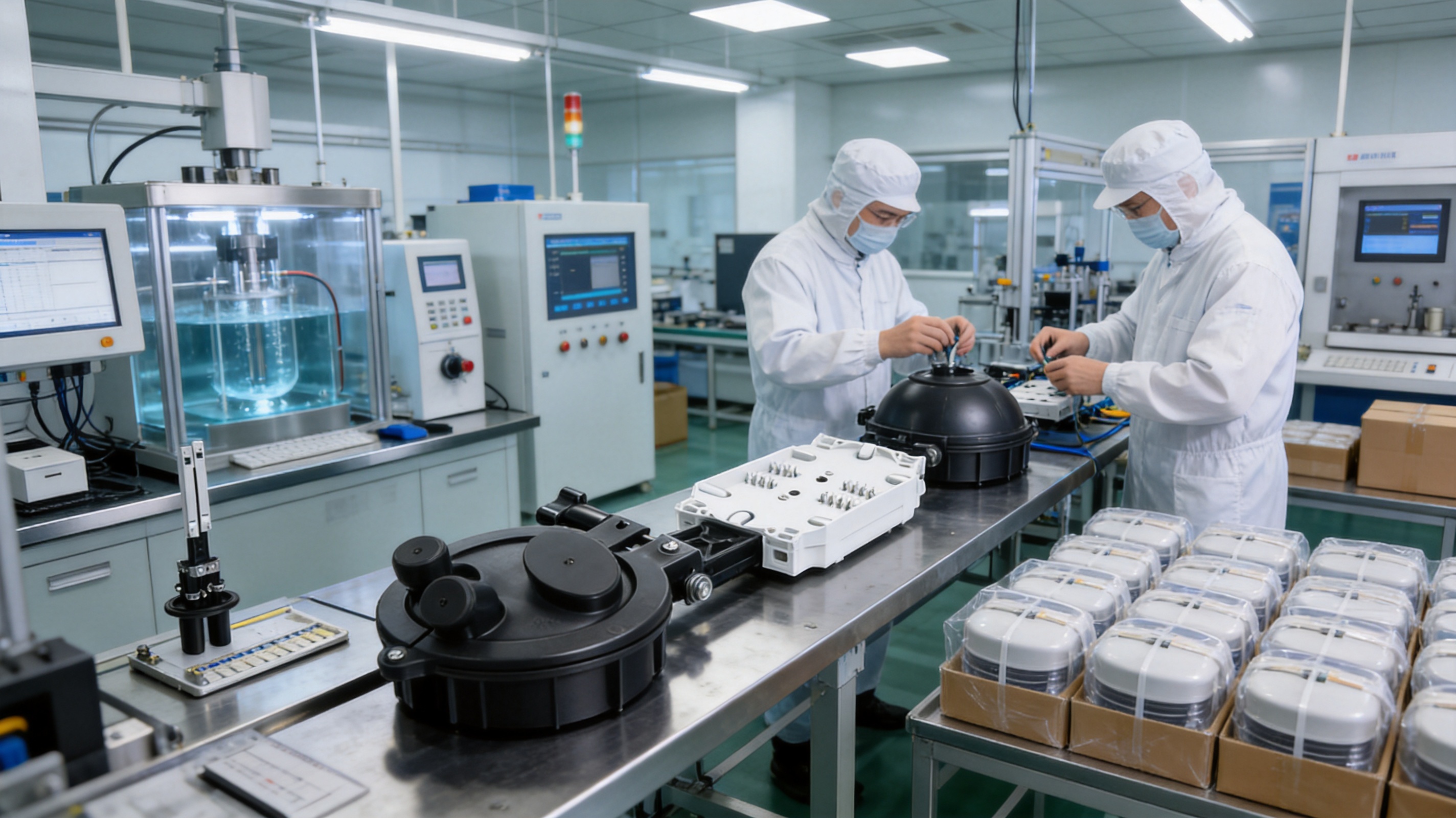
The reliability of a splice closure is influenced not only by its design but also by how consistently it is manufactured. Dimensional variation in the dome, base, cable ports, sealing grooves, or accessory interfaces can affect assembly and water resistance. A capable manufacturer therefore needs disciplined material control, tooling management, production inspection, assembly procedures, and final testing.
9.1 Material Selection and Incoming Inspection
High-strength PP resin and sealing materials should be received against defined specifications. Incoming inspection may include visual checks, identification of material batches, dimensional sampling, and verification of relevant physical characteristics. Material traceability helps manufacturers investigate quality issues and maintain consistency between production lots.
For outdoor products, the formulation should be selected with the intended temperature, moisture, aging, and flame-resistance requirements in mind. The manufacturer’s process controls should prevent contamination, incorrect material substitution, and improper storage of resin or elastomeric parts.
9.2 Molding and Dimensional Control
The dome and other polymer components are typically produced through controlled molding processes. Mold temperature, injection pressure, cooling time, and cycle consistency can influence wall thickness, shrinkage, surface finish, and dimensional stability. Proper tooling maintenance is essential because worn or damaged molds may create flash, uneven sealing surfaces, or inconsistent cable-port dimensions.
Inspection should focus on the areas most directly connected with field reliability. These include the dome-to-base interface, seal grooves, cable-port geometry, hanging-hook mounting points, and any areas subject to concentrated load. A component may appear acceptable visually while still having a dimensional deviation that affects compression or cable fit.
9.3 Assembly of Sealing Components
Sealing components must be assembled in a clean environment. Dust, oil, metal particles, or molding residue can prevent a gasket from seating correctly. Production personnel should follow standardized work instructions for installing silicone seals, heat-shrinkable components, adhesive materials, cable ties, and internal protection parts.
Where the closure uses inflation or pressure-assisted sealing procedures, the relevant interfaces should be checked for leakage. Pressure testing can identify incomplete seals, damaged components, or assembly errors before products leave the factory. The listed inflation pressure range of 70 to 106 kPa provides a reference for the supplied sealing test conditions.
9.4 Mechanical and Environmental Testing
Quality assurance should include appropriate mechanical tests such as tension, compression, impact, bending, and torsion. These tests help verify that the closure maintains its protective function when exposed to the loads expected during transportation, installation, and service.
Environmental testing may include temperature cycling, sealing checks, water-ingress evaluation, and aging assessment. Testing after thermal cycling is particularly useful because a closure that passes a room-temperature sealing test may behave differently after repeated expansion and contraction. A robust quality system evaluates the assembled product, not merely individual parts.
9.5 Electrical Testing
The listed insulation resistance and voltage-withstand values show that electrical testing is part of the product’s technical evaluation. Although the closure is primarily a passive optical product, insulation performance is important where cables, metallic strength members, grounding elements, or adjacent infrastructure create electrical exposure.
Testing equipment should be calibrated, and test records should be retained according to the manufacturer’s quality procedures. Clear test documentation helps customers evaluate product suitability for rail transit, industrial, municipal, and telecommunications projects.
9.6 Final Inspection and Packaging
Before shipment, each closure should be checked for appearance, completeness, accessory quantity, labeling, dimensions, and packaging integrity. Accessories such as cable ties, tubes, aerial-hanger components, protection tubes, silver paper, alcohol paper, and abrasive paper should be packed so that installers receive the complete field kit.
Packaging must protect the dome from impact, deformation, dust, and moisture during transportation. Clear product identification supports warehouse control and reduces the chance of mixing different capacities or configurations on a construction site.
10. Manufacturing Strength and Customized Project Support
Wanma Technology Co., Ltd. was established in 1997 and specializes in communication cabinets, communication electronic equipment, and passive optical components. This background is relevant to splice-closure customers because it reflects experience across the wider communication infrastructure chain rather than in a single isolated product category.
The company’s products are used in Ethernet networks, optical communication networks, central equipment rooms, national high-speed railways, and urban rail transit systems. These application areas require attention to mechanical reliability, installation repeatability, environmental protection, documentation, and delivery coordination. Experience in such fields can support the development of products for demanding outdoor and infrastructure environments.
The company develops, manufactures, and markets its own branded products while also providing integrated solutions for customized products. For customers with special cable combinations, mounting methods, labeling requirements, packaging needs, or network architectures, this capability can simplify communication between design and production teams.
Customization should be managed through a structured engineering process. The customer and manufacturer should define cable diameter, entry quantity, fiber count, splice organization, installation orientation, environmental temperature, burial conditions, mounting hardware, grounding requirements, and test documentation. These details should be confirmed before tooling changes or mass production begin.
A manufacturer with in-house product development and production coordination can also support design improvements based on field feedback. For example, recurring installation problems may lead to revised cable-entry parts, clearer markings, stronger hanging hardware, improved accessory packaging, or updated instructions. This continuous-improvement approach helps convert service experience into product value.
Wanma Technology emphasizes reliable product quality, timely delivery, and long-term strategic partnerships. Its sales network covers more than 20 countries and regions, including the United States, Australia, the United Kingdom, Italy, South Africa, and Ghana. International project support requires more than product availability; it also requires consistent communication, export coordination, technical clarification, and the ability to work with different installation standards and customer expectations.
11. Recommended Installation Procedure
The exact installation method should follow the manufacturer’s supplied instructions. The following sequence provides a general framework for planning and field execution.
11.1 Prepare the Work Area
Before opening the product package, confirm the closure model, accessory list, cable sizes, splice plan, tools, heat source, cleaning materials, labels, and safety equipment. Select a work area that is clean, dry, and protected from excessive wind, rain, and dust. In underground construction, prevent mud or standing water from entering the closure during preparation.
11.2 Inspect the Cables
Check the cable jackets for cuts, crushing, moisture, or other damage. Confirm that the cable diameters are within the product’s listed range. Identify the cable direction, required branch points, fiber assignments, and reserve lengths before removing or preparing the cable sheath.
11.3 Prepare Cable Entries
Cut and prepare the cable ends according to the required splice length. Remove the appropriate jacket sections without damaging buffer tubes, fibers, metallic strength members, or grounding components. Use the supplied abrasive paper and alcohol paper where appropriate to prepare surfaces for sealing and heat-shrinkable components.
11.4 Organize and Secure Fibers
Route fibers with smooth curves and preserve the specified minimum bend radius. Position splice sleeves in the appropriate protection area and use PVC tubes or other supplied protection components where required. Cable ties should secure the cable jacket or protective elements without compressing optical fibers.
11.5 Complete the Sealing System
Install silicone-rubber seals, heat-shrinkable tubes, and sticky sealing materials in the specified order. Apply heat evenly and avoid burning the cable jacket or overheating the seal. Ensure that every cable-entry point is fully seated and that no visible gap, wrinkle, contamination, or trapped object remains in the sealing interface.
11.6 Close and Test the Assembly
Close the dome carefully and verify that the body and sealing surfaces are correctly aligned. If the installation method requires inflation, apply the specified pressure and monitor the assembly for leakage. The closure should be visually inspected before burial, mounting, or aerial suspension.
11.7 Record the Installation
Document the closure location, cable identifiers, splice assignments, installation date, test results, and technician information. Photographing cable routing and sealing areas before final closure can provide valuable maintenance evidence. Accurate records reduce future service time and help operators locate the correct closure during network expansion.
12. Maintenance and Field Inspection
A well-installed closure requires limited routine maintenance, but it should remain part of the network asset-management program. Inspection intervals depend on the environment and network importance. Flood-prone underground locations, coastal areas, railway corridors, and high-vibration installations may deserve more frequent checks than protected wall-mounted sites.
During inspection, technicians should look for cracks, deformation, loose mounting hardware, damaged cable jackets, corrosion on metallic accessories, signs of water accumulation, and evidence of animal or mechanical damage. Aerial closures should also be checked for support-wire condition, hanging-hook security, cable sag, and wind movement.
When a closure is reopened, the internal arrangement should be restored carefully. Fibers must not be pulled, sharply bent, or trapped between mating surfaces. The seal should be cleaned or replaced as required. All cable ports should be checked, including ports that are not currently occupied, because unused openings can become an ingress path if not properly closed.
For critical installations, a pressure or vacuum decay test can be performed after maintenance. A field vacuum test may involve drawing a vacuum of approximately 0.5 bar and monitoring pressure stability for a defined period. A pressure drop of less than 2 kPa over five minutes has been suggested as an indication of good sealing in the supplied technical discussion, but the acceptance value should be confirmed against the project’s approved test procedure.
13. Application Selection by Installation Environment
13.1 Underground and Direct-Burial Networks
Underground use places emphasis on sealing, compression resistance, impact resistance, and long-term material stability. The IP68 specification is valuable where water tables rise or ducts are periodically flooded. The thick PP shell and listed mechanical tests provide a basis for evaluating resistance to ordinary underground handling and loading.
In rocky soil or areas exposed to heavy vehicle loading, additional protection may still be necessary. A concrete vault, protective box, suitable bedding, or external armor can reduce concentrated stress. The closure should not be treated as a substitute for an engineered underground chamber where extreme loads are expected.
13.2 Manholes and Flooded Ducts
Manholes and flooded ducts require strong water-ingress protection because the closure may be exposed to standing water for extended periods. The IP68 rating and silicone-rubber sealing system are appropriate characteristics for this environment, provided the assembly is installed and tested correctly.
Technicians should consider access space, drainage, cable routing, and the possibility of repeated maintenance. A compact closure can make work easier in a confined manhole, but sufficient working clearance must be retained around the dome and cable entries.
13.3 Aerial Fiber Networks
Aerial installations place more emphasis on weight, mounting security, ultraviolet exposure, wind movement, and cable strain. The approximately 1.5-kilogram weight and supplied aerial-hanger accessories support practical suspension. The closure should be mounted so that cable tension is transferred to the support system rather than to the fiber splice area.
Even where water pressure is not the primary risk, a high level of sealing remains useful because rain, condensation, and airborne contamination can enter poorly protected enclosures. Routine inspection should focus on UV-related aging, loose hardware, and movement of the closure or cable.
13.4 Wall-Mounted and Building Applications
Wall-mounted applications often provide better access and lower exposure to crushing forces. They may be found at building entrances, service corridors, utility rooms, and telecommunications distribution points. The hanging-hook arrangement enables installation without requiring a large support frame, while the compact dimensions help conserve wall space.
Indoor or semi-outdoor locations may not require the full environmental performance available from IP68, but the added protection can improve reliability where walls are exposed to washdown, condensation, or outdoor weather.
14. Project Planning and Purchasing Considerations
Before selecting the WM-2001-D01 for a project, engineering teams should confirm the required splice count, cable diameter, port arrangement, installation orientation, environmental temperature, burial depth, expected mechanical loading, and maintenance plan. The listed maximum capacity should not be exceeded, and sufficient reserve space should be maintained for safe routing.
Purchasers should request the current technical drawing, installation manual, accessory list, test documentation, and any available compliance records. If a project requires a specific version of YD/T 814.1 or another national or operator standard, the applicable test scope should be confirmed in writing.
For international projects, it is also useful to specify packaging language, product labels, cable-entry markings, spare sealing components, inspection records, and delivery batches. Standardized documentation can simplify acceptance testing and make the product easier for local installation teams to use.
Where the network is expected to expand, customers should discuss future cable-entry requirements and re-entry procedures at the quotation stage. A closure that satisfies the initial fiber count may not provide enough room for later branches if the expansion plan is not considered in advance.
15. Frequently Asked Questions
15.1 What type of network is the WM-2001-D01 intended for?
The closure is intended for FTTH, FTTB, and other optical communication passive networks. It can support straight-through, branching, and connection applications in access and distribution infrastructure.
15.2 Can the closure be installed underground?
Yes. The supplied installation methods include direct burial after the closure has been sealed or inflated according to the required procedure. Underground installation should include suitable bedding, protection from sharp stones, accurate location records, and appropriate mechanical protection where heavy loads are expected.
15.3 Can it be mounted on a wall or suspended overhead?
Yes. The product can be wall-mounted using its hanging hook and can be suspended from a steel wire using aerial-hanger accessories. The mounting structure must be strong enough to support the enclosure, cables, and environmental loads.
15.4 What does IP68 mean for this closure?
IP68 indicates dust-tight construction and protection against prolonged immersion under defined test conditions. The exact water depth and test duration should be verified from the applicable product test report because IP68 conditions may vary between standards and manufacturers.
15.5 Is the product reusable after opening?
The product is designed for repeated reuse and capability expansion. However, re-entry must be followed by careful inspection and, when necessary, replacement of gaskets, heat-shrinkable components, or other sealing parts. A closure should not be assumed to retain its original sealing performance if the seal has been damaged or permanently deformed.
15.6 What cable sizes can be used?
The supplied technical data lists a cable diameter range of approximately 7 to 20 millimeters. The exact compatibility should be confirmed for the selected cable construction and cable-entry configuration before installation.
15.7 What is the listed working life?
The listed working life is approximately 25 years. Actual service life depends on ultraviolet exposure, temperature, water chemistry, mechanical loading, installation quality, maintenance frequency, and the condition of sealing components.
15.8 How should the closure be selected for freeze-thaw regions?
Choose a configuration with flexible sealing materials, verify the body material’s low-temperature suitability, and ensure that the closure is tested after thermal cycling where required. Installation should prevent water from remaining in unwanted internal or cable-entry spaces, because freezing water can create damaging expansion pressure.
15.9 What should be checked before placing a bulk order?
Confirm the technical drawing, dimensions, cable-port arrangement, fiber capacity, accessories, sealing process, applicable standards, test records, packaging, delivery schedule, and any customization requirements. A sample installation and sealing test can reduce risk before full-scale deployment.
15.10 Why is a manufacturer’s broader communication experience important?
A manufacturer experienced in communication cabinets, electronic equipment, passive optical components, Ethernet networks, railway systems, and urban rail transit is familiar with the reliability and documentation expectations of network infrastructure. This broader experience can support product consistency, customization, integrated solutions, and long-term technical cooperation.
16. Overall Evaluation
The WM-2001-D01 Dome Fiber Optic Splice Closure is a practical solution for compact fiber splice protection in FTTH, FTTB, and related optical communication networks. Its key strengths include a high-strength PP body, shell thickness of at least 4 millimeters, silicone-rubber sealing, heat-shrinkable cable-entry protection, IP68-rated protection, flexible mounting options, and a listed working life of approximately 25 years.
Compared with thin-wall plastic alternatives, the product emphasizes stronger body construction and greater resistance to handling and external loading. Compared with heavy metal designs, it offers lower weight, electrical insulation, and resistance to ordinary rusting. Compared with closures that rely on hard gaskets alone, its silicone-rubber and heat-shrinkable sealing approach provides a more adaptable interface across temperature changes and cable-entry conditions.
The product is most valuable when its balanced characteristics match the installation environment. It is suitable for underground, wall-mounted, and aerial deployment, but each application still requires appropriate support, cable preparation, mechanical protection, and testing. The closure’s performance depends on the complete installation system, not only on the enclosure body.
Wanma Technology Co., Ltd. adds value through its long-term involvement in communication infrastructure, passive optical components, electronic equipment, Ethernet networks, railway systems, and urban rail transit applications. Its manufacturing, product-development, customized-solution, and international-sales capabilities provide a foundation for customers seeking both a standardized splice closure and broader project support.
For network operators, contractors, system integrators, and telecommunications distributors, the WM-2001-D01 offers a combination of environmental protection, manageable installation, material durability, and application flexibility. When correctly specified, installed, tested, and maintained, it can contribute to stable optical access networks and reduce the long-term risks associated with water ingress, mechanical damage, and difficult splice-point servicing.
References
1. YD/T 814.1-2013, technical requirements and test considerations for optical fiber splice closures.
2. IEC 60529, Degrees of Protection Provided by Enclosures, including IP code classification.
3. International optical fiber installation practices for cable preparation, splice protection, bend-radius control, and enclosure maintenance.
4. Manufacturer-supplied technical data for the WM-2001-D01 Dome Fiber Optic Splice Closure.
5. Manufacturer-supplied product information concerning installation methods, accessories, sealing procedures, and application environments.
6. General engineering principles for polymer enclosure design, elastomeric sealing, thermal cycling, mechanical testing, and passive optical network infrastructure.
Product: WM-2001-D01 Dome Fiber Optic Splice Closure
PREV:Advanced Fiber Access Distribution for Outdoor FTTH Networks
NEXT:Engineering Guide to High-Capacity Horizontal Fiber Optic Splice Closures
NEXT:Engineering Guide to High-Capacity Horizontal Fiber Optic Splice Closures
Interested in cooperation or have questions?
Related products
-
-
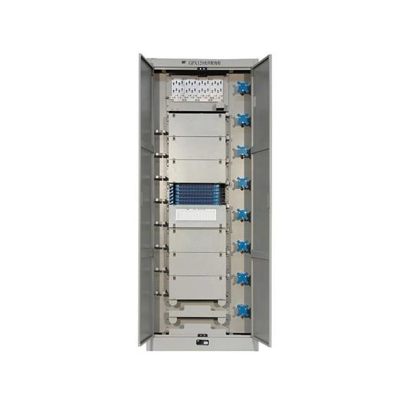
Application ScopeThe GPX129BKC fiber optic distribution frame is used to connect and distribute optical cables to optical communication equipment, and is suitable for large-capacity fiber optic commun...
See Details -
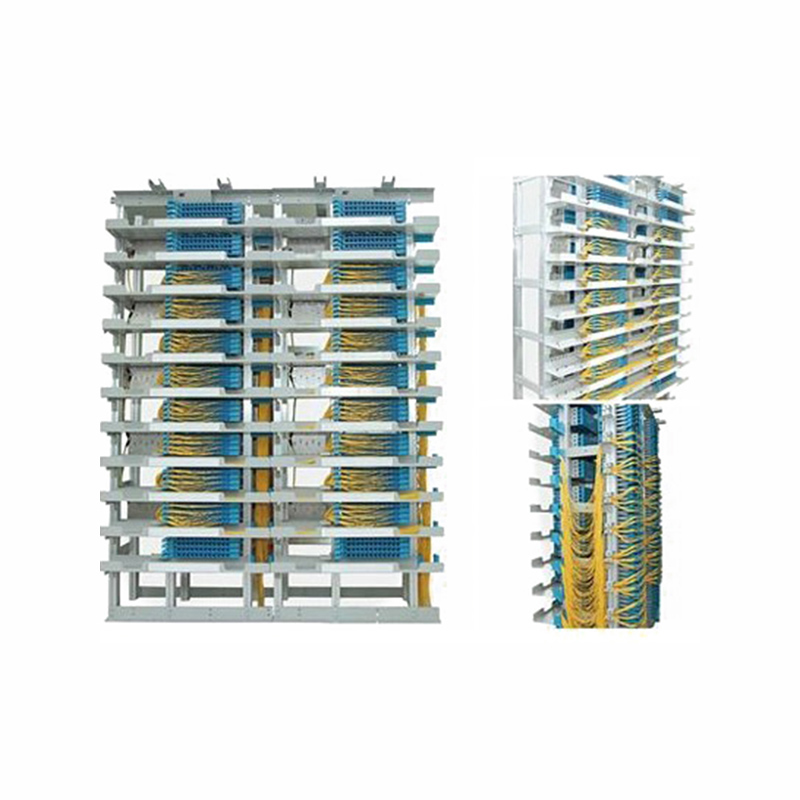
Application Used in independent fiber patching areas of newly built communication equipment rooms and central equipment rooms. After cable removal, the original main distribution frame is dismantled, ...
See Details -
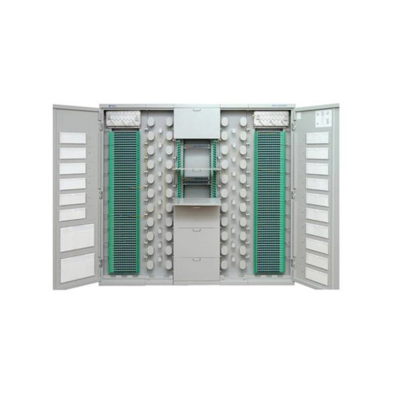
Application Used in FTTH network access-layer equipment rooms where splitting, splicing, distribution and other operations need to be carried out within a frame. Used in FTTH networks where optical sp...
See Details
Ready to Get started ? Contact Us Now !

Product.
Contact Details.
-
 +86 13958188250
-
 +86 13958188250
-
 [email protected]
-
 AUDIT Email:[email protected]
- Wanma Industrial Park Taihu Yuan Town Lin'an District Hangzhou City China.
QR Code

Copyright © Wanma Technology Co., Ltd. All Rights Reserved.
Privacy
Custom Ethernet Optical Network Railway Transit Equipments Suppliers
