

 English
 Français
 Español
 Português
 عربى





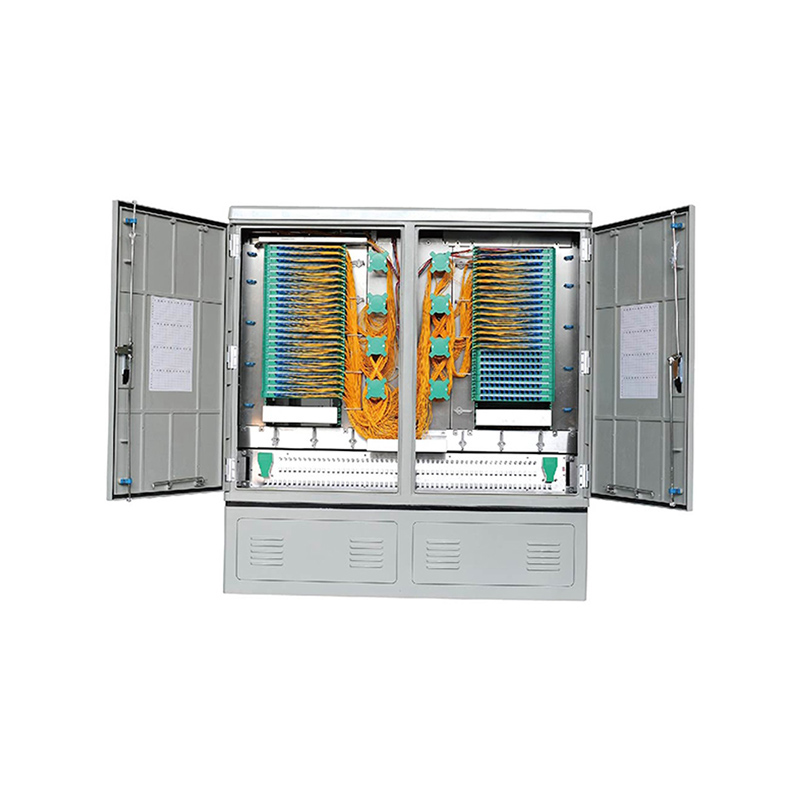

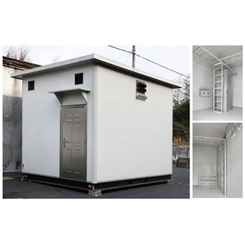

Application:It can be applied to FTTH, FTTO, FTTB applications and also has the functions of splicing, welding and installing connectors. Features:•Large variety; Full specification; Pleasing appearan...
See DetailsEngineering Guide to High-Capacity Horizontal Fiber Optic Splice Closures
Content
- 1 1. The Role of a Fiber Optic Splice Closure in Modern Networks
- 2 2. Product Overview
- 3 3. Capacity and Internal Organization
- 4 4. Sealing and Environmental Protection
- 5 5. Mechanical Strength and Durability
- 6 6. Electrical Insulation and Protection
- 7 7. Installation Flexibility
- 8 8. Installation Procedure and Best Practices
- 9 9. Basic Accessories and Their Functions
- 10 10. Competitive Advantages in Practical Deployment
- 11 11. Manufacturing Strengths and Process Control
- 12 12. Applications in FTTH and FTTB Networks
- 13 13. Applications in Ethernet, Railway, and Transit Infrastructure
- 14 14. Applications in Industrial and Outdoor Environments
- 15 15. Maintenance and Long-Term Reliability
- 16 16. Procurement Considerations
- 17 17. Why Manufacturing Experience Matters to Buyers
- 18 18. Recommended Quality-Control Checklist
- 19 19. Sustainability and Life-Cycle Value
- 20 20. Selection Summary
- 21 21. Questions and Answers
- 21.1 Q1: What type of product is the WM-2001-D10?
- 21.2 Q2: What is its maximum stated fiber capacity?
- 21.3 Q3: Can the closure be used for FTTH and FTTB?
- 21.4 Q4: What sealing method does it use?
- 21.5 Q5: Is it suitable for outdoor installation?
- 21.6 Q6: Can it be buried underground?
- 21.7 Q7: Can it be mounted on a wall or suspended aerially?
- 21.8 Q8: What is the shell made from?
- 21.9 Q9: Is the closure reusable?
- 21.10 Q10: Which accessories are included?
- 21.11 Q11: What should be confirmed before purchase?
- 21.12 Q12: Why is supplier manufacturing experience important?
- 22 Conclusion
- 23 References
- 24 Product: WM-2001-D10 Fiber Optic Splice Closure
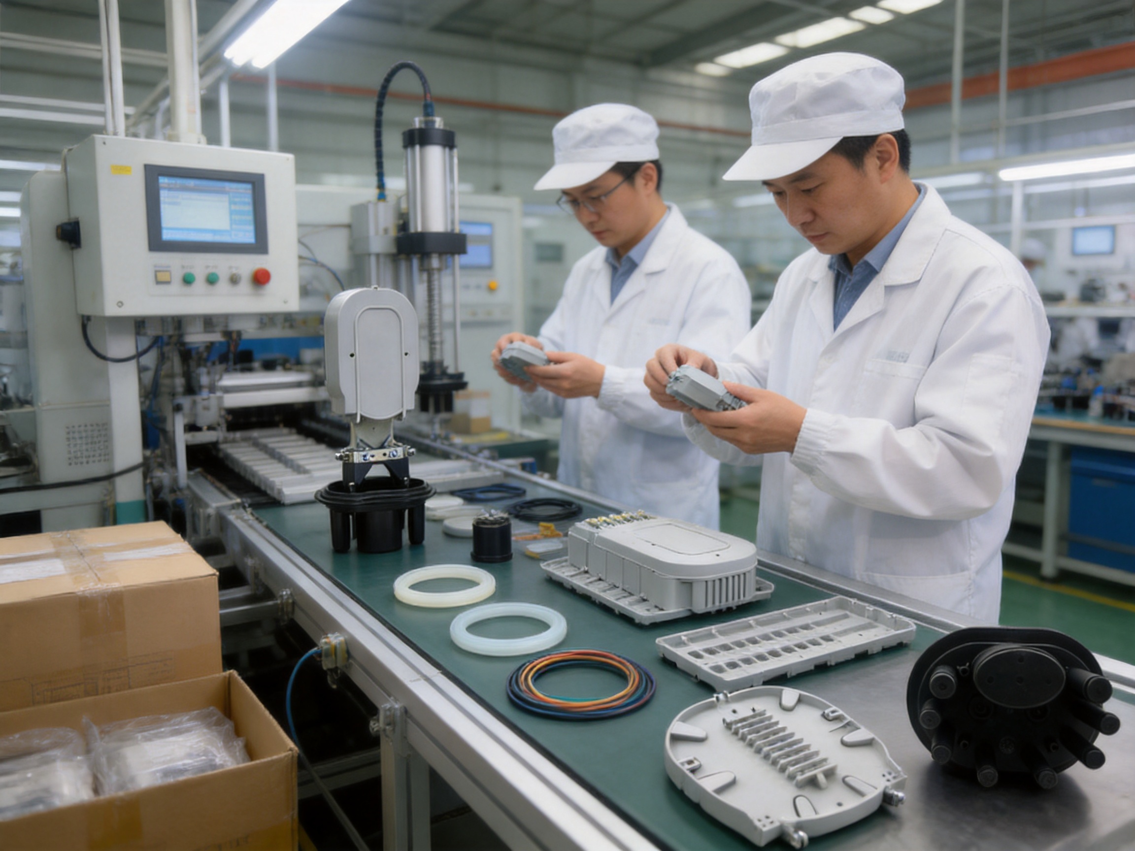
Fiber optic networks depend on thousands of connection points that must remain stable despite moisture, mechanical stress, temperature changes, dust, vibration, and repeated maintenance activity. A splice closure is one of the most important protective components in this infrastructure. It preserves the continuity of optical fibers, protects fusion splices, organizes cable entries, and provides a secure transition between buried, wall-mounted, and aerial sections of a network.
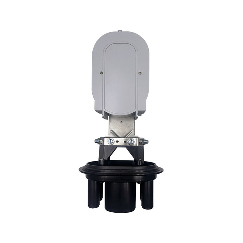
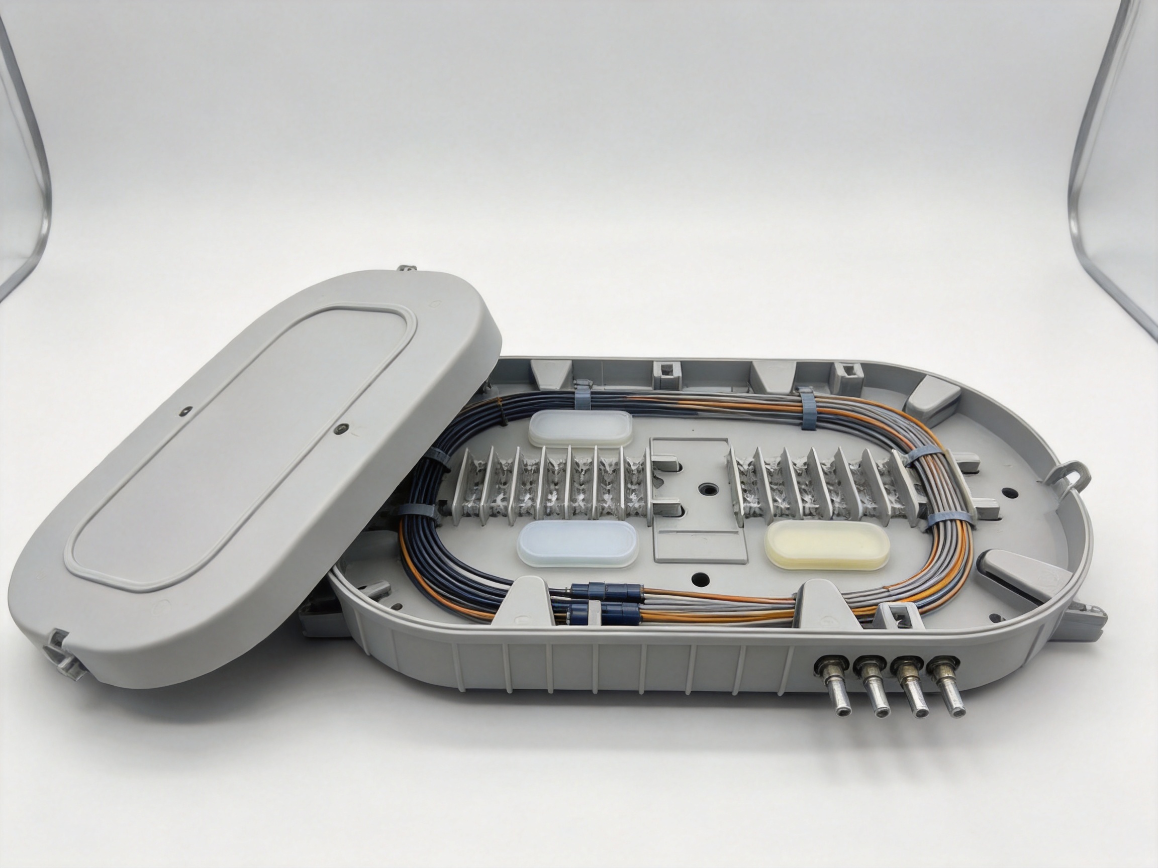
The WM-2001-D10 fiber optic splice closure is a horizontal enclosure designed for straight-through, branching, and connection applications in FTTH, FTTB, Ethernet, and other optical communication passive networks. It combines a high-capacity internal structure with silicone-rubber sealing, heat-shrinkable protection, a durable synthetic-plastic shell, and installation flexibility. Its stated maximum capacity is 288 single fibers, making it suitable for dense access networks and distribution points where space, reliability, and future expansion are important.
This article examines the product’s construction, performance, installation methods, applications, competitive advantages, manufacturing considerations, quality requirements, and maintenance value. It also explains how an experienced communication-equipment manufacturer can support the product through design control, material selection, assembly discipline, testing, customization, and project coordination.
1. The Role of a Fiber Optic Splice Closure in Modern Networks
Optical fiber provides high bandwidth, low signal loss, and strong resistance to electromagnetic interference. However, the bare fiber and its fusion-splice points are relatively delicate. A splice closure creates a controlled environment around these points. It prevents water and contaminants from reaching the splice area, manages fiber bending, protects cable strength members, and allows technicians to perform future maintenance without replacing an entire cable section.
In a typical FTTH network, a feeder cable may enter a closure and be connected to one or more distribution cables. In an FTTB installation, the closure can serve a building or group of buildings. In an Ethernet or railway communication network, it may be positioned in a trackside cabinet, equipment area, manhole, wall-mounted distribution point, or outdoor route. The closure must therefore perform reliably across different installation environments rather than serving only one narrow application.
A well-designed closure must address several engineering requirements at the same time. It should provide adequate internal capacity, maintain an organized fiber-routing path, prevent excessive bending, protect cable entry points, withstand impact and tension, and remain serviceable after installation. It should also be compatible with common construction practices so that contractors can install it efficiently in the field.
The horizontal form factor is particularly useful when fibers need to be arranged in trays or organized across a relatively broad internal working area. Compared with a compact vertical closure, a horizontal closure can offer convenient access to splice trays and cable-routing channels. This can simplify fiber identification, splicing, testing, and later expansion.
2. Product Overview
The WM-2001-D10 is specified as a horizontal fiber optic splice closure for passive optical communication networks. The product is intended for straight-through, diverging, and connection applications. It can be directly buried after inflation and sealing, fixed to a wall using a hanging hook, or suspended from an aerial steel wire with an appropriate hanging arrangement.
The stated technical profile includes a maximum capacity of 288 single fibers, a silicone-rubber sealing method, a shell made from high-strength PP synthetic plastic, a shell thickness of at least 4 millimeters, and an IP68 protection rating. The listed dimensions are approximately 470 by 230 millimeters, with a stated weight of approximately 2.5 kilograms.
The product is specified for an operating environment from -40°C to +60°C. Its stated working life is 25 years, subject to correct installation, appropriate environmental conditions, and normal maintenance practices. The design includes reusable characteristics, enabling technicians to reopen the closure for repair, re-entry, or capacity expansion instead of discarding the entire enclosure after one intervention.
| Item | Stated Specification | Engineering Significance |
|---|---|---|
| Product type | Horizontal fiber optic splice closure | Provides a broad internal arrangement for splice organization and maintenance |
| Maximum capacity | 288 single fibers | Supports dense distribution and future network growth |
| Shell material | High-strength PP synthetic plastic | Offers a lightweight protective enclosure with resistance to corrosion and aging |
| Shell thickness | At least 4 mm | Contributes to structural protection and insulation |
| Sealing method | Silicone rubber, with heat-shrinkable and adhesive sealing arrangements | Helps protect the splice area against water, dust, and environmental intrusion |
| Protection rating | IP68 | Indicates a design intended for high-level dust and water protection when correctly installed |
| Operating temperature | -40°C to +60°C | Supports outdoor and infrastructure applications in demanding climates |
| Approximate dimensions | 470 × 230 mm | Balances internal capacity with field handling requirements |
| Approximate weight | 2.5 kg | Helps simplify transport, positioning, and installation |
| Stated working life | 25 years | Aligns with long-term telecommunications infrastructure planning |
3. Capacity and Internal Organization
Capacity is one of the most important factors when selecting a splice closure. A closure that is only large enough for the initial number of fibers may become difficult to maintain when a network expands. Technicians may need to add cables, install additional splice trays, reroute fibers, or replace damaged sections. A high-capacity design provides greater flexibility and can reduce the need for premature enclosure replacement.
With a stated maximum capacity of 288 single fibers, the product is intended for high-density applications. This capacity can be valuable in feeder distribution, multi-building FTTH deployment, industrial communication networks, railway corridors, and urban access systems. It may also support a mixture of through-splicing and branch-splicing arrangements, depending on the selected internal accessories and the cable construction used in a particular project.
Capacity alone does not determine practical performance. The internal layout must also allow fibers to be routed without sharp bends, compression, or confusion between circuits. A properly planned installation should reserve a suitable amount of fiber slack, identify each cable and splice group, and maintain a clear path for future work. The horizontal configuration supports this type of organized working method because the technician can access the internal area directly after opening the enclosure.
Fiber management is especially important in high-count networks. Poorly arranged fibers can increase the risk of microbending, accidental pulling, incorrect reconnection, or excessive maintenance time. The closure should therefore be installed with attention to tray orientation, bend-radius requirements, cable-strength-member fixation, and separation between active work areas and reserve fiber.
The reusable structure also provides a practical advantage over closures intended for one-time installation. Network projects rarely remain static for their entire life. Operators may add subscribers, reroute distribution paths, replace cable sections, or introduce new access technologies. A closure that can be reopened and resealed gives the network operator more options and can lower long-term operating expenditure.
WM-2001-D10 Fiber Optic Splice Closure
4. Sealing and Environmental Protection
Water ingress is one of the most serious threats to optical splice reliability. Even small amounts of moisture can accelerate corrosion in metallic components, affect cable strength members, contaminate splice protection sleeves, and create conditions that may lead to long-term optical degradation. A splice closure must therefore provide a reliable barrier around the enclosure body and each cable entry.
The product uses silicone rubber as part of its sealing approach. Silicone rubber is widely used in outdoor communication equipment because it can maintain elasticity across a broad temperature range and can accommodate small dimensional changes caused by thermal expansion. This is important when the enclosure and cable jackets expand or contract at different rates.
The product description also identifies heat-shrinkable sealing and adhesive sealing arrangements. Heat-shrinkable components can form a close fit around cable entry areas when heated correctly. Adhesive sealing materials can help fill surface irregularities and improve resistance to moisture migration. The effectiveness of these systems depends on correct preparation, including cleaning, cable-jacket inspection, correct heating, and complete circumferential contact.
The stated IP68 rating represents a high level of protection against dust and water under the applicable test conditions. It should not be interpreted as permission to ignore installation procedures. An enclosure can lose its intended protection if the cable port is damaged, a seal is contaminated, a heat-shrinkable tube is incompletely recovered, or the closure is reopened without proper resealing.
The inflation-related specifications in the product data indicate a sealing verification approach involving internal pressure. The listed inflation pressure is 70–106 kPa, with an environmental pressure reference of 100 kPa over 24 hours. These figures should be confirmed against the manufacturer’s current test documentation and the exact project inspection procedure before formal acceptance.
For buried installations, sealing quality is particularly important because the closure may be exposed to groundwater, soil movement, seasonal temperature changes, and occasional mechanical loading. For aerial installations, the enclosure must also resist rain, wind-driven moisture, ultraviolet exposure, and vibration transmitted through the supporting wire. Wall-mounted installations may experience splash water, dust, and building-related movement.
5. Mechanical Strength and Durability
Communication closures are exposed to mechanical forces during transportation, installation, maintenance, and service. The product data lists several mechanical and environmental tests, including tension, pressure or loading, impact, bending, and torsion. Together, these tests address different types of stress that may occur in practical deployment.
The stated tension test is 800 N for one minute. This type of test relates to the ability of the closure and its cable-retention arrangements to withstand axial force. Proper cable fixation is essential because pulling force should be transferred to the closure structure and strength-member anchoring system rather than directly to the optical fibers or splice points.
The listed “wafering” value is 2,000 N for 100 minutes. Because the terminology in the source data may reflect a translation or transcription issue, the exact test name and loading direction should be confirmed with the supplier’s formal technical document. Nevertheless, the presence of a sustained mechanical-load specification indicates that the product is intended to be evaluated for structural endurance rather than only short-term handling strength.
The impact requirement is listed as a one-meter drop or impact involving a 1.6-kilogram steel ball for three times. Impact testing helps evaluate whether the enclosure shell can resist accidental blows during construction, installation, or maintenance. A strong PP shell with a thickness of at least 4 millimeters can help distribute impact energy and protect the internal splice area.
The bending requirement is listed as 150 N at ±45 degrees for 10 cycles, while the torsion requirement is listed as 50 N·m at +90°C for 10 cycles. These values indicate attention to repeated mechanical stress and elevated-temperature conditions. In a real network, cables may be moved, supported, or repositioned during installation. The closure must prevent these movements from creating excessive stress at the cable ports.
Durability is not limited to the enclosure shell. The cable entry seals, internal supports, fasteners, fiber-routing components, and splice-protection accessories must all work as a system. An enclosure with a strong body but poorly fitted cable retention can still experience field failure. A reliable manufacturing process therefore needs to control assembly consistency as carefully as raw-material selection.
6. Electrical Insulation and Protection
Although optical fibers do not carry electrical signals in the same way as copper conductors, communication infrastructure may be installed near power systems, grounding structures, railway equipment, or other electrically active equipment. The closure’s insulating properties can therefore be relevant to overall site safety and equipment protection.
The product data lists an insulation resistance of 2 × 10⁴ MΩ at 500 V and a compression-strength or dielectric test of 15 kV for one minute at 10 mA. The exact interpretation of the second specification should be verified in the official test report because terminology may vary between standards and translations. These listed values nevertheless show that insulation and electrical withstand are considered in the product’s technical profile.
The use of a synthetic PP shell can contribute to electrical insulation while also reducing corrosion risks associated with metallic enclosures. This is particularly useful in humid, coastal, industrial, or chemically exposed environments. However, grounding and bonding requirements must always be evaluated according to the cable design, network architecture, local electrical regulations, and project safety rules.
7. Installation Flexibility
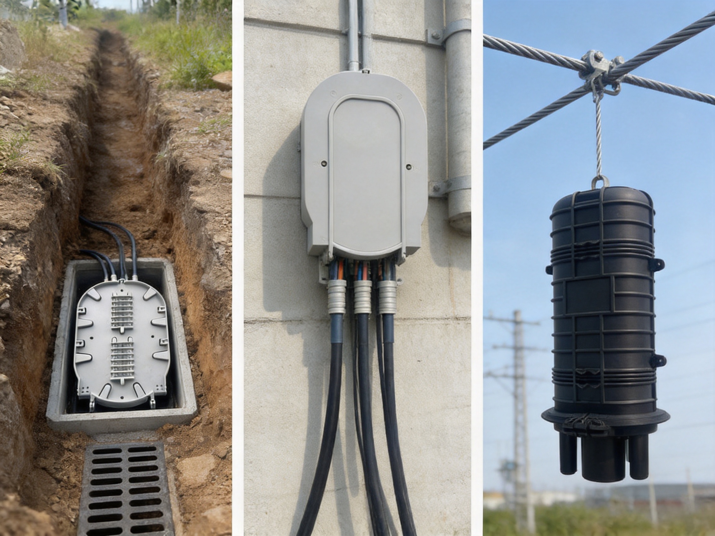
A major advantage of the product is its ability to support multiple installation methods. The same basic closure platform can be used for direct burial, wall mounting, or aerial suspension. This flexibility helps contractors standardize equipment across different sections of a network and reduces the need to manage several unrelated enclosure designs.
7.1 Direct burial installation
For direct burial, the closure is sealed and tested before it is placed into the ground. The installation location should be selected to avoid unnecessary vehicle loading, sharp rocks, unstable soil, and areas with persistent standing water unless the civil design specifically accounts for those conditions. The closure should be surrounded by suitable material that will not damage the shell or cable ports.
Before burial, the technician should inspect the shell, cable entries, internal fiber-routing components, and sealing materials. All cables should be identified, secured, and arranged with appropriate slack. The inflation or sealing verification procedure should be completed according to the manufacturer’s instructions. Burial depth, warning tape, access arrangements, and drainage should follow the network operator’s civil-engineering standards.
7.2 Wall-mounted installation
For wall mounting, the supplied hanging hook or mounting arrangement can be used to secure the closure to a suitable surface. The mounting surface should be strong enough to support the enclosure and cable loads. The closure should not be positioned where building movement, sharp edges, heat sources, or regular impact could compromise the shell or seals.
Wall-mounted closures are common in telecommunications rooms, building entrances, utility corridors, and external service areas. The installation should leave enough working clearance for technicians to open the enclosure and route fibers. Cable loops should be supported so that their weight does not pull against the cable ports.
7.3 Aerial installation
For aerial use, the closure can be suspended from a steel wire using its hanging hook or an approved support arrangement. The support system must carry the mechanical load without transferring excessive tension to the optical fibers. Wind movement, ice loading, vibration, and cable sag should be considered during site design.
The closure should be positioned to minimize water accumulation and to permit safe inspection. Cable entry bends should comply with the cable manufacturer’s minimum bend-radius requirements. All aerial hardware should be corrosion-resistant or appropriately protected for the local environment.
8. Installation Procedure and Best Practices
A successful installation depends on preparation as much as on the closure itself. Before beginning work, the technician should verify the product model, cable types, cable diameters, required fiber capacity, splice-tray arrangement, mounting method, and sealing materials. The work area should be clean and protected from rain, dust, mud, and unnecessary movement.
Step 1: Inspect the closure and accessories
Check the enclosure for cracks, deformation, contamination, missing parts, or damage caused during transportation. Confirm that the basic accessories are available. The listed accessories include cable ties, heat-shrinkable tubes, PVC tubes, heat-shrinkable protection tubes, silver paper, and alcohol paper. The exact quantity and accessory configuration may depend on the project package.
Step 2: Prepare the cables
Identify the incoming, outgoing, and branching cables. Measure the required cable lengths and preserve enough working slack for splicing and future maintenance. Remove the cable jacket carefully without damaging the buffer tubes, fibers, strength members, or water-blocking elements. Clean the cable surface in the sealing area using the appropriate preparation method.
Step 3: Secure the cable structure
Fix the cable strength members and outer cable structures to the designated support points. The purpose is to isolate the delicate fibers from external pulling and twisting forces. Cable ties may be used for organization, but they should not be tightened so strongly that they deform the cable or create localized pressure.
Step 4: Route the fibers
Arrange the fibers in the internal routing system with smooth curves and controlled slack. Avoid crossings that make future identification difficult. Maintain separation between fiber groups and label the cables and splice trays clearly. The minimum bend radius specified by the fiber-cable manufacturer should always be respected.
Step 5: Complete the splices
Perform fusion splicing or the approved connection method in a clean environment. Each splice should be protected with the correct sleeve or protective component. After the splice has cooled and been inspected, place it into the designated tray or holder. Check that no fiber is pinched, sharply bent, or exposed to unnecessary tension.
Step 6: Complete the sealing system
Install the silicone-rubber, heat-shrinkable, and adhesive sealing components according to the approved procedure. Heat-shrinkable materials should be heated evenly with suitable tools. The technician should look for complete recovery, uniform adhesive flow where applicable, and the absence of voids or wrinkles that could create a water path.
Step 7: Close and test the enclosure
Close the enclosure carefully and verify that the body seal is seated correctly. Perform the required inflation, pressure-retention, or leakage test. If the closure does not pass, do not bury or mount it permanently. Recheck cable preparation, sealing surfaces, fasteners, and entry components before repeating the test.
Step 8: Document the installation
Record the closure location, cable identifiers, fiber assignments, splice-tray positions, installation date, sealing test results, and technician details. Good documentation reduces restoration time during future faults and helps operators manage network expansion.
9. Basic Accessories and Their Functions
The supplied accessories are intended to support cable preparation, fiber organization, and sealing. Cable ties assist with controlled arrangement of cables and components. They should be used with moderate tension and positioned where they will not compress fiber tubes.
Heat-shrinkable tubes and heat-shrinkable protection tubes provide insulated, mechanically supported transitions around cable or splice areas. They should be selected and applied according to the relevant cable diameter and heating instructions. PVC tubes can help organize or protect sections of cable and fiber during internal routing.
Silver paper is commonly used as part of preparation or separation procedures in certain installation methods. Alcohol paper is used to clean cable surfaces and working areas before sealing. Clean surfaces are essential because dust, oil, moisture, and residue can prevent a seal from forming correctly.
Accessory compatibility is an important purchasing consideration. The enclosure should be supplied with the correct parts for the intended cable diameters and splice configuration. For projects involving unusual cable constructions, armored cables, ribbon fibers, or very large branch arrangements, the buyer should confirm the accessory list before ordering.
10. Competitive Advantages in Practical Deployment
The most meaningful comparison between splice closures is not simply the number of features listed in a catalog. It is the total value delivered over the network life cycle. Installation time, expansion capability, protection performance, serviceability, and compatibility with several deployment environments all influence the cost and reliability of a project.
10.1 High fiber capacity in a manageable format
A maximum capacity of 288 single fibers gives the product a strong position for high-density access and distribution applications. Some smaller closures may be easier to carry but may require additional enclosures as the network grows. A larger-capacity horizontal closure can consolidate more splices in one protected point, simplify route planning, and reduce the number of external cabinets or underground access locations.
10.2 Reusable design
Reusability is a direct operational advantage. If a closure must be discarded after every maintenance activity, the network operator faces additional material costs, labor, and service interruption. A reusable closure can be reopened, inspected, modified, and resealed when the correct procedure is followed. This feature is particularly valuable in rapidly expanding FTTH networks.
10.3 Multiple mounting options
The ability to support direct burial, wall mounting, and aerial suspension makes the product adaptable to mixed network routes. Competing products may be optimized for only one installation environment or may require separate brackets and accessories for each application. A flexible closure platform can simplify training, inventory management, and project standardization.
10.4 Strong environmental protection
The stated IP68 rating, silicone-rubber sealing, and heat-shrinkable sealing approach are intended to provide robust protection in outdoor conditions. The high-strength PP shell also offers resistance to corrosion, aging, and flame-related risks as described in the product information. These characteristics can be advantageous compared with basic enclosures that offer limited protection or depend on less adaptable sealing systems.
10.5 Mechanical and thermal performance
The listed impact, tension, bending, torsion, pressure, and temperature specifications demonstrate that the product is designed with a broad performance envelope. A closure that is evaluated under several mechanical conditions can provide greater confidence in transportation, installation, and long-term service. The -40°C to +60°C operating range is suitable for many outdoor network regions, although extreme local conditions should be reviewed before deployment.
10.6 Maintenance accessibility
The horizontal layout can make splice access more straightforward than a tightly packed enclosure. Technicians can more easily inspect tray positions, follow fiber routes, and identify cable branches. Maintenance accessibility is a competitive advantage because labor costs and restoration time often exceed the original hardware cost over the life of an optical network.
11. Manufacturing Strengths and Process Control
The performance of a splice closure depends heavily on manufacturing consistency. A design may include appropriate materials and specifications, but variation in shell molding, sealing-component dimensions, accessory quality, or assembly torque can reduce field reliability. The manufacturer’s experience in communication cabinets, electronic communication equipment, and passive optical components is therefore relevant to the product’s development and production capability.
Wanma Technology Co., Ltd. was established in 1997 and has developed experience in communication infrastructure equipment and passive optical products. Its product range serves Ethernet networks, optical communication networks, central equipment rooms, high-speed railway systems, and urban rail transit applications. This application background is valuable because these environments require dependable equipment, consistent supply, and attention to installation constraints.
11.1 Product design and application engineering
A strong manufacturing organization begins with application-oriented design. The closure must be evaluated not only as a molded shell but as a complete system consisting of the enclosure body, cable ports, seals, internal fiber-management components, cable-retention points, hanging hardware, and installation accessories. Design reviews should examine direct burial, wall-mounted, and aerial use cases separately because each creates different mechanical and environmental demands.
Application engineering also supports customization. Network operators may require different cable-entry arrangements, fiber capacities, tray configurations, labels, mounting hardware, or packaging. A manufacturer that develops and markets its own products while also providing integrated solutions for customized products can coordinate these requirements more efficiently than a supplier that only resells standard hardware.
11.2 Material selection and shell production
The specified high-strength PP synthetic plastic must be selected and processed with attention to mechanical strength, dimensional stability, insulation, aging resistance, and environmental exposure. A shell thickness of at least 4 millimeters provides a meaningful structural basis, but molding quality remains essential. Uniform wall thickness, accurate mating surfaces, smooth cable-port geometry, and controlled shrinkage help the closure close correctly and maintain sealing performance.
Manufacturing process control should include incoming material inspection, mold condition checks, dimensional verification, visual inspection, and sampling of mechanical properties. Where flame resistance or special environmental performance is required, the relevant material grade and test evidence should be confirmed for the specific production batch.
11.3 Sealing-component control
Silicone-rubber seals must maintain suitable elasticity and dimensional accuracy. If a seal is too hard, it may not accommodate cable movement or surface variation. If it is too soft or dimensionally inconsistent, it may not provide adequate compression. Heat-shrinkable tubes and adhesive systems must also be matched to the intended cable diameter and installation temperature.
A disciplined production process checks sealing components for surface damage, contamination, dimensional conformity, and correct packaging. Storage conditions matter because heat, sunlight, moisture, or chemical exposure can affect rubber and adhesive materials before installation. Clear batch identification supports traceability when a project requires quality documentation.
11.4 Assembly and inspection
Assembly should follow controlled work instructions covering cable-entry components, internal supports, fasteners, hooks, trays, and seals. Operators should be trained to recognize incorrect seating, missing parts, damaged threads, excessive compression, and other conditions that could affect service performance.
Final inspection can include dimensional checks, visual inspection, accessory verification, closure-operation checks, and sampling-based environmental or mechanical tests. Pressure-retention and sealing tests are especially relevant because they validate the interaction between the shell, body gasket, cable ports, and installation components.
11.5 Testing and documentation
The technical profile includes environmental, mechanical, insulation, compression, and ingress-protection requirements. A reliable manufacturing program should maintain formal test procedures, calibrated equipment, controlled records, and clear acceptance criteria. The source information references YD/T814.1-2013, written as “YD/T814.1-20132” in the supplied text. The applicable standard edition and exact compliance scope should be verified in the current product documentation.
Traceable documentation helps project owners confirm that the supplied product matches the approved design. It also supports troubleshooting if a field issue occurs. Test reports should identify the product model, sample configuration, test conditions, date, equipment, and result. For customized orders, the documentation should clearly distinguish standard specifications from project-specific modifications.
11.6 Supply and partnership capability
Manufacturing strength includes more than factory equipment. A communication project also requires dependable scheduling, packaging, export coordination, technical communication, and after-sales support. The company’s stated sales network covers more than 20 countries and regions, including the United States, Australia, the United Kingdom, Italy, South Africa, and Ghana. International project experience can help a supplier understand varied climate conditions, procurement practices, and network standards.
The company emphasizes reliable quality, timely delivery, and long-term strategic partnerships. These priorities are important for network operators and contractors because splice closures are usually purchased as part of a larger deployment rather than as isolated consumer products. Consistent product supply allows installers to standardize procedures and reduces the risk of mixing incompatible accessories across project phases.
12. Applications in FTTH and FTTB Networks
FTTH networks require extensive branching between feeder cables, distribution cables, and drop-cable systems. A high-capacity closure can be placed at distribution points where multiple fibers must be spliced and protected. The reusable design is useful because subscriber growth can require additional branches after the initial construction phase.
In FTTB networks, the closure may connect an incoming feeder to a building distribution route. Wall mounting can be appropriate in utility rooms, service shafts, or external building areas. The enclosure’s environmental protection is also useful where the building entry point is exposed to humidity, dust, or temperature changes.
For rural broadband, direct burial may provide a practical route where cabinets are limited or where underground access points are preferred. The closure can be installed along feeder routes and documented for future maintenance. In urban areas, the same platform may be wall-mounted or installed in a controlled access location.
13. Applications in Ethernet, Railway, and Transit Infrastructure
Ethernet optical networks often require reliable fiber distribution between buildings, equipment rooms, industrial facilities, and remote communication points. A splice closure protects the passive connection while allowing route flexibility. Its capacity and multiple mounting options can support both new installations and network modernization.
Railway and urban rail transit systems present demanding conditions. Fiber routes may extend along tracks, through tunnels, station facilities, signaling areas, and equipment rooms. Vibration, temperature variation, restricted access, and service-continuity requirements make mechanical protection and clear maintenance organization important. A closure used in these systems must be selected and installed according to the railway operator’s technical and safety requirements.
The manufacturer’s experience serving national high-speed railway and urban rail transit systems provides useful application context. Such experience can support the development of products that account for limited installation space, planned maintenance windows, route documentation, and the need for consistent equipment across multiple infrastructure sites.
14. Applications in Industrial and Outdoor Environments
Industrial facilities may include chemical exposure, dust, vibration, temperature changes, and electromagnetic equipment. A nonmetallic, corrosion-resistant shell can be advantageous in these locations. The closure can protect fiber splices linking production buildings, control rooms, surveillance systems, and data networks.
Outdoor utility routes may be exposed to ultraviolet radiation, rain, wind, snow, soil movement, and accidental contact with tools or equipment. The listed temperature range and impact requirements support consideration for these applications. However, project engineers should evaluate local solar exposure, expected minimum and maximum temperatures, flooding, soil chemistry, and mechanical loading before final selection.
15. Maintenance and Long-Term Reliability
A closure’s stated 25-year working life is an important planning reference, but service life depends on installation quality and environment. Regular inspection should focus on visible deformation, cable movement, mounting stability, water accumulation, damaged seals, and signs of unauthorized opening. Direct-buried closures may require inspection during route maintenance or when an optical fault is detected.
When reopening a closure, technicians should use clean tools and protect the internal splice area from dust and moisture. Existing seals should be inspected rather than automatically reused if they show deformation, cuts, hardening, contamination, or loss of elasticity. Heat-shrinkable and adhesive sealing components may need replacement after opening, depending on the approved maintenance procedure.
Fiber records should be updated whenever a splice is changed. The record should identify the cable, tube, fiber number, splice tray, destination, and date of work. Clear records reduce troubleshooting time and help prevent accidental service interruption during future expansion.
Operators should also avoid placing excessive cable weight on the closure. Cable support should be provided outside the enclosure where required. Bends near cable ports should remain gradual, and the closure should not be used as a substitute for a separate cable-support structure.
16. Procurement Considerations
Before purchasing, the buyer should confirm the actual number and diameter of cable ports. The supplied technical text contains compressed notation such as “Cable port: 103” and “Cable Diameter: φ7-φ204.” These values should be clarified in the formal data sheet, especially if the project involves several cable diameters or different branch configurations.
The buyer should also confirm whether the 288-fiber capacity refers to single fibers, whether ribbon-fiber capacity is supported, which splice trays are included, and whether all required mounting hardware is part of the standard package. The product’s approximate dimensions and weight should be checked against manhole dimensions, cabinet space, wall loading, and aerial support design.
For international projects, procurement teams should request packaging specifications, storage conditions, accessory lists, quality documents, inspection reports, and installation manuals. They should also confirm the applicable standards and whether the supplied product configuration has been tested for the intended cable types and environmental conditions.
17. Why Manufacturing Experience Matters to Buyers
Buyers often compare closures by price, capacity, and protection rating. These factors are important, but the supplier’s manufacturing experience can have an equally significant effect on project risk. A manufacturer established in 1997 and focused on communication cabinets, electronic equipment, and passive optical components is positioned to understand how a closure interacts with the wider network.
Experience across Ethernet, optical communication, central equipment rooms, railway, and transit systems can help the manufacturer identify common field problems. These may include insufficient cable slack, difficult access, incompatible brackets, poor labeling, inadequate sealing preparation, and inconsistent accessory supply. Product improvements based on application feedback can produce more practical equipment than designs developed without field exposure.
Own-brand development can also improve accountability. When the manufacturer controls product design, production, marketing, and technical support, it can coordinate changes more directly. For customized products, this may reduce communication gaps between a project’s engineering requirements and the final factory configuration.
The company’s stated mission emphasizes customer satisfaction, employee fulfillment, and social value. For infrastructure buyers, the practical meaning of this commitment is reflected in product consistency, responsive communication, dependable delivery, and the ability to support long-term relationships rather than only individual transactions.
18. Recommended Quality-Control Checklist
Before shipment, the manufacturer should verify the product model and configuration against the purchase order. The shell should be checked for cracks, deformation, sharp edges, incomplete molding, and contamination. Sealing surfaces should be clean and uniform. Cable ports should match the approved dimensions and accessories.
Internal components should be checked for correct quantity, secure attachment, smooth edges, and compatibility with the specified fiber capacity. Hooks, brackets, cable ties, tubes, protection components, silver paper, and alcohol paper should be counted and packed according to the confirmed accessory list.
Sampling plans should cover mechanical strength, pressure retention, temperature performance, insulation, sealing, and water-ingress protection. Any test performed on a customized configuration should be documented separately from a standard configuration. Packaging should protect the shell and seals against impact, compression, moisture, and excessive heat during transport.
At the project site, the installation team should conduct an incoming inspection before opening the packaging. Any damage or missing accessory should be recorded immediately. This simple step can prevent delays after cables have already been prepared.
19. Sustainability and Life-Cycle Value
Long service life contributes to infrastructure sustainability because equipment that remains reliable for decades does not need frequent replacement. The stated 25-year working life and reusable design can reduce material consumption associated with repeated enclosure replacement. A lightweight PP shell may also reduce transport effort compared with heavier enclosure constructions.
Life-cycle value includes repairability, spare-part availability, compatibility with network expansion, and the ability to maintain existing fiber routes. When a closure can be reopened and expanded, operators may avoid unnecessary excavation, cable replacement, or construction of additional access points.
Responsible disposal should still be considered at the end of service life. Operators should separate plastic, metal hardware, rubber components, adhesive materials, and contaminated items according to local waste-management rules. Manufacturers and project contractors can support sustainability by providing durable packaging, clear material information, and service documentation.
20. Selection Summary
The WM-2001-D10 is best suited to network owners, contractors, and integrators seeking a high-capacity horizontal closure for optical communication infrastructure. Its stated 288-single-fiber capacity supports dense applications. Its silicone-rubber and heat-shrinkable sealing approach addresses environmental protection. Its high-strength PP shell, 4-millimeter minimum thickness, impact and mechanical specifications, and IP68 rating support demanding outdoor use.
The ability to install the closure directly underground, on a wall, or from an aerial steel wire provides practical flexibility. Reusable construction supports network expansion and maintenance. The basic accessory package helps technicians complete cable preparation and sealing work without sourcing every small component separately.
For buyers, the most important next step is to confirm the exact cable-port configuration, fiber-management accessories, current standard compliance, test documentation, and project-specific installation requirements. When these details are correctly matched to the network design, the closure can provide a reliable and serviceable protection point for long-term fiber infrastructure.
21. Questions and Answers
Q1: What type of product is the WM-2001-D10?
It is a horizontal fiber optic splice closure designed to protect optical-fiber splice points and organize cable connections in passive optical communication networks.
Q2: What is its maximum stated fiber capacity?
The stated maximum capacity is 288 single fibers. The exact tray arrangement and practical capacity should be confirmed for the cable and splice configuration used in a specific project.
Q3: Can the closure be used for FTTH and FTTB?
Yes. The product is described as suitable for straight-through, diverging, and connection applications in FTTH, FTTB, and other optical communication passive networks.
Q4: What sealing method does it use?
The product uses silicone rubber as part of its sealing system and also identifies heat-shrinkable sealing and adhesive sealing arrangements. Correct surface preparation and installation are essential to achieving the intended protection.
Q5: Is it suitable for outdoor installation?
Yes. Its stated operating temperature is -40°C to +60°C, and it has a stated IP68 rating. Site conditions, installation quality, cable compatibility, and local environmental requirements should still be evaluated before deployment.
Q6: Can it be buried underground?
Yes. The product description states that it can be directly buried after inflation and sealing. The closure should pass the required sealing test before burial, and civil-engineering requirements for drainage, depth, soil, and access should be followed.
Q7: Can it be mounted on a wall or suspended aerially?
Yes. It can be fixed to a conduit or wall using a hanging hook and can also be suspended from a steel wire for aerial installation, provided the support system is correctly designed.
Q8: What is the shell made from?
The shell is specified as high-strength PP synthetic plastic. The listed shell thickness is at least 4 millimeters. The material is described as offering insulation, heat resistance, corrosion resistance, aging resistance, flame resistance, and long working life.
Q9: Is the closure reusable?
Yes. The product information states that it can be repeatedly reused and that its capacity can be expanded. Any reopening and resealing should follow the approved maintenance procedure, with damaged or contaminated sealing components replaced as necessary.
Q10: Which accessories are included?
The listed basic accessories include cable ties, heat-shrinkable tubes, PVC tubes, heat-shrinkable protection tubes, silver paper, and alcohol paper. Buyers should confirm the exact quantity and configuration for their order.
Q11: What should be confirmed before purchase?
Buyers should confirm the number and diameter of cable ports, cable diameter range, fiber capacity, splice-tray configuration, mounting hardware, applicable standards, test documents, packaging, and compatibility with the project’s cable types.
Q12: Why is supplier manufacturing experience important?
Consistent shell molding, sealing-component quality, assembly, testing, packaging, and technical support all affect field reliability. A supplier experienced in communication cabinets, passive optical components, Ethernet, railway, and transit applications can also provide more relevant application and customization support.
Conclusion
A fiber optic splice closure is a small physical component with a major effect on network continuity. It must protect delicate splices, control cable forces, maintain fiber organization, resist the environment, and remain accessible for future work. The WM-2001-D10 addresses these requirements through a high-capacity horizontal structure, reusable design, silicone-rubber and heat-shrinkable sealing, a high-strength PP shell, broad installation flexibility, and a stated IP68 protection level.
Its competitive value lies in combining capacity, environmental protection, mechanical resistance, maintainability, and deployment versatility in one platform. These features are especially relevant to FTTH, FTTB, Ethernet, railway, urban transit, industrial, and outdoor communication networks.
The product’s performance is supported by the broader capabilities of Wanma Technology Co., Ltd., a communication-equipment manufacturer established in 1997. Its experience with communication cabinets, electronic equipment, passive optical components, Ethernet networks, optical communication systems, railway infrastructure, and urban rail transit provides a strong foundation for product development and application support. Its ability to manufacture its own branded products and provide integrated solutions for customized requirements can help project owners manage complex network deployments.
For the best result, the closure should be selected as part of a complete engineering process. Cable compatibility, sealing preparation, fiber routing, mechanical support, testing, documentation, and future maintenance must all be considered. When these factors are controlled, a high-capacity horizontal splice closure can become a durable foundation for reliable optical connectivity and long-term network modernization.
References
YD/T 814.1-2013, Optical Fiber Cable Connection Hardware and Related Technical Requirements, applicable edition to be confirmed by the project owner and supplier.
International Electrotechnical Commission, IEC 60529, Degrees of Protection Provided by Enclosures.
International Electrotechnical Commission, IEC 61753, Fibre Optic Interconnecting Devices and Passive Components Performance Standards.
International Telecommunication Union, Recommendations for Optical Fibre Cables, Splices, and Passive Optical Network Infrastructure.
ISO 9001, Quality Management Systems Requirements.
Manufacturer technical data for the WM-2001-D10 horizontal fiber optic splice closure.
Manufacturer product and company information concerning communication cabinets, passive optical components, Ethernet networks, railway communication systems, and urban rail transit applications.
Product: WM-2001-D10 Fiber Optic Splice Closure
PREV:Engineering a Reliable FTTH Dome Fiber Optic Splice Closure for Demanding Network Environments
NEXT:Primary and Secondary Integrated Outdoor High-Voltage AC Vacuum Circuit Breaker
NEXT:Primary and Secondary Integrated Outdoor High-Voltage AC Vacuum Circuit Breaker
Interested in cooperation or have questions?
Related products
-
-
Technical data 1. Comply with various technical data of YD/T814.1-20132. Cable port:43. Cable Diameter:φ7-φ204.Max Capacity:12 Fibers 2tray=24 fibers(single)5. Sealing way: silicone rubber6. Dimension...
See Details -
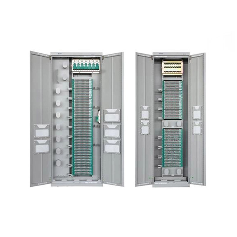
Application ScopeThe GPX129-09T fiber optic distribution frame is used to connect, distribute, and manage fiber optic cables and optical communication equipment. It is suitable for large-capacity fibe...
See Details -
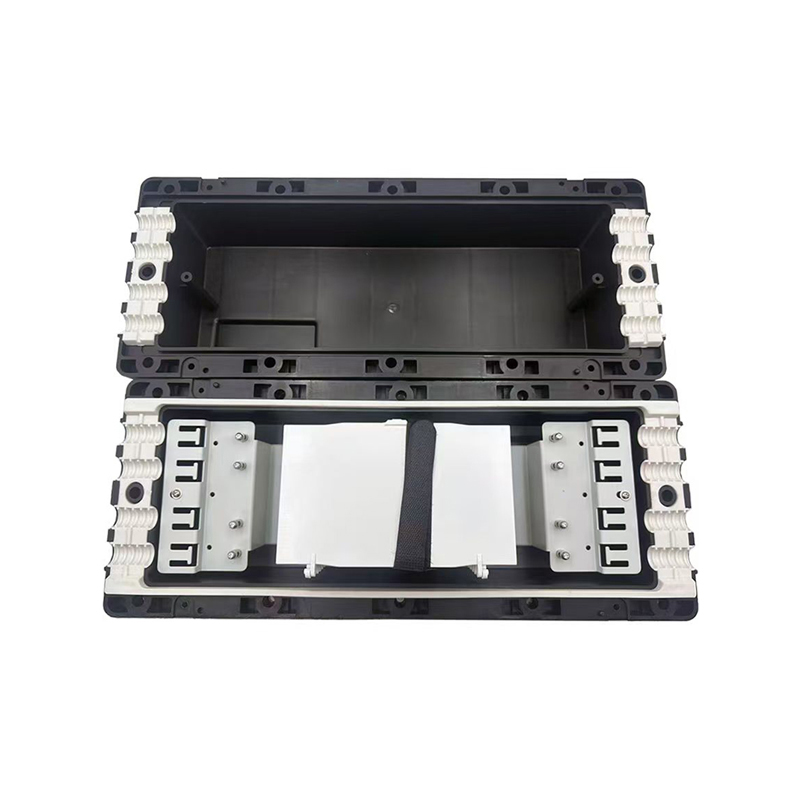
WM-2001-H11 type of It can be used to connect and branch fibers in aerial locations applications. The case body is made from high-intensity engineering plastics and shaped by mould injection under hig...
See Details
Ready to Get started ? Contact Us Now !

Product.
Contact Details.
-
 +86 13958188250
-
 +86 13958188250
-
 [email protected]
-
 AUDIT Email:[email protected]
- Wanma Industrial Park Taihu Yuan Town Lin'an District Hangzhou City China.
QR Code

Copyright © Wanma Technology Co., Ltd. All Rights Reserved.
Privacy
Custom Ethernet Optical Network Railway Transit Equipments Suppliers
