

 English
 Français
 Español
 Português
 عربى






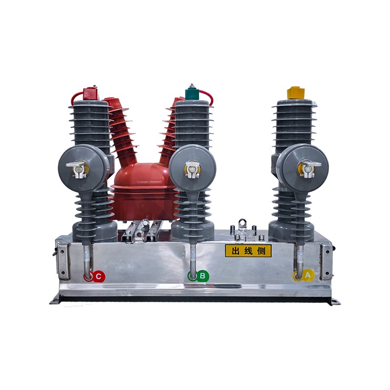
Product Overview: The ZW□-12/T630-25 outdoor high-voltage AC vacuum circuit breaker is a key device designed for 12 kV overhead distribution lines. By deeply integrating the primary switching unit wi...
See DetailsPrimary and Secondary Integrated Outdoor High-Voltage AC Vacuum Circuit Breaker
Content
- 1 1. The Role of Integrated Switching Equipment in Modern Distribution Networks
- 2 2. Product Architecture and Functional Integration
- 3 3. Electrical Performance and Technical Specifications
- 4 4. Vacuum Interruption and Reliable Fault Handling
- 5 5. Outdoor Environmental Adaptability
- 6 6. Solid Insulation and Operational Safety
- 7 7. Flexible Measurement and Protection Configuration
- 8 8. Manufacturing Process and Engineering Strengths
- 9 9. Advantages Compared with Conventional and Competing Solutions
- 10 10. Applications in Distribution and Industrial Networks
- 11 11. Installation, Commissioning, and Maintenance Considerations
- 12 12. Selecting the Appropriate Configuration
- 13 13. Manufacturer Capabilities and Customer Support
- 14 14. Economic and Operational Value
- 15 15. Contribution to Sustainable Distribution Networks
- 16 16. Frequently Asked Questions
- 16.1 Q1. What voltage level is this circuit breaker designed for?
- 16.2 Q2. What does “primary and secondary integrated” mean?
- 16.3 Q3. Can the equipment be operated remotely?
- 16.4 Q4. Does the breaker support automatic reclosing?
- 16.5 Q5. What short-circuit current can it interrupt?
- 16.6 Q6. Is the product suitable for coastal locations?
- 16.7 Q7. Is SF₆ used in the circuit breaker?
- 16.8 Q8. Does the product contain oil?
- 16.9 Q9. What is the protection rating of the enclosure?
- 16.10 Q10. What is the mechanical life?
- 16.11 Q11. Can the current and voltage transformers be customized?
- 16.12 Q12. Can additional sensors be added later?
- 16.13 Q13. What environments are covered by the standard specifications?
- 16.14 Q14. What installation applications are most suitable?
- 16.15 Q15. Why is integrated factory testing important?
- 17 17. Conclusion
- 18 References
- 19 Product: Primary and Secondary Integrated Outdoor High-Voltage AC Vacuum Circuit Breaker
Modern distribution networks require more than a conventional switching device. Utilities and industrial power users increasingly need equipment that can interrupt faults, measure electrical conditions, communicate with control centers, and support automated restoration while remaining reliable in exposed outdoor environments. The primary and secondary integrated outdoor high-voltage AC vacuum circuit breaker is designed to meet these requirements in a single coordinated solution.
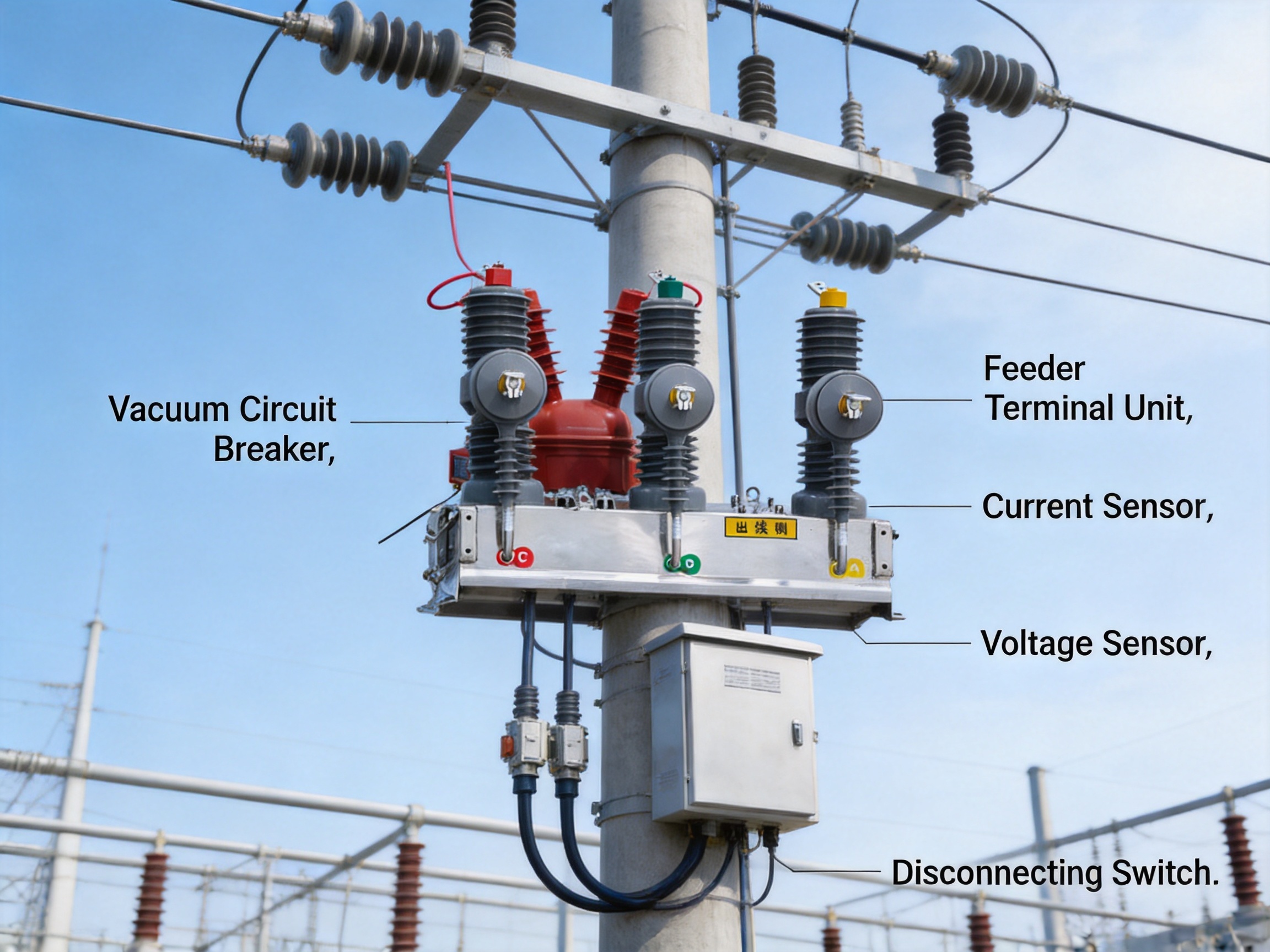
Designed for 12 kV overhead distribution lines, the ZW□-12/T630-25 combines a pole-mounted vacuum circuit breaker with current and voltage sensing, power-taking components, disconnecting functions, and a feeder terminal unit. This integrated architecture supports line sectionalizing, tie connections, customer demarcation, distribution automation, remote monitoring, and rapid fault isolation.
Unlike a basic outdoor circuit breaker that performs only switching and protection functions, this product brings primary power equipment and secondary automation equipment together through standardized connectors and fully insulated cables. The result is a compact and coordinated field device that reduces installation complexity, improves operational visibility, and supports the transition from traditional distribution networks to intelligent, self-monitoring systems.
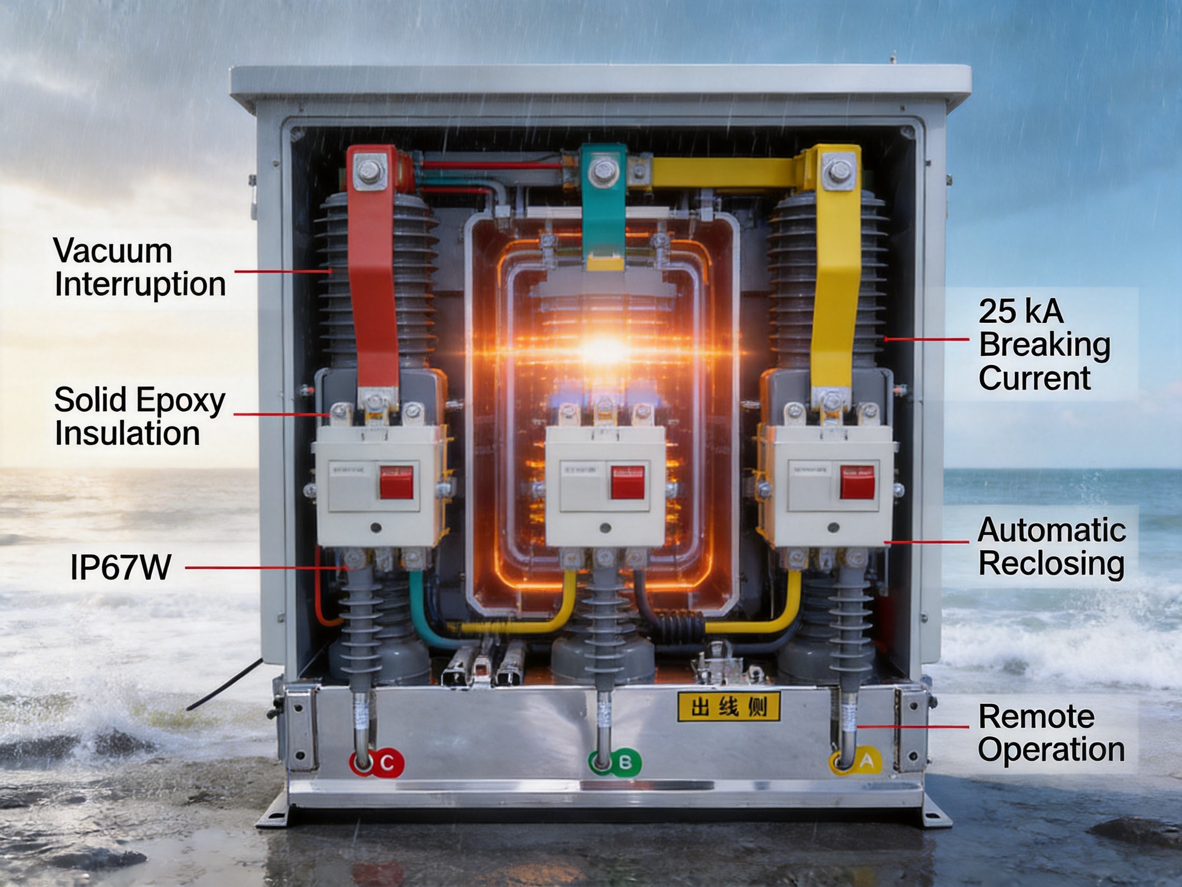
Its design also addresses the practical challenges of outdoor deployment. A corrosion-resistant enclosure, IP67W protection, solid epoxy insulation, vacuum arc interruption, mechanical interlocking, flexible sensing configurations, and operation across a broad environmental range make the equipment suitable for demanding applications. The oil-free and SF₆-free design further supports environmental objectives and simplifies end-of-life handling.
1. The Role of Integrated Switching Equipment in Modern Distribution Networks
Distribution lines are exposed to changing weather, vegetation contact, animal interference, construction activity, lightning, pollution, and equipment aging. When a fault occurs, the network must identify the affected section and disconnect it quickly. If fault isolation is slow or inaccurate, a local problem can become a wider outage affecting customers, industrial facilities, transportation systems, and public infrastructure.
Traditional distribution arrangements often use separate primary switching devices, measurement transformers, control cabinets, communication units, and protection components. Although this approach can be adapted to many projects, it also creates additional cable connections, more installation work, and more potential points of failure. Different devices may be supplied by different manufacturers, with inconsistent interfaces and varying environmental protection levels.
An integrated primary and secondary circuit breaker addresses these limitations by coordinating the major functions in one engineered assembly. The primary side handles current interruption and electrical isolation. The secondary side measures operating conditions, executes protection logic, communicates with the distribution automation system, and supports local or remote control.
This approach is particularly valuable on overhead lines, where space is limited and equipment must be mounted on poles or compact outdoor structures. Reduced wiring, a compact arrangement, and factory-tested interfaces can shorten field installation time and reduce the risk of incorrect connections. In addition, the integrated design makes it easier for operators to obtain accurate information about line status and fault conditions.
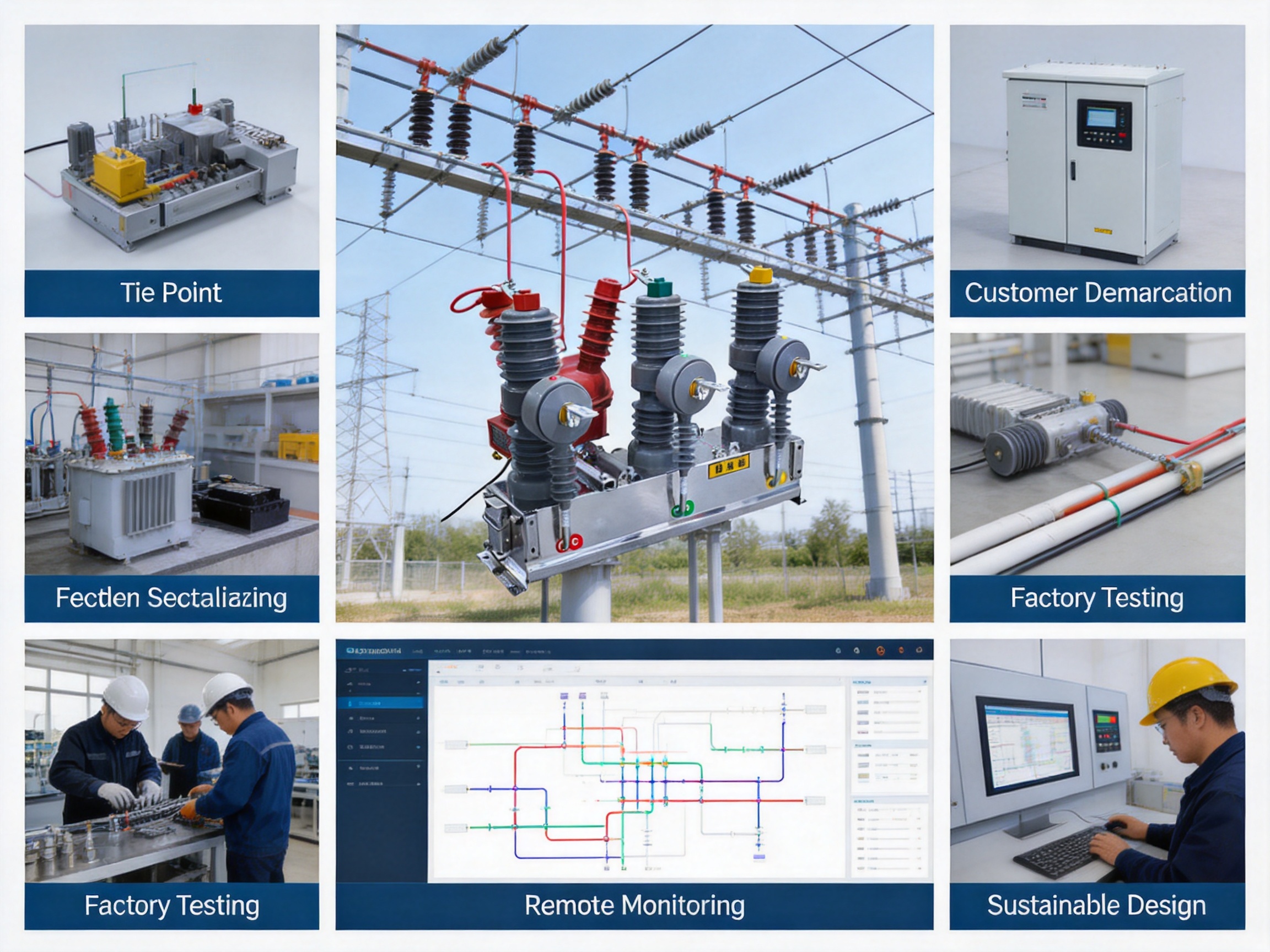
The product is suitable for several important network positions. At a sectionalizing point, it can divide a feeder into manageable sections. At a tie point, it can help connect or transfer power between feeders. At a customer demarcation point, it can distinguish customer-side faults from upstream network faults and disconnect the affected customer branch without unnecessarily interrupting other users.
2. Product Architecture and Functional Integration
2.1 Primary Switching Unit
The primary switching unit is based on a pole-mounted outdoor vacuum circuit breaker. The breaker provides the main current-carrying and current-interrupting path for the 12 kV distribution line. Vacuum interrupters extinguish the arc inside sealed vacuum chambers, avoiding the need for oil or sulfur hexafluoride gas as an interrupting medium.
The primary assembly can be equipped with current transformers, voltage transformers, power-taking capacitors, and single-side or double-side disconnecting switches according to project requirements. These components allow the equipment to perform more than basic open-and-close operations. They provide the electrical signals and isolation capabilities required for protection, measurement, fault analysis, and distribution automation.
The three-phase design generally uses independent poles. This arrangement helps prevent a fault originating in one phase from directly developing into a three-phase short circuit through a common mechanical or insulating structure. Independent phase construction can also simplify inspection, improve phase separation, and support stable insulation performance in outdoor conditions.
2.2 Secondary Feeder Terminal Unit
The feeder terminal unit, or FTU, is supplied as a standard part of the secondary system. It integrates measurement, protection, control, and communication modules in a coordinated terminal enclosure. The FTU can receive data from current and voltage transformers, process electrical information, issue opening or closing commands, and transmit status or fault information to a supervisory system.
For distribution operators, the FTU is the bridge between the field switching device and the automation platform. It enables remote operation and helps the control center understand whether the breaker is open, closed, tripped, or undergoing a protection sequence. Depending on the selected configuration, the terminal can support functions such as fault recording, event reporting, automatic reclosing, remote control, and communication with higher-level systems.
The integration of the FTU with the breaker avoids the need to assemble a separate outdoor control box with extensive site wiring. The primary and secondary components are interconnected through military-grade aviation connectors and fully insulated cables using standardized interfaces. These interfaces are designed to improve connection consistency and reduce exposure of wiring to moisture, mechanical damage, and installation errors.
2.3 Disconnecting and Interlocking Functions
Some applications require a visible isolation point in addition to the circuit breaker. The product can therefore be configured with disconnecting switches on one side or both sides. These switches are intended to provide an appropriate isolation arrangement for maintenance, sectionalizing, and operational management.
Mechanical interlocking is provided to prevent unsafe sequences. For example, the disconnecting switch cannot be opened while the circuit breaker is closed. The breaker must first be opened before the disconnecting switch can be operated. Such interlocking reduces the possibility of operating a disconnecting device under load and helps enforce the intended operating procedure.
The combination of circuit breaking, isolation, sensing, and control in one product gives operators a complete field switching point. It also makes the equipment easier to specify for standardized feeder designs because the principal operating functions are available within one coordinated platform.
Primary and Secondary Integrated Outdoor High-Voltage AC Vacuum Circuit Breaker
3. Electrical Performance and Technical Specifications
The equipment is rated for medium-voltage distribution systems with a nominal rated voltage of 12 kV and a rated current of 630 A. Its rated frequency is 50 Hz, matching common distribution network requirements in many markets. The electrical insulation and short-circuit performance are designed for outdoor service at this voltage level.
| Item | Unit | Specification |
|---|---|---|
| Rated voltage | kV | 12 |
| Rated current | A | 630 |
| Rated frequency | Hz | 50 |
| Rated power-frequency withstand voltage, phase-to-phase and phase-to-ground | kV | 42 |
| Rated power-frequency withstand voltage across the breaker | kV | 48 |
| Rated lightning impulse withstand voltage, phase-to-phase and phase-to-ground | kV | 75 |
| Rated lightning impulse withstand voltage across the breaker | kV | 85 |
| Rated short-time withstand current | kA/s | 25/4 |
| Rated peak withstand current | kA | 63 |
| Rated short-circuit breaking current | kA | 25 |
| Mechanical life | Operations | 12,000 |
| Degree of protection | - | IP67W |
| Loop resistance | μΩ | ≤120 |
| Partial discharge at 1.2Ur | pC | ≤10 |
| Temperature-rise test condition | - | 1.1Ir |
The 25 kA rated short-circuit breaking current provides substantial fault interruption capability for 12 kV distribution applications. The rated peak withstand current is 63 kA, while the short-time withstand rating is 25 kA for four seconds. These ratings help the equipment withstand the thermal and electrodynamic stresses associated with fault events before the protection system completes the interruption sequence.
The insulation system provides a rated power-frequency withstand voltage of 42 kV between phases and from phase to ground, and 48 kV across the open breaker. For lightning impulse conditions, the corresponding ratings are 75 kV and 85 kV. The higher across-breaker values reflect the need to maintain insulation coordination across the open interruption gap as well as through the external insulation system.
A loop resistance of no more than 120 μΩ helps reduce conductive losses and supports stable temperature-rise performance during continuous current operation. The partial-discharge value of no more than 10 pC at 1.2Ur indicates attention to insulation quality and electrical-field control. Low partial discharge is important because repeated discharge activity can gradually damage insulation and reduce long-term reliability.
The mechanical life is specified at 12,000 operations. This rating is valuable for networks that use automatic reclosing, frequent sectionalizing, remote switching, or regular operational reconfiguration. It also provides a useful service-life margin compared with equipment intended only for occasional manual operation.
4. Vacuum Interruption and Reliable Fault Handling
Vacuum interruption is one of the central technical advantages of the product. Inside a vacuum interrupter, the contacts separate in a sealed vacuum environment. The arc is rapidly extinguished as the current approaches zero, and the insulating strength between the contacts recovers quickly after interruption.
Because no oil is used, the equipment avoids risks associated with oil leakage, oil degradation, and oil fire. Because no SF₆ is used, the product does not depend on a greenhouse gas for insulation or arc interruption. This combination of air insulation outside the interrupter and vacuum arc extinguishing inside the interrupter creates a comparatively clean and low-maintenance switching technology for outdoor distribution networks.
The breaker supports both manual and motorized opening and closing. Manual operation provides a local fallback method for commissioning, maintenance, or situations in which auxiliary power or communications are unavailable. Motorized operation enables remote control and automatic sequences through the FTU.
Automatic reclosing is available with adjustable reclosing times and intervals. Many overhead line faults are temporary. Lightning flashovers, momentary contact with branches, wind-driven conductor movement, and transient contamination may disappear after the circuit is opened. An automatic reclosing sequence can restore supply without requiring a field crew to visit the site, provided that the fault has cleared.
If the fault remains, the protection and reclosing logic can prevent repeated energization beyond the configured sequence. This balance between rapid restoration and controlled fault isolation helps improve service continuity while protecting the network and connected equipment.
The integrated terminal can identify and respond to conditions such as single-phase grounding and phase-to-phase short circuits. When the device is installed at a customer demarcation point, it can clear customer-side faults and upload fault information to the control system. This supports more accurate fault responsibility determination and reduces the risk of unnecessary interruption to upstream customers.
Compared with a conventional breaker that only trips locally, an integrated unit can provide a broader operational response. It can detect the event, record relevant electrical information, open the faulted section, report the condition, and participate in restoration or transfer strategies. These functions are especially useful where distribution network operators seek shorter outage durations and more precise service-area management.
5. Outdoor Environmental Adaptability
Outdoor distribution equipment must operate reliably despite rain, condensation, dust, salt, solar radiation, wind, icing, and temperature variation. The product uses a corrosion-resistant enclosure, including S304 stainless-steel materials in applicable structures, to improve resistance to moisture and atmospheric corrosion.
The specified protection level is IP67W. This indicates a highly protected enclosure arrangement for outdoor use, with strong resistance to dust ingress and temporary immersion conditions according to the applicable protection classification. The additional weather-related designation supports the product’s intended exposure to rain and changing outdoor conditions.
| Environmental parameter | Specified value |
|---|---|
| Normal operating temperature | -25 to +50 °C |
| Extreme operating temperature | -40 to +70 °C |
| Relative humidity | 10% to 100% |
| Absolute humidity | 35 g/m³ |
| Atmospheric pressure | 70 to 106 kPa |
| Altitude | Below 3,000 m |
| Solar radiation intensity | 1,000 W/m² |
| Maximum wind speed | 35 m/s |
| Maximum ice coating thickness | 10 mm |
| Pollution level | Level E |
The normal temperature range extends from -25 °C to +50 °C, while the stated extreme range extends from -40 °C to +70 °C. This makes the device suitable for many cold-region and hot-climate applications when the final configuration is selected appropriately. The product overview also identifies suitability for high-salinity and high-altitude environments, subject to project-specific review.
Humidity can be a major cause of insulation deterioration, corrosion, and control-system malfunction. The enclosure, insulated cable arrangement, and sealed connector approach are intended to reduce the effect of moisture and condensation. Nevertheless, installation practices remain important. Cable routing, grounding, mounting orientation, and protection of exposed interfaces should follow the manufacturer’s instructions.
The equipment is specified for altitudes below 3,000 meters. At higher elevations, air density decreases and external insulation performance can be affected. For this reason, users should consult the manufacturer when the actual site exceeds the listed altitude or when other environmental conditions differ materially from the standard operating envelope.
Wind speeds up to 35 m/s and ice coating up to 10 mm are included in the stated environmental conditions. These values are relevant to pole-mounted installations, where mechanical loading can result from wind pressure, conductor tension, and accumulated ice. The final pole, bracket, foundation, and conductor arrangement must be checked as part of the complete installation design.
The stated pollution level is Level E. Severe industrial, coastal, or agricultural pollution may require special insulation coordination, creepage distance assessment, cleaning procedures, or an adapted configuration. Environmental suitability should therefore be verified for each project rather than assumed solely from the general product rating.
6. Solid Insulation and Operational Safety
The poles use epoxy resin solid insulation technology. Solid insulation provides a stable physical support for energized components and can help control the electrical field around the primary circuit. The stated low partial-discharge performance reflects the attention given to insulation design, material selection, molding quality, and production control.
Solid insulation also removes the need for routine handling of liquid insulating media. There is no oil level to inspect and no oil leakage risk during normal service. In combination with vacuum interrupters, the design simplifies the primary insulation and interruption system while maintaining the dielectric performance required for a 12 kV outdoor device.
Safety is supported not only by insulation but also by mechanical design. Complete mechanical interlocking helps prevent improper operation of the disconnecting switches. The operating mechanism can be selected as a spring-operated type or a permanent-magnet type. This gives the system designer flexibility to match the mechanism with the control philosophy, auxiliary power arrangement, operating frequency, and maintenance preference of the network.
A spring mechanism stores mechanical energy for opening and closing operations. It is a familiar technology for many switchgear applications and can provide dependable operation when properly adjusted and maintained. A permanent-magnet mechanism can offer a compact arrangement with fewer mechanical moving parts in the operating system. The availability of both options allows the equipment to serve different project specifications without changing the fundamental primary and secondary integration concept.
Local manual operation is an additional safety and service feature. Field personnel can operate the breaker when remote control is unavailable, subject to the required electrical safety procedures. Clear operating status indication and correct isolation practice remain essential. The circuit breaker should never be treated as a substitute for all required maintenance isolation and grounding procedures.
7. Flexible Measurement and Protection Configuration
Distribution networks differ in fault levels, load profiles, grounding methods, communication architectures, and automation requirements. A fixed sensing arrangement may be adequate for one feeder but unsuitable for another. The product therefore supports flexible selection of current transformers and voltage transformers, including different types and ratios.
Phase current transformers can be combined with zero-sequence current transformers according to the protection scheme. Phase current measurement supports load monitoring, overcurrent protection, and phase fault detection. Zero-sequence measurement assists in identifying ground-fault conditions and can improve the sensitivity of earth-fault protection.
Voltage transformers and power-taking capacitors can support voltage measurement, directional or voltage-dependent protection, and auxiliary power strategies, depending on the selected system design. The final transformer ratio and accuracy requirements should be determined from the network study and the protection coordination plan.
Multiple series of intelligent terminals are available. This enables the product to be adapted to different automation levels, communication requirements, and utility standards. Reserved interfaces for temperature monitoring and partial-discharge monitoring provide a path for future expansion. As sensor technology develops, operators may add condition-monitoring functions without replacing the complete switching platform.
This expandability is an important advantage over a narrowly configured outdoor breaker. A network may initially require only basic remote control and fault indication, but later require more detailed condition data, edge processing, or advanced maintenance analytics. Reserved interfaces and modular secondary functions can help extend the useful value of the installed equipment.
8. Manufacturing Process and Engineering Strengths
8.1 Integrated Product Development
The product is not simply a standard circuit breaker with an external terminal added afterward. Its primary and secondary elements are developed as a coordinated system. Mechanical dimensions, electrical clearances, connector positions, protection logic, control interfaces, and environmental sealing must work together from the beginning of the design process.
This integrated development approach can reduce interface uncertainty between separate suppliers. It also makes it easier to validate the behavior of the breaker, sensors, operating mechanism, FTU, and communication connections as one system. For customers, that means fewer questions about compatibility and a clearer responsibility structure during procurement, commissioning, and service.
8.2 Precision Insulation Manufacturing
Epoxy solid insulation requires controlled material preparation, accurate molding, appropriate curing, and inspection of the finished components. Voids, inclusions, surface defects, or dimensional deviations can affect electric-field distribution and partial-discharge performance. A mature manufacturing process therefore needs control of raw material quality, mold condition, curing parameters, and inspection records.
The target partial-discharge value of no more than 10 pC at 1.2Ur demonstrates the importance of insulation process control. Low partial discharge is not achieved through a single design feature alone. It depends on the interaction of electrical geometry, material quality, cleanliness, molding precision, and final testing.
8.3 Vacuum Interrupter and Mechanism Assembly
Vacuum interrupter assembly requires accurate contact alignment, reliable sealing, and consistent operating travel. The operating mechanism must deliver the required speed and force while maintaining repeatable opening and closing performance over the specified mechanical life. Spring-operated and permanent-magnet mechanisms each require appropriate adjustment, inspection, and functional testing.
Manufacturing control is especially important for an outdoor device because field maintenance opportunities may be limited. Factory assembly should verify mechanical clearances, contact travel, operating time, manual operation, motor operation, auxiliary contacts, and interlocking sequences before shipment.
8.4 Standardized Connector and Cable Integration
The use of military-grade aviation connectors and fully insulated cables reflects a manufacturing philosophy centered on repeatable installation. Connectorized interfaces can reduce the number of field-made terminations and simplify production testing. They also make it easier to identify and replace subassemblies when service is required.
Standardized interfaces must be supported by correct pin assignments, keying, sealing, strain relief, and electrical verification. A connector system is only as reliable as its assembly process. Proper crimping, contact retention, insulation stripping, torque control, and continuity testing are therefore important parts of manufacturing quality.
8.5 Corrosion-Resistant Enclosure Production
Outdoor enclosures require attention to sheet-metal forming, welding, surface treatment, sealing, drainage, and fastener selection. S304 stainless steel can provide strong corrosion resistance in many environments, although highly saline or chemically aggressive locations still require site-specific material and maintenance evaluation.
Consistent enclosure production helps maintain the IP67W protection level. Door alignment, gasket compression, cable-entry sealing, ventilation strategy, and drainage design must be controlled throughout production. The enclosure must protect not only the high-voltage components but also the FTU, communication modules, auxiliary circuits, and connectors.
8.6 Factory Testing and System Verification
Because the product combines primary and secondary functions, testing should cover both individual components and system-level behavior. Electrical routine testing may include insulation checks, contact resistance measurement, dielectric testing, mechanical operation, and control-circuit verification. Secondary testing may include measurement accuracy, protection logic, event recording, communication interfaces, remote commands, and automatic reclosing sequences.
System verification is particularly important for an integrated device. A breaker can pass a mechanical test while a control cable is incorrectly assigned, or an FTU can operate correctly while a sensor ratio is configured incorrectly. Coordinated factory testing helps identify such interface problems before equipment reaches the installation site.
Wanma Technology Co., Ltd. has experience in communication cabinets, communication electronic equipment, passive optical components, and integrated network-related products. This background is relevant to the secondary side of the circuit breaker because modern distribution equipment increasingly depends on reliable communications, cabinet integration, modular electronics, and standardized field interfaces.
9. Advantages Compared with Conventional and Competing Solutions
9.1 Fewer Field Connections
A conventional arrangement may require separate installation of the breaker, transformers, control cabinet, terminal unit, auxiliary power equipment, and communication wiring. Each additional connection increases installation time and creates another point that must be inspected and protected against weather.
The integrated product uses factory-arranged connections between the primary and secondary components. This can reduce field wiring, shorten commissioning work, and improve connection consistency. It is particularly beneficial on overhead line structures where access is difficult and weather conditions may interrupt installation.
9.2 Better Coordination Between Primary and Secondary Functions
Separate devices can perform the required functions, but they must be coordinated through engineering, wiring, settings, and commissioning. An integrated product is designed around the relationship between switching, sensing, protection, and communication. This reduces the risk that one subsystem will not fully support another.
For example, the selected current transformer ratio, FTU measurement configuration, protection threshold, breaker operating mechanism, and communication status indication can be matched as part of the same product solution. This improves design clarity and can simplify responsibility for system performance.
9.3 Improved Outdoor Protection
When a control terminal is installed separately from a breaker, the project must ensure that both enclosures provide sufficient environmental protection and that the connecting cables are properly sealed. The integrated product is designed as a coordinated outdoor assembly with a specified IP67W protection level and corrosion-resistant enclosure materials.
This does not eliminate the need for correct installation, but it reduces the number of exposed interfaces that must be managed in the field. The sealed and standardized cable architecture also helps protect the control and measurement system from moisture-related faults.
9.4 Distribution Automation Readiness
A simple manual breaker may isolate a fault, but it cannot by itself provide complete remote visibility or automated restoration. The integrated FTU supports measurement, protection, communication, and control functions required by automated distribution systems.
With suitable network communication and configuration, the equipment can participate in feeder automation schemes, remote switching, fault location strategies, and customer demarcation applications. This makes it a better fit for utilities seeking to increase automation without installing several separate outdoor devices.
9.5 Environmental Benefits
The oil-free and SF₆-free design avoids the environmental and maintenance considerations associated with oil-filled equipment and greenhouse-gas-based interruption systems. Vacuum interruption provides the required arc-extinguishing function without the use of SF₆.
The integrated and lightweight design can also reduce material use in selected configurations. Less epoxy resin and ferromagnetic material may be used compared with more heavily constructed alternatives, supporting resource efficiency. At the end of service life, an oil-free and SF₆-free product can reduce the environmental burden associated with recovery, containment, and disposal of specialized insulating media.
9.6 Flexible Lifecycle Development
Reserved interfaces for temperature and partial-discharge monitoring provide a foundation for later intelligent upgrades. A utility can begin with the measurement and protection functions required today and add condition-monitoring capabilities as operational needs evolve.
This approach can protect the original investment and reduce the likelihood that the complete field device will need to be replaced when automation requirements become more advanced. It also supports data-driven maintenance by enabling operators to monitor trends rather than relying only on periodic inspection.
10. Applications in Distribution and Industrial Networks
10.1 Feeder Sectionalizing
Feeder sectionalizing divides a long overhead line into multiple protection and operating zones. When a fault occurs, the sectionalizing breaker nearest to the fault can open and isolate the affected section. The remaining sections may continue receiving power from the upstream source or may be restored through an alternate feeder.
The integrated circuit breaker is well suited to this application because it combines local switching capability with fault sensing and communication. Operators can view the status of each section, issue remote commands, and coordinate automatic sequences through the distribution automation system.
10.2 Tie Connections
Tie points connect two feeders or two sections of a distribution network. Under normal conditions, the tie may remain open. During planned maintenance or an outage, it can be closed to transfer power and restore service to customers.
The product’s current and voltage measurement functions help operators confirm electrical conditions before a switching operation. Interlocking and protection functions also support safer operation, although the final tie-switching scheme must include appropriate synchronization, network configuration, and operating procedures.
10.3 Customer Demarcation
At a customer demarcation point, the breaker separates the utility network from a customer’s internal distribution system. If the customer side develops a fault, the device can automatically clear the fault and report information to the utility control center.
This arrangement helps distinguish customer-side incidents from utility-side faults. It can prevent an internal customer fault from unnecessarily tripping a larger upstream area and can provide the customer and utility with clearer information for troubleshooting and restoration.
10.4 Industrial Parks and Remote Facilities
Industrial parks, renewable-energy collection systems, water facilities, communication sites, and remote public infrastructure often require dependable outdoor switching and remote management. A pole-mounted integrated unit can provide a practical solution where a full indoor switchgear room would be costly or difficult to construct.
The compact design and broad environmental capability are useful for remote locations. Motorized operation and communications can reduce the need for field travel, while local manual operation remains available for maintenance and contingency situations.
10.5 Harsh Climate and Coastal Areas
Coastal areas expose equipment to salt-laden air and high humidity. Cold regions may experience freezing temperatures, ice, and condensation. High-altitude locations require careful consideration of insulation performance and atmospheric conditions. The corrosion-resistant enclosure, sealed interfaces, solid insulation, and specified environmental range make the product a candidate for these applications, subject to engineering confirmation.
11. Installation, Commissioning, and Maintenance Considerations
Successful field performance depends on more than the product rating. The pole, mounting bracket, conductor arrangement, grounding system, lightning protection, and communication network must be designed as a complete installation. Mechanical loads from the equipment, conductors, wind, and ice should be evaluated before mounting.
During installation, technicians should inspect the enclosure, insulators, vacuum interrupter assembly, connectors, cable glands, operating mechanism, and disconnecting switches. All transport locks or protective devices should be removed or adjusted according to the installation instructions. The equipment should be installed with adequate clearances from adjacent structures and grounded according to the applicable electrical code and utility standard.
Connector installation deserves special attention. Connectors should be clean, fully engaged, correctly keyed, and protected from excessive cable tension. Cable bends should respect the specified minimum radius. Unused interfaces should remain properly sealed. Incorrect or partially engaged connectors can affect measurement, control, communication, or protection performance.
Commissioning should include manual and motorized opening and closing tests, local and remote control tests, indication verification, interlocking checks, transformer ratio confirmation, protection setting verification, communication testing, and automatic reclosing simulation. If the device is part of a feeder automation scheme, end-to-end tests should confirm that field events are correctly displayed at the control center.
Routine maintenance is simplified by the oil-free and SF₆-free design, but the equipment still requires periodic inspection. Operators should check enclosure condition, corrosion, fasteners, grounding, cable seals, operating mechanism performance, contact resistance, insulation condition, and the status of the communication terminal. The inspection interval should reflect the environment, operating frequency, fault history, and utility maintenance policy.
In polluted or coastal environments, visual inspection and cleaning may be required more frequently. In cold regions, operators should consider ice accumulation and the effect of low temperature on motor operation and auxiliary power. In areas with frequent lightning activity, surge protection and grounding integrity should be reviewed as part of the overall maintenance program.
12. Selecting the Appropriate Configuration
Although the base product is rated at 12 kV and 630 A, the correct configuration depends on the network application. Engineers should first identify whether the equipment will be used for sectionalizing, a tie point, customer demarcation, industrial distribution, or another function.
The required short-circuit level should be confirmed through a system study. The rated short-circuit breaking current is 25 kA, but the actual application must also consider recovery voltage, transient conditions, grounding method, protection coordination, and the number and timing of expected operations.
Current-transformer type and ratio should be selected based on maximum load current, fault current, measurement accuracy, protection sensitivity, and the FTU input range. If earth-fault detection is required, the zero-sequence current transformer arrangement should be specified accordingly.
Voltage transformers or power-taking capacitors should be selected according to the measurement, protection, and auxiliary power requirements. The project should also confirm whether a single-side or double-side disconnecting switch is needed and how the mechanical interlocking should interact with the operating procedure.
The choice between a spring-operated mechanism and a permanent-magnet mechanism should consider the required operating frequency, auxiliary power system, remote-control strategy, maintenance philosophy, and site conditions. Communication requirements should be defined at the procurement stage so that the appropriate intelligent terminal and interface configuration can be supplied.
For high-altitude, severe-pollution, very-low-temperature, or highly saline sites, users should consult the manufacturer before final ordering. Environmental adaptations may affect insulation coordination, materials, heating or anti-condensation measures, transformer selection, and communication equipment configuration.
13. Manufacturer Capabilities and Customer Support
Wanma Technology Co., Ltd. was established in 1997 and has developed experience in communication cabinets, communication electronic equipment, passive optical components, and integrated network solutions. This product background provides a useful foundation for developing equipment in which electrical switching and intelligent communications must operate together.
The company develops, manufactures, and markets its own branded products while also providing integrated solutions for customized requirements. This combination can benefit customers whose projects require more than a standard catalog device. Customization may involve enclosure arrangements, sensing configurations, communication interfaces, intelligent terminals, mounting solutions, or application-specific protection functions.
Experience with communication cabinets and electronic equipment is especially relevant to the secondary portion of the circuit breaker. Outdoor automation products must protect sensitive electronics while maintaining reliable signal paths, serviceable layouts, and consistent interfaces. Manufacturing experience in these areas can support better integration between the FTU, connectors, cables, and enclosure.
The company serves customers in more than 20 countries and regions, including markets in North America, Australia, the United Kingdom, Italy, South Africa, and Ghana. An international customer base requires attention to different environmental conditions, installation practices, utility requirements, documentation expectations, and logistics arrangements.
Wanma Technology emphasizes reliable product quality, timely delivery, and long-term strategic partnerships. For distribution equipment, these factors are important because the product may become part of a utility’s standardized equipment family. Consistent supply, technical communication, customization support, and after-sales service can be as important as the initial equipment price.
The company’s broader mission is connected with customer satisfaction, employee fulfillment, and social value. In the context of this circuit breaker, that mission is reflected in a product concept that combines network reliability, intelligent operation, environmental responsibility, and practical field installation.
14. Economic and Operational Value
The purchase price of a switching device is only one part of its lifecycle cost. Installation labor, commissioning time, communication integration, inspection requirements, outage duration, emergency maintenance, and eventual disposal can have a significant effect on the total cost of ownership.
By integrating the FTU and primary switching components, the product can reduce the number of separate field assemblies. Less site wiring may mean fewer installation hours and fewer opportunities for incorrect termination. Factory coordination can also reduce commissioning delays caused by incompatibility between separately sourced equipment.
Remote operation and fault reporting can reduce the number of truck rolls required for routine switching and initial fault assessment. Faster isolation and restoration can reduce the operational impact of outages, particularly for commercial customers, industrial users, and essential services.
The mechanical life of 12,000 operations supports applications that involve more frequent switching than ordinary manual disconnecting equipment. Vacuum interruption and the absence of oil can reduce certain routine maintenance tasks, while the SF₆-free design avoids gas management requirements.
These advantages should be evaluated through a project-specific lifecycle analysis. Savings will depend on the network automation architecture, communications availability, labor costs, fault frequency, environmental severity, and local maintenance practices. Nevertheless, the integrated design offers several routes to improved long-term value beyond the initial equipment specification.
15. Contribution to Sustainable Distribution Networks
Electricity networks are being modernized not only to improve reliability but also to reduce their environmental footprint. Equipment selection affects material consumption, greenhouse-gas use, leakage risk, maintenance resources, and end-of-life processing.
The product uses vacuum arc-extinguishing technology and does not use SF₆ or other greenhouse gases for insulation or interruption. Its oil-free construction also avoids oil containment and leakage concerns. These characteristics support cleaner equipment deployment in distribution networks.
The lightweight and integrated design can reduce the amount of material needed for selected structures. Reduced use of epoxy resin and ferromagnetic materials is identified as part of the product’s environmental design approach. Lower mass can also simplify transportation and pole-mounted installation, although the actual environmental benefit depends on the final configuration and logistics route.
At decommissioning, the absence of oil and SF₆ can simplify environmental management. Components still require responsible separation and disposal, and electronic modules, metals, epoxy materials, and vacuum interrupters should be handled according to applicable regulations. Even so, the design can reduce the specialized disposal pressure associated with oil-filled or SF₆-filled equipment.
16. Frequently Asked Questions
Q1. What voltage level is this circuit breaker designed for?
The product is designed for 12 kV outdoor AC distribution systems. Its rated current is 630 A, and its rated frequency is 50 Hz.
Q2. What does “primary and secondary integrated” mean?
It means that the primary switching equipment and the secondary measurement, protection, control, and communication equipment are supplied as one coordinated product. The primary side includes the vacuum circuit breaker and optional sensing and disconnecting components, while the secondary side includes the FTU.
Q3. Can the equipment be operated remotely?
Yes. The motorized operating mechanism and FTU support remote opening and closing when the appropriate auxiliary power and communication systems are provided. Local manual operation is also supported.
Q4. Does the breaker support automatic reclosing?
Yes. Automatic reclosing functions are available, with adjustable reclosing times and intervals. The final sequence should be configured according to the feeder protection and automation scheme.
Q5. What short-circuit current can it interrupt?
The listed rated short-circuit breaking current is 25 kA. The equipment also has a rated short-time withstand current of 25 kA for four seconds and a rated peak withstand current of 63 kA.
Q6. Is the product suitable for coastal locations?
The corrosion-resistant enclosure and sealed outdoor design support use in demanding environments, including high-salinity areas. However, the exact coastal conditions should be reviewed before ordering because salt concentration, pollution, wind, and maintenance practices vary by site.
Q7. Is SF₆ used in the circuit breaker?
No. The product uses air insulation and vacuum arc-extinguishing technology. It does not use SF₆ or other greenhouse gases as the interruption medium.
Q8. Does the product contain oil?
No. It uses an oil-free design, which avoids oil leakage and oil maintenance requirements associated with oil-filled switching equipment.
Q9. What is the protection rating of the enclosure?
The listed degree of protection is IP67W. This supports outdoor deployment when the equipment is installed and maintained in accordance with the manufacturer’s instructions.
Q10. What is the mechanical life?
The specified mechanical life is 12,000 operations. Actual service life also depends on operating conditions, maintenance, environmental exposure, and the frequency of fault interruption.
Q11. Can the current and voltage transformers be customized?
The type and ratio of current and voltage transformers can be flexibly configured. Phase current transformers and zero-sequence current transformers can also be combined according to the protection and measurement requirements.
Q12. Can additional sensors be added later?
Reserved interfaces are provided for expansion functions such as temperature and partial-discharge monitoring. The available expansion options should be confirmed during technical clarification and ordering.
Q13. What environments are covered by the standard specifications?
The normal temperature range is -25 to +50 °C, with an extreme range of -40 to +70 °C. The listed altitude is below 3,000 meters, with maximum wind speed of 35 m/s, maximum ice coating thickness of 10 mm, and pollution level E. Sites outside these conditions should be reviewed with the manufacturer.
Q14. What installation applications are most suitable?
The product is suitable for overhead line sectionalizing, feeder tie connections, customer demarcation points, distribution automation systems, industrial parks, remote facilities, and other outdoor 12 kV switching locations.
Q15. Why is integrated factory testing important?
Because the product combines switching, sensing, control, protection, and communication, all functions must work together. Factory testing can verify mechanical operation, insulation, contact resistance, transformer connections, interlocking, protection logic, remote control, and communication before delivery.
17. Conclusion
The primary and secondary integrated outdoor high-voltage AC vacuum circuit breaker is designed for distribution networks that require reliable switching and intelligent field control in one outdoor platform. Its 12 kV, 630 A rating, 25 kA short-circuit breaking capability, 12,000-operation mechanical life, and strong insulation performance provide a solid foundation for medium-voltage distribution applications.
Its main advantage over a conventional standalone breaker is functional integration. The product combines vacuum interruption, current and voltage measurement, optional disconnecting switches, an FTU, motorized operation, automatic reclosing, fault reporting, and communication interfaces. This can reduce field wiring, improve commissioning consistency, and support distribution automation.
The product also addresses demanding outdoor conditions through corrosion-resistant materials, IP67W protection, solid epoxy insulation, sealed connectors, and a broad operating temperature range. The oil-free and SF₆-free design supports environmental goals while reducing certain maintenance and end-of-life concerns.
Wanma Technology’s experience in communication cabinets, electronic equipment, passive optical components, and integrated network solutions supports the product’s emphasis on reliable secondary systems and standardized interfaces. Its manufacturing approach brings together insulation production, vacuum switching technology, mechanism assembly, enclosure fabrication, connector integration, and system testing.
For utilities, industrial users, and infrastructure operators seeking more automated and maintainable outdoor distribution equipment, this integrated circuit breaker offers a practical combination of electrical performance, environmental adaptability, operational safety, configuration flexibility, and future expansion capability.
References
1. Product technical specification sheet for the ZW□-12/T630-25 outdoor high-voltage AC vacuum circuit breaker.
2. Manufacturer-provided product overview and application information for primary and secondary integrated distribution equipment.
3. IEC 62271 series, High-voltage switchgear and controlgear.
4. IEC 60529, Degrees of protection provided by enclosures.
5. IEC 62271-100, High-voltage alternating-current circuit-breakers.
6. General principles of distribution automation, feeder protection, and automatic reclosing engineering.
7. General practices for outdoor switchgear insulation coordination, environmental qualification, and maintenance planning.
Product: Primary and Secondary Integrated Outdoor High-Voltage AC Vacuum Circuit Breaker
PREV:Engineering Guide to High-Capacity Horizontal Fiber Optic Splice Closures
NEXT:WM-2001-H10 Fiber Optic Splice Closure: Reliable Protection and Flexible Distribution for Modern Optical Networks
NEXT:WM-2001-H10 Fiber Optic Splice Closure: Reliable Protection and Flexible Distribution for Modern Optical Networks
Interested in cooperation or have questions?
Related products
-
-
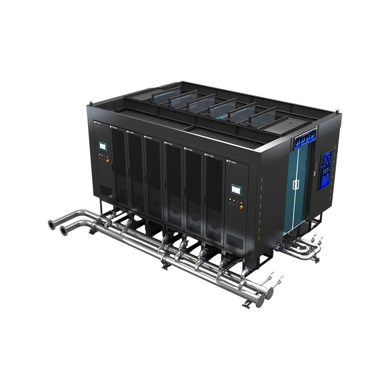
Product OverviewWM-HCM Air-Liquid Hybrid Micro-Module is an integrated data center solution designed for ultra-high-density computing applications. It adopts a dual-row, back-to-back layout and integr...
See Details -
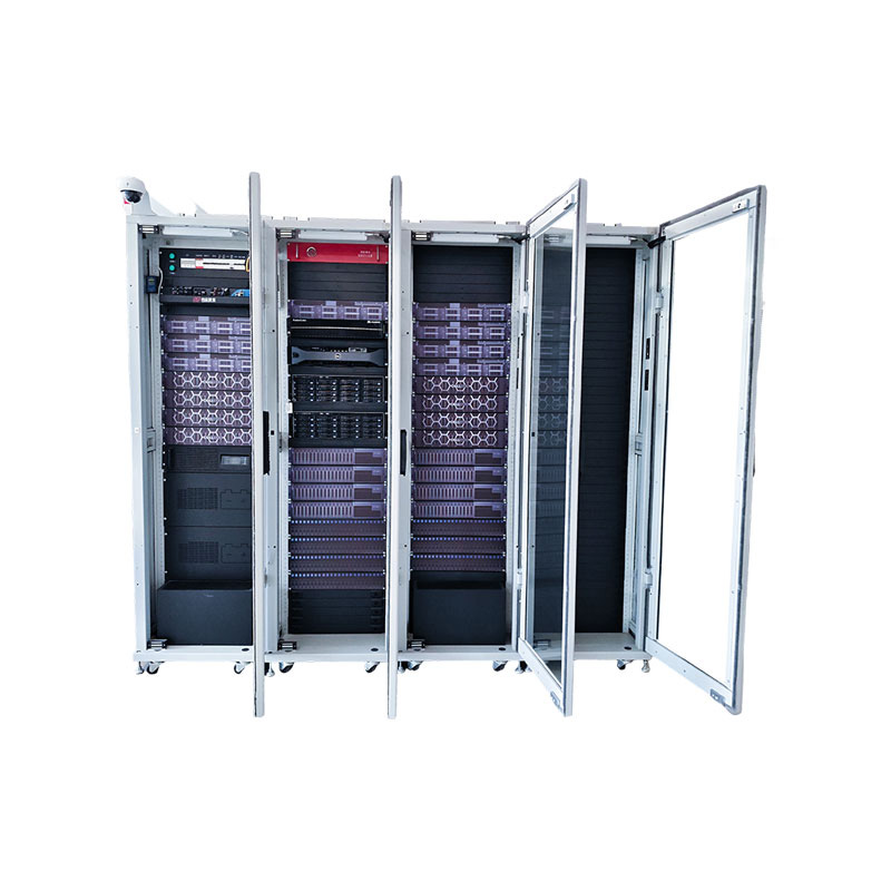
Product DefinitionThe Integrated Air-Cooled Cabinet adopts an "all-in-rack" design, deeply integrating cabinet structure, cooling, power distribution, cabling, and intelligent management subsystems to...
See Details -
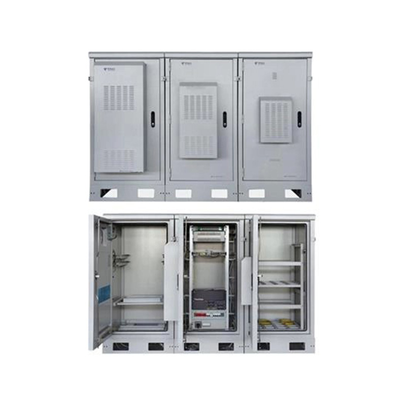
Application ScopeThis product is used in wireless network coverage systems, providing a safe and stable physical working environment and comprehensive security protection for workstations at wireless ...
See Details
Ready to Get started ? Contact Us Now !

Product.
Contact Details.
-
 +86 13958188250
-
 +86 13958188250
-
 [email protected]
-
 AUDIT Email:[email protected]
- Wanma Industrial Park Taihu Yuan Town Lin'an District Hangzhou City China.
QR Code

Copyright © Wanma Technology Co., Ltd. All Rights Reserved.
Privacy
Custom Ethernet Optical Network Railway Transit Equipments Suppliers
