

 English
 Français
 Español
 Português
 عربى





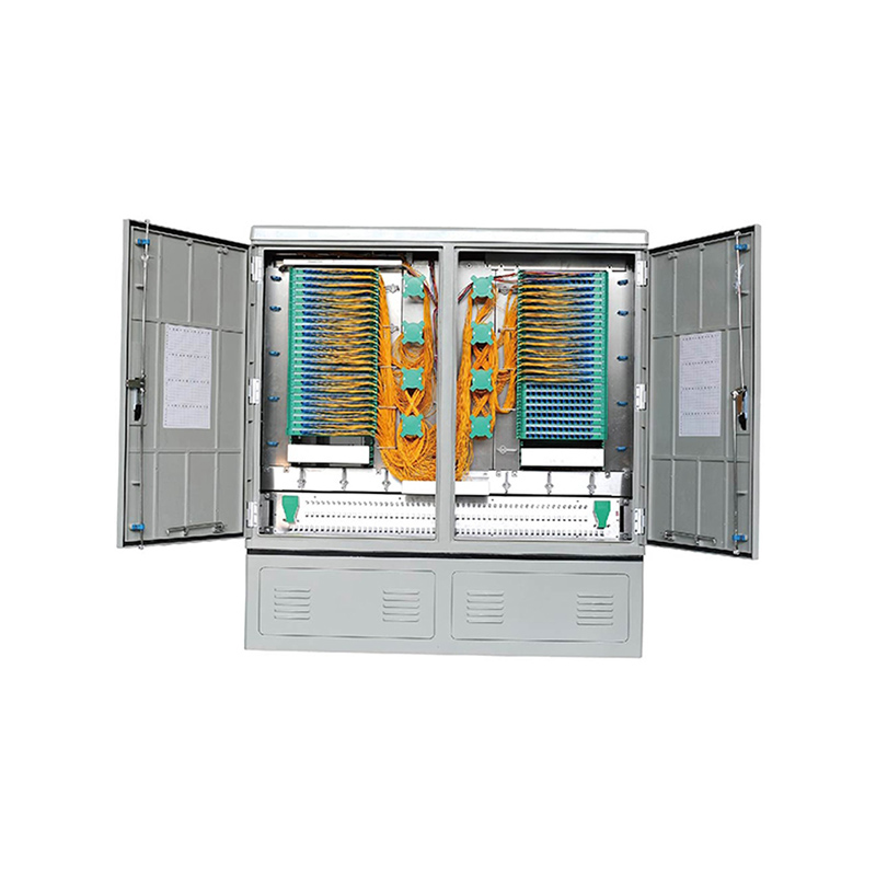
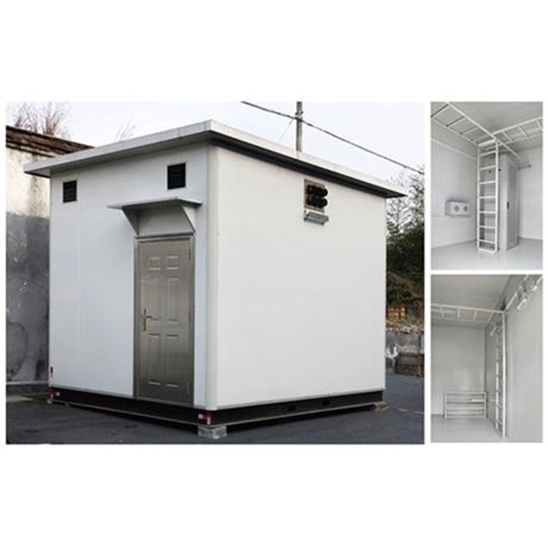
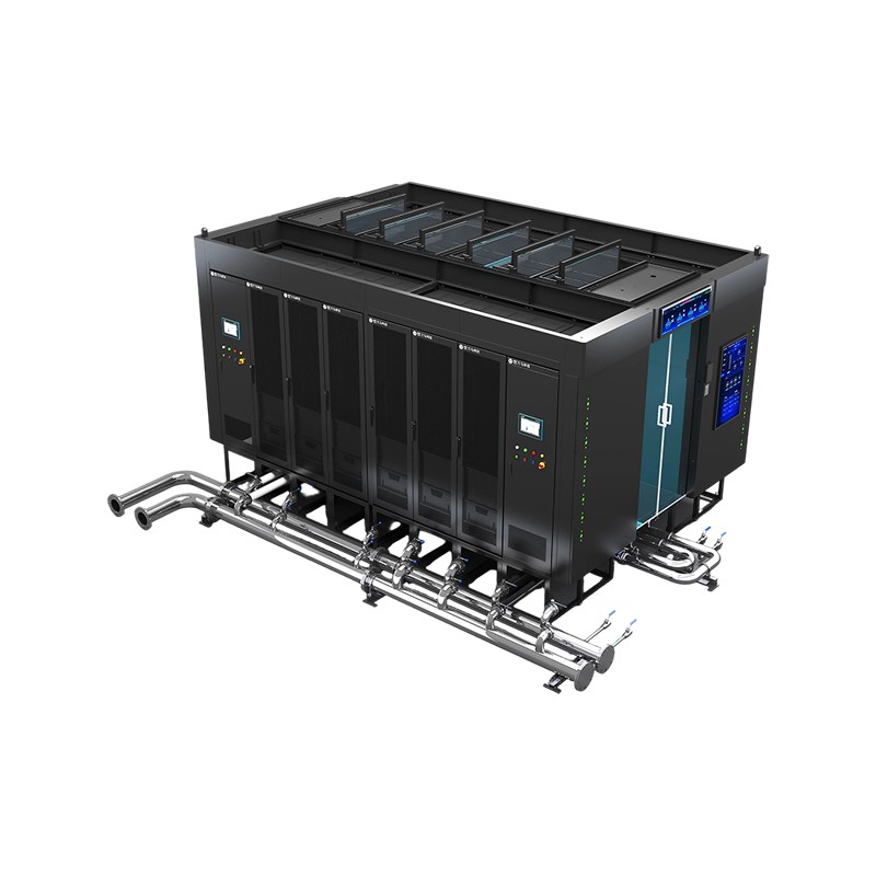

Application Used in independent fiber patching areas of newly built communication equipment rooms and central equipment rooms. After cable removal, the original main distribution frame is dismantled, ...
See DetailsFiber Solution Optical Main Distribution Frame for High-Capacity Communication Rooms
Content
- 1 1. The Role of an Optical Main Distribution Frame
- 2 2. Product Architecture and Functional Layout
- 3 3. Key Advantages of the GPX129-OMDF Design
- 4 4. Capacity Options and Configuration Flexibility
- 5 5. Advantages Compared with Conventional or Less-Structured Alternatives
- 6 6. Manufacturing and Engineering Strengths
- 7 7. Manufacturing Process from Design to Delivery
- 8 8. Installation and Operation Considerations
- 9 9. Applications Across Communication Networks
- 10 10. Maintenance, Expansion, and Lifecycle Value
- 11 11. Project Selection Guide
- 12 12. Frequently Asked Questions
- 12.1 12.1 What is the primary application of the GPX129-OMDF?
- 12.2 12.2 What management method does the system use?
- 12.3 12.3 Why is the frame divided into three functional areas?
- 12.4 12.4 What is the advantage of the open aluminum alloy structure?
- 12.5 12.5 Are the external and internal line sides designed differently?
- 12.6 12.6 How are patch cords managed?
- 12.7 12.7 Does the listed capacity include testing ports?
- 12.8 12.8 Can the frame be used for network expansion?
- 12.9 12.9 Is the product suitable for railway communication networks?
- 12.10 12.10 Can customized configurations be requested?
- 12.11 12.11 What should be confirmed before ordering?
- 12.12 12.12 How does the product support maintenance?
- 13 13. Why Manufacturer Capability Matters
- 14 14. Conclusion
- 15 References
- 16 Product: Fiber Solution-Optical Main Distribution Frame---GPX129-OMDF
Modern communication networks depend on orderly, accessible, and scalable fiber infrastructure. As optical fiber deployment expands across data centers, telecommunications hubs, railway systems, urban rail transit networks, enterprise campuses, and 5G access environments, the main distribution frame becomes more than a passive mounting structure. It serves as the physical management center where outside-plant cables, internal equipment connections, splicing operations, testing activities, and fiber jumper routing must work together safely and efficiently.
The GPX129-OMDF optical main distribution frame is designed for this demanding operating environment. It provides a structured platform for independent fiber patching areas in newly built communication equipment rooms and central equipment rooms. It can also support modernization projects in which an existing cable measuring room is converted into an optical fiber measuring room after the removal and dismantling of a conventional main distribution frame.
With an open aluminum alloy frame, clearly separated functional zones, integrated trays, organized jumper management, and scalable capacity options, the system applies a traditional main distribution frame management model to optical fiber infrastructure. This approach combines familiar operational practices with the high-density, low-loss, and high-flexibility requirements of modern optical networks.
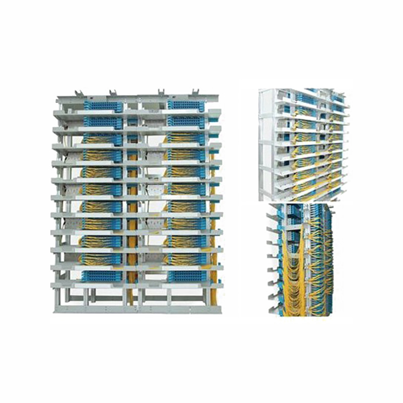
Fiber Solution-Optical Main Distribution Frame---GPX129-OMDF
1. The Role of an Optical Main Distribution Frame
An optical main distribution frame, commonly called an OMDF, is a central physical interface between incoming optical cables and the equipment or distribution systems connected to them. It provides a controlled environment for cable termination, fiber splicing, patching, testing, identification, and rearrangement.
Without a properly designed OMDF, a communication room can quickly become difficult to maintain. Fiber cables may cross one another, patch cords may be routed under excessive tension, spare capacity may be difficult to identify, and troubleshooting may require unnecessary service interruptions. A well-designed frame addresses these risks by giving each activity a defined location and by keeping the cable management path visible and accessible.
The GPX129-OMDF is intended for independent fiber patching areas in new communication equipment rooms and central equipment rooms. Its use is particularly relevant where a network operator wants to replace a conventional copper-oriented distribution arrangement with an optical fiber management system while retaining an organized main distribution frame method.
The frame is also suitable for conversion projects. After old cables are removed and the original main distribution frame is dismantled, a former cable measuring room can be adapted into an optical fiber measuring room. The optical main distribution frame then becomes the central point for optical cable termination, fiber distribution, testing, and connection management.
This type of infrastructure supports both new construction and network modernization. It allows operators to improve the physical organization of their optical network without requiring an entirely new operating philosophy. Maintenance personnel can continue to work with the familiar concepts of external lines, internal lines, testing ports, distribution positions, and jumper connections.
2. Product Architecture and Functional Layout
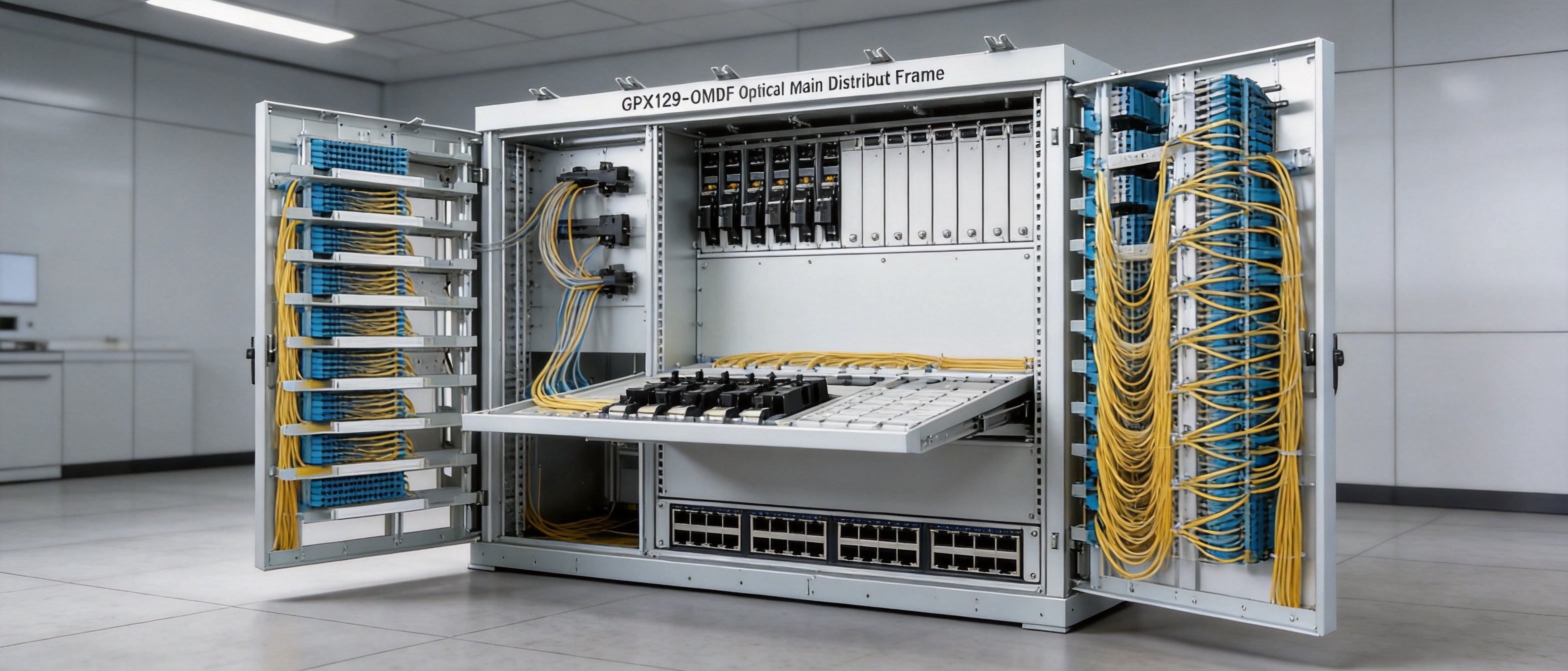
The GPX129-OMDF uses an open aluminum alloy frame structure. The open design allows technicians to approach the relevant working area directly, which is valuable during patching, testing, expansion, and inspection. Instead of enclosing the optical management system in a deep cabinet with limited visibility, the frame exposes the working zones and supports straightforward access.
The frame is divided into three principal functional areas:
2.1 Cable Stripping Area
The cable stripping area is used for the controlled preparation of incoming optical cables. Cable jackets and protective layers can be removed in a designated space before individual fibers are routed toward the splicing and distribution area. Separating this activity from patching and jumper management helps limit accidental interference with already connected fibers.
A dedicated stripping area also supports more consistent installation practices. Technicians can plan the cable entry path, provide suitable slack, secure the cable, and guide the exposed fibers toward the next processing stage. This is important because improper preparation at the cable entry point can create bending stress, mechanical damage, or difficulty during later maintenance.
2.2 Splicing and Distribution Area
The splicing and distribution area is the technical center of the frame. It provides a location for connecting incoming fiber cores, arranging spliced fibers, installing distribution modules, and managing the relationship between external line fibers and internal equipment-side fibers.
By locating splicing and distribution functions in a defined area, the design helps separate permanent or semi-permanent fiber connections from frequently changed jumper connections. This distinction improves clarity. A technician can identify whether a fault is associated with the incoming cable, the splice, the distribution module, the test interface, or the jumper path.
2.3 Jumper Fiber Area
The jumper fiber area is intended for the routing and storage of patch cords. Patch cords are hung on both sides of the frame to prevent interweaving and to maintain an orderly routing arrangement. This feature is especially valuable in high-capacity installations where a large number of jumpers must be connected, disconnected, or rearranged over the operating life of the facility.
Separating jumper fibers from the cable stripping and splicing areas also reduces the possibility that active patch cords will obstruct access to permanent cable connections. It supports a cleaner working environment and makes routine tracing more efficient.
The three-zone layout gives each process a defined operational boundary. Cable preparation, splicing and distribution, and jumper management can be conducted independently while remaining part of one integrated optical infrastructure platform.
3. Key Advantages of the GPX129-OMDF Design
3.1 Open Aluminum Alloy Frame Construction
The open aluminum alloy construction is one of the product’s most important design advantages. Aluminum alloy provides a practical combination of structural strength, relatively low weight, corrosion resistance, and suitability for modular equipment-room construction.
For installation teams, a lighter frame can simplify positioning, handling, and assembly compared with heavier conventional structures. For operators, the open format improves visibility and access. Technicians can inspect cable paths, identify patching positions, and reach the required working zone without removing multiple enclosure panels.
The open structure also supports future expansion. When a network grows, additional modules or working positions can be installed with less disruption than would typically be associated with a closed, highly integrated cabinet. Expansion work can be carried out with a clearer view of the existing arrangement, reducing the risk of disturbing active connections.
3.2 Independent Functional Operation
The three functional areas support separate and independent operation. This means that cable preparation, splicing and distribution, and jumper management do not need to be treated as one crowded workspace.
This separation improves maintenance efficiency in several ways. A technician working on jumper connections can avoid unnecessary contact with the cable entry and splice areas. A technician conducting cable preparation can work without moving large groups of patch cords. A testing team can identify and access relevant ports more systematically.
Independent operation is also useful during staged installation. Incoming cables may be prepared before all equipment-side jumpers are installed. Distribution modules can be populated in phases. Additional capacity can be introduced without completely reorganizing the frame.
3.3 Integrated Tray Design
Both the external line side and the equipment side adopt the same integrated tray design. This gives the two sides a common structural approach and supports module interchangeability.
Interchangeability is valuable for network operators that maintain multiple rooms or sites. A consistent tray design can simplify spare-parts planning, technician training, installation procedures, and replacement activities. If the same type of module can be used in different positions, the number of specialized components required for maintenance may be reduced.
The integrated tray concept also improves adaptability. Network requirements may change over time as transmission equipment is upgraded, connection patterns are revised, or new service areas are added. A modular tray structure gives the operator more flexibility than a fixed arrangement designed for only one original configuration.
3.4 Organized Jumper Routing
Patch cords are hung on both sides of the frame to prevent interweaving. This is a practical feature with a direct effect on long-term maintenance.
Interwoven patch cords make it difficult to trace a connection, identify a spare path, or remove one jumper without disturbing another. They can also create excessive bending, accidental pulling, and unclear routing. By providing organized hanging and routing positions, the GPX129-OMDF supports cleaner cable paths and more reliable access.
Orderly routing is particularly important in high-density rooms. As the number of connected fibers increases, the difference between a managed frame and an unmanaged frame becomes increasingly significant. A structured path can reduce the time required for identification, fault isolation, service rearrangement, and capacity expansion.
3.5 Software-Assisted Jumper Length Planning
The equipped software system can automatically calculate and recommend fiber jumper lengths. This capability helps address a common practical challenge in large optical installations: selecting suitable jumper lengths for different frame positions and connection paths.
Overly long jumpers may create loops, congestion, and unnecessary storage requirements. Overly short jumpers may create tension or fail to reach the required port. Automatic calculation and recommendation can provide a more consistent planning method and reduce dependence on manual estimation.
Software-assisted planning also supports better material preparation. Before installation, the operator can determine the expected jumper requirements and arrange the appropriate lengths. This may reduce installation delays, limit surplus cable, and improve the appearance and maintainability of the completed system.
4. Capacity Options and Configuration Flexibility
The GPX129-OMDF is available in double-sided and single-sided OMDF configurations. Different capacity options are provided to support communication rooms with varying fiber counts and expansion requirements.
| Configuration | Type | Dimensions | External Line Capacity | Internal Line Capacity | Notes |
|---|---|---|---|---|---|
| Double-sided OMDF | GPX129-OMDF-SZ20 | 2000 × 840 × 650 mm | 672 cores | 504 cores | External and internal line capacities exclude testing ports. |
| Double-sided OMDF | GPX129-OMDF-SZ22 | 2000 × 840 × 650 mm | 768 cores | 576 cores | External and internal line capacities exclude testing ports. |
| Double-sided OMDF | GPX129-OMDF-SZ26 | 2000 × 840 × 650 mm | 960 cores | 720 cores | External and internal line capacities exclude testing ports. |
| Single-sided OMDF | GPX129-OMDF-SZ20 | 2000 × 1680 × 520 mm | 720 cores | 720 cores | Configuration should be confirmed during project ordering. |
| Single-sided OMDF | GPX129-OMDF-SZ22 | 2000 × 1680 × 520 mm | 792 cores | 792 cores | Configuration should be confirmed during project ordering. |
| Single-sided OMDF | GPX129-OMDF-SZ26 | 2000 × 1680 × 520 mm | 836 cores | 936 cores | Configuration should be confirmed during project ordering. |
The listed capacity options enable project planners to match the frame to the expected number of external and internal fiber cores. Selecting a suitable configuration requires consideration of current demand, planned network growth, room dimensions, access paths, maintenance clearance, and the number of testing ports required.
Double-sided designs can be useful where operators want working access from two sides and need a clear separation between external and internal line management. Single-sided designs may be appropriate where the room layout, wall positioning, or operational method favors access from one primary side.
Capacity planning should not focus only on the initial number of active fibers. Optical networks often grow through incremental additions. A frame that is filled to its practical limit during initial installation may become difficult to maintain when new cables, services, or equipment are added. The modular approach of the GPX129-OMDF supports a more adaptable planning strategy in which current requirements and future expansion are evaluated together.
5. Advantages Compared with Conventional or Less-Structured Alternatives
The GPX129-OMDF offers several advantages over conventional distribution arrangements that rely on crowded cabinets, mixed-function panels, or manually improvised cable paths.
5.1 Better Accessibility than Enclosed, Congested Structures
A fully enclosed or densely packed cabinet can protect equipment, but it may limit direct access to fiber connections. When many cables are installed, technicians may need to remove covers, move bundles, or work through narrow openings. The open frame approach improves visual access and makes routine operations more direct.
This does not mean that an open frame eliminates the need for careful room design. It still requires appropriate environmental protection, cable support, labeling, and access control. However, where the communication room is suitable for an open distribution structure, the design can provide a more efficient working environment.
5.2 More Orderly than Mixed-Function Fiber Racks
Some basic fiber racks combine cable entry, splicing, distribution, and jumper storage in a single undifferentiated area. While such products may be compact, they can become difficult to manage as connection density increases.
The GPX129-OMDF separates the principal activities into three functional zones. This gives operators a clearer operational model and helps reduce the chance that one maintenance activity will interfere with another.
5.3 More Adaptable than Fixed-Layout Frames
A fixed-layout frame may be optimized for the original installation but become restrictive when the network changes. The integrated tray design of the GPX129-OMDF supports module interchangeability and adaptability. This helps operators respond to new connection requirements, changes in equipment architecture, and capacity expansion.
5.4 More Efficient Jumper Management
Uncontrolled patch-cord routing can cause congestion, obscure labels, and increase the likelihood of accidental disconnection. The bilateral hanging arrangement and software-assisted length recommendation address both physical routing and planning efficiency.
When jumper lengths are planned more accurately and routed through defined paths, the completed frame can be easier to inspect, easier to document, and faster to modify. This provides a practical advantage over systems that leave jumper organization entirely to individual installer preference.
5.5 Better Suitability for Modernization Projects
Network modernization often involves reusing available room space while changing the type of infrastructure installed in that space. The GPX129-OMDF is specifically suited to projects that convert an existing cable measuring room into an optical fiber measuring room after removal of the former distribution frame and cables.
This can help operators make practical use of existing communication-room layouts while moving toward higher-capacity optical connectivity. The system provides a defined transition from traditional main distribution frame management to optical fiber-based distribution and testing.
6. Manufacturing and Engineering Strengths
The product is manufactured and supplied by Wanma Technology Co., Ltd., a company established in 1997 and focused on communication cabinets, communication electronic equipment, and passive optical components. Its experience across these product categories provides a relevant foundation for developing and producing optical distribution infrastructure.
The company develops, manufactures, and markets its own branded products while also providing integrated solutions for customized products. This combination is important for projects where a standard frame must be adapted to site conditions, capacity requirements, equipment arrangements, or customer operating procedures.
6.1 In-House Product Development
In-house development allows the manufacturer to coordinate mechanical design, optical management requirements, module arrangement, cable routing, and installation considerations within one product development process. For an OMDF, these elements cannot be treated independently. A frame must provide structural stability while also supporting fiber bend management, access, identification, and expansion.
Product development experience in communication cabinets and passive optical components can help the manufacturer evaluate the complete physical connection environment rather than focusing on only one isolated component. This integrated perspective is reflected in the GPX129-OMDF’s combination of frame construction, functional zoning, trays, jumper routing, and software-assisted planning.
6.2 Controlled Mechanical Manufacturing
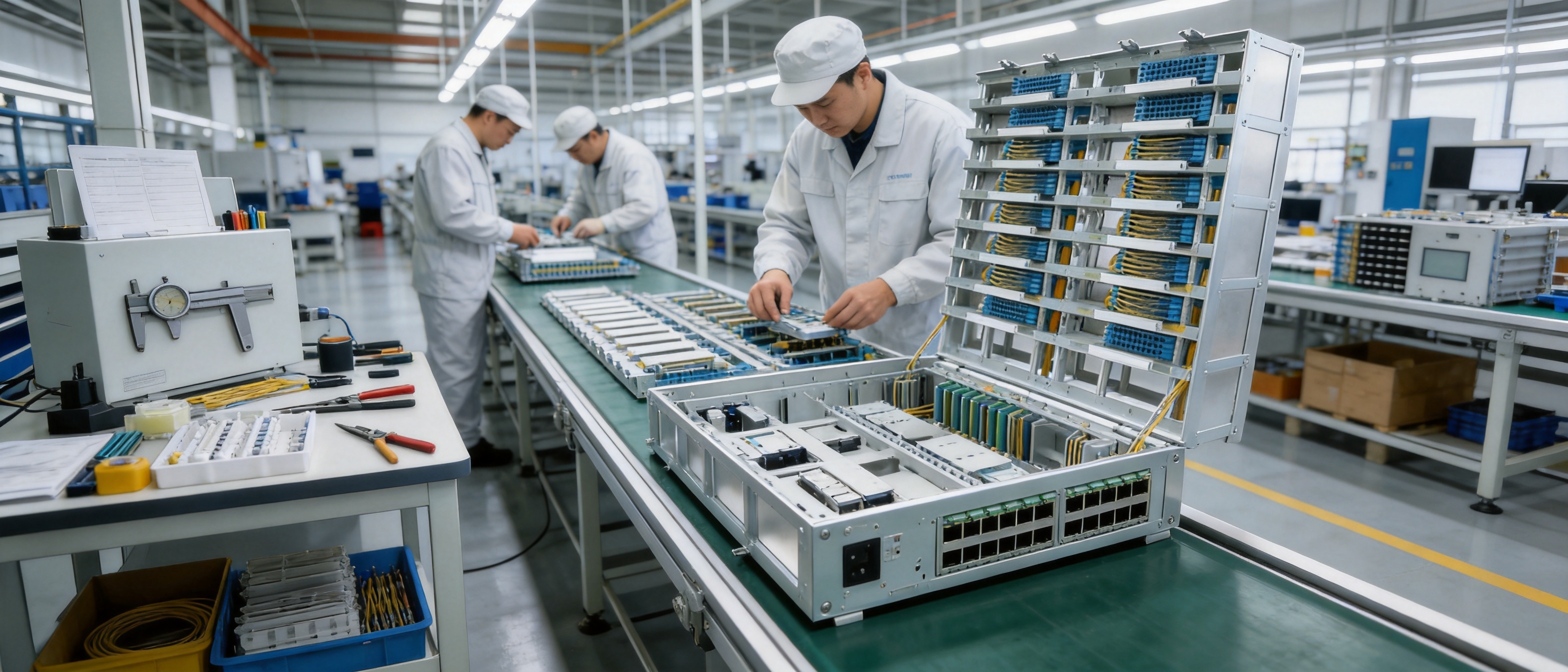
The aluminum alloy frame requires controlled manufacturing processes to achieve reliable alignment, consistent module positioning, and repeatable assembly. Typical quality-focused production stages for this type of equipment include engineering review, material verification, cutting or forming, surface treatment, frame assembly, dimensional inspection, module integration, and final inspection.
Accurate fabrication is particularly important for a high-density optical frame. Small dimensional deviations can affect tray alignment, door or panel fit, cable routing clearance, and the ease of adding modules. Consistent manufacturing helps ensure that the installed system behaves as intended across different projects.
Surface treatment is also an important consideration for aluminum alloy structures. A suitable finish can support appearance, durability, handling safety, and resistance to normal equipment-room conditions. The exact treatment should be confirmed according to the ordered configuration and project specification, but the material selection itself provides a useful foundation for a durable open frame.
6.3 Modular Assembly and Configuration Control
The integrated tray concept supports a modular production approach. Modules can be prepared, inspected, and assembled according to a defined configuration before shipment. This helps improve repeatability and reduces the amount of complex work required at the installation site.
Configuration control is essential when several capacities and frame arrangements are available. Manufacturing documentation should identify the selected model, capacity, dimensional arrangement, external line side, internal line side, testing-port provisions, and accessory requirements. Clear configuration management reduces the possibility of a mismatch between the project order and the delivered equipment.
6.4 Quality-Oriented Production Practices
For communication infrastructure, quality is not limited to visual appearance. It includes dimensional consistency, structural integrity, reliable module installation, smooth access, secure cable support, correct labeling, and the ability to maintain the frame over many years.
A quality-oriented production process therefore includes inspection at multiple stages rather than relying only on a final visual check. Incoming material checks, assembly inspections, functional verification of modular components, and final packing inspections can contribute to more consistent delivery.
Wanma Technology emphasizes reliable product quality and timely delivery. These strengths are particularly relevant to large communication-room projects, where delayed frames or incorrect accessories can affect cable installation schedules, equipment commissioning, and overall project coordination.
6.5 Customized Integrated Solutions
Communication rooms rarely have identical layouts. Floor space, cable entry direction, equipment placement, working aisles, expansion plans, and maintenance rules can differ from one site to another. A manufacturer that can provide integrated and customized solutions can help address these differences more effectively than a supplier offering only a rigid standard product.
Customization may involve configuration selection, capacity planning, tray arrangements, accessory coordination, documentation, packaging, and delivery planning. The objective is not to change every product for every project, but to provide a reliable standard platform that can be configured in a controlled way for the intended application.
7. Manufacturing Process from Design to Delivery
A dependable optical main distribution frame begins with a clear engineering process. The first stage is application analysis. The manufacturer and customer identify whether the system will be installed in a new communication room, a central equipment room, or a converted optical measuring room. The expected fiber count, access method, frame orientation, and future expansion requirements are then reviewed.
The second stage is configuration selection. The project team selects a double-sided or single-sided structure and determines the required capacity. The relationship between external line capacity, internal line capacity, testing ports, and jumper routing must be checked before production begins.
The third stage is mechanical and modular design review. Engineers verify frame dimensions, aluminum alloy structure, tray compatibility, working clearances, cable entry paths, and the division of the three functional areas. This review helps ensure that the frame can be installed and operated within the customer’s available room space.
The fourth stage is material preparation. Aluminum alloy structural components, trays, optical distribution modules, cable management accessories, fastening parts, and identification materials are prepared according to the approved configuration. Material control is important because inconsistent components can affect final assembly quality.
The fifth stage is structural fabrication. The frame components are produced and finished to the required dimensions. Edges, mounting points, support interfaces, and tray positions are checked to ensure that the final assembly can be completed accurately.
The sixth stage is modular assembly. Functional trays and related components are installed according to the selected capacity. The external line side and internal line side are reviewed for correct positioning. The cable stripping area, splicing and distribution area, and jumper fiber area are checked as an integrated working system rather than as unrelated parts.
The seventh stage is inspection and configuration verification. Inspectors can review dimensions, frame alignment, module interchangeability, fastening security, access conditions, and the correct quantity of supplied components. Where software-assisted jumper planning is included, the relevant system configuration and operating information should also be checked.
The final stage is packaging and delivery preparation. Because optical distribution frames may include many modular components, packaging must protect the structure from impact and prevent small accessories from being separated or lost. Clear packing lists and project documentation support faster installation at the customer site.
This process-based approach helps transform a product specification into a repeatable installation result. It is especially important for international projects, where the delivered equipment may be installed by a local team that depends on accurate documentation and clear configuration information.
8. Installation and Operation Considerations
Before installation, the communication room should be checked for floor conditions, access routes, ceiling height, cable entry locations, equipment placement, working aisles, lighting, grounding requirements, and environmental conditions. The selected frame dimensions should be compared with the actual site plan.
The frame should be positioned so that technicians can access the intended working sides. Double-sided configurations require suitable clearance for operation and maintenance from both sides. Single-sided configurations should be positioned according to the approved access method and the room’s cable routing plan.
Incoming cables should be secured before individual fibers are directed into the stripping and splicing areas. Cable slack should be managed carefully to avoid excessive tension. Fiber routing should respect the applicable bending requirements of the installed cable and fiber assemblies.
Splicing and distribution work should be documented during installation. Each external line, internal line, splice location, distribution position, and testing port should have a clear identification method. Accurate records help technicians locate connections quickly during future maintenance.
Patch cords should be routed through the designated jumper fiber area and hung on the appropriate side of the frame. The software-recommended lengths should be used as a planning reference, while the installer should still verify the physical path and final slack requirements at the site.
After installation, the frame should be inspected for routing order, label accuracy, access clearance, cable security, module installation, and visible signs of excessive bending or strain. Test records should be associated with the corresponding fiber and port identification.
9. Applications Across Communication Networks
9.1 Central Equipment Rooms
Central equipment rooms often contain a high concentration of optical connections and require clear separation between incoming network cables and equipment-side connections. The GPX129-OMDF provides a structured platform for this environment, allowing operators to expand capacity while maintaining organized access.
9.2 Ethernet Optical Networks
Ethernet optical networks require dependable physical management as bandwidth and connection density increase. The OMDF can support the transition between external optical infrastructure and internal network equipment, making it easier to manage changes in service allocation and equipment connectivity.
9.3 Railway and Urban Rail Transit Systems
Railway and urban rail transit systems depend on communication networks for operational control, passenger information, surveillance, signaling support, and administrative services. These networks often include distributed stations, central control locations, and equipment rooms with strict maintenance requirements.
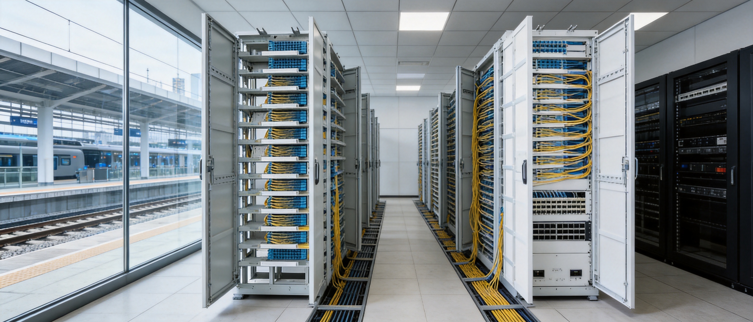
An orderly optical distribution frame can help transit operators document and maintain fiber connections across complex communication infrastructures. Wanma Technology’s products are used in national high-speed railway and urban rail transit environments, giving the company experience relevant to infrastructure projects where reliability, clarity, and long-term serviceability are important.
9.4 5G and FTTH Modernization Projects
5G and fiber-to-the-home modernization programs increase the need for scalable optical management. Although access networks may use different distribution architectures, the central principle remains the same: optical connections must be terminated, organized, identified, tested, and modified without creating unnecessary disruption.
The GPX129-OMDF can serve as part of a broader modernization infrastructure strategy, particularly where an operator is converting existing communication-room functions to optical fiber management and requires a high-capacity, modular frame.
9.5 Enterprise and Campus Networks
Large enterprises, industrial campuses, universities, hospitals, and public institutions may operate central communication rooms that connect multiple buildings and service areas. These sites benefit from a distribution system that can accommodate growth, simplify troubleshooting, and separate permanent cable connections from frequently changed equipment jumpers.
10. Maintenance, Expansion, and Lifecycle Value
The value of an optical main distribution frame should be evaluated over its full operating lifecycle rather than only by its initial purchase price. Installation labor, troubleshooting time, expansion effort, spare-parts requirements, documentation quality, and service interruption risk all affect the total cost of ownership.
The GPX129-OMDF supports lifecycle value through its open structure and organized working areas. Technicians can access the relevant components more directly, which may reduce the time required for inspection and connection changes. The separated zones also help protect established cable arrangements when maintenance is performed in another area.
Module interchangeability can simplify replacement and expansion planning. If the same integrated tray concept is used across the external and internal sides, operators may be able to standardize training and inventory. This is especially useful for organizations that manage multiple communication rooms or network sites.
Capacity expansion should be planned before the frame reaches a congested condition. Spare positions, future cable routes, additional testing requirements, and jumper storage should be considered as part of the initial design. A modular frame is most effective when its expansion capability is supported by a disciplined capacity-management policy.
Maintenance teams should periodically review labels, patch-cord routing, test records, and unused connections. Abandoned jumpers should be removed according to the operator’s procedures. Changes should be documented promptly so that the physical frame and network records remain consistent.
11. Project Selection Guide
When selecting a GPX129-OMDF configuration, project planners should begin with the total number of external and internal fiber cores. They should then determine the number of active connections, spare positions, testing ports, and expected growth over the planning period.
The next consideration is room layout. A double-sided frame may be appropriate where access is available from both sides and where the operator wants a clear physical separation between working directions. A single-sided configuration may be better where the frame is positioned against a wall or where the room has a designated front-access maintenance aisle.
Environmental and operational conditions should also be reviewed. The room should provide suitable protection from water, dust, excessive vibration, unauthorized access, and other conditions that could affect optical infrastructure. Grounding, cable support, fire-safety requirements, and local installation regulations should be addressed in the project design.
Finally, the customer should confirm the full configuration with the manufacturer before ordering. This includes the exact model code, dimensions, capacity allocation, testing-port arrangement, accessories, software functions, packaging, documentation, and delivery schedule.
12. Frequently Asked Questions
12.1 What is the primary application of the GPX129-OMDF?
The GPX129-OMDF is designed for independent fiber patching areas in newly built communication equipment rooms and central equipment rooms. It is also suitable for projects that convert a former cable measuring room into an optical fiber measuring room after an existing main distribution frame is removed.
12.2 What management method does the system use?
The system adopts a traditional main distribution frame management mode. This allows operators to manage external lines, internal lines, splicing, distribution, testing ports, and jumper connections within a familiar structured framework.
12.3 Why is the frame divided into three functional areas?
The three areas separate cable stripping, splicing and distribution, and jumper fiber management. This separation supports independent operation, improves accessibility, reduces congestion, and helps prevent one maintenance activity from interfering with another.
12.4 What is the advantage of the open aluminum alloy structure?
The open structure improves visibility and access for patching, inspection, capacity expansion, and installation. Aluminum alloy provides a practical combination of strength, relatively low weight, and suitability for communication-room equipment.
12.5 Are the external and internal line sides designed differently?
Both sides adopt the same integrated tray design. This supports module interchangeability and improves adaptability when the network configuration changes or additional capacity is required.
12.6 How are patch cords managed?
Patch cords are hung on both sides of the frame to prevent interweaving and maintain orderly routing. The equipped software system can also calculate and recommend suitable jumper lengths.
12.7 Does the listed capacity include testing ports?
The capacity note for the double-sided configurations states that the external line-side and internal line-side capacities exclude testing ports. Customers should confirm the required testing-port arrangement during project planning and ordering.
12.8 Can the frame be used for network expansion?
Yes. The open frame structure, modular tray design, and available capacity options support capacity expansion. Expansion should be planned according to the room layout, spare capacity, cable routing, and future service requirements.
12.9 Is the product suitable for railway communication networks?
The product is suitable for communication-room applications in infrastructure networks when the selected configuration meets the project’s technical and environmental requirements. The manufacturer has experience supplying communication products for high-speed railway and urban rail transit systems.
12.10 Can customized configurations be requested?
The manufacturer develops and produces its own products and also provides integrated solutions for customized products. The exact scope of customization should be discussed and confirmed according to the project’s capacity, layout, accessories, and documentation requirements.
12.11 What should be confirmed before ordering?
Customers should confirm the frame type, model, dimensions, external and internal line capacity, testing-port requirements, access direction, module arrangement, accessories, software requirements, delivery schedule, and installation documentation.
12.12 How does the product support maintenance?
The open structure, separated functional zones, integrated trays, and organized jumper routing make it easier to inspect, trace, modify, and expand the optical connections. Clear labeling and accurate records remain essential for effective maintenance.
13. Why Manufacturer Capability Matters
An optical main distribution frame is a long-term infrastructure product. Its value depends not only on the frame itself but also on the manufacturer’s ability to provide consistent production, accurate configuration, dependable delivery, technical coordination, and continuing project support.
Wanma Technology Co., Ltd. has operated since 1997 and specializes in communication cabinets, communication electronic equipment, and passive optical components. This product scope is directly related to the mechanical and optical requirements of OMDF systems.
The company’s products are used in Ethernet networks, optical communication networks, central equipment rooms, high-speed railway systems, and urban rail transit systems. Its experience across these application areas supports a practical understanding of how communication infrastructure must function in real operating environments.
The company maintains a sales network covering more than 20 countries and regions, including the United States, Australia, the United Kingdom, Italy, South Africa, and Ghana. International project experience can be valuable when customers require coordinated production, export packaging, technical documentation, and delivery planning.
Wanma Technology emphasizes reliable quality, timely delivery, and long-term strategic partnerships. These priorities align with the needs of network operators and system integrators that require stable supply and consistent support across multiple projects.
14. Conclusion
The GPX129-OMDF optical main distribution frame provides a structured solution for high-capacity fiber management in communication equipment rooms and central equipment rooms. Its open aluminum alloy frame improves access and visibility, while the three-zone structure separates cable stripping, splicing and distribution, and jumper fiber operations.
The same integrated tray design on the external and internal line sides supports interchangeability and adaptability. Bilateral jumper hanging helps prevent interweaving, and software-assisted jumper length recommendations support more efficient planning. Multiple double-sided and single-sided capacity options allow the frame to be matched to different network sizes and room layouts.
Compared with less-structured alternatives, the system offers practical advantages in accessibility, organization, expansion, and maintenance. It is suitable for new construction as well as modernization projects in which existing cable measuring rooms are converted into optical fiber measuring rooms.
The manufacturer’s experience in communication cabinets, passive optical components, communication electronic equipment, Ethernet networks, railway systems, and optical communication infrastructure strengthens the product’s application value. Its in-house development, manufacturing capability, modular approach, customized solution experience, and international delivery network provide a solid foundation for communication infrastructure projects.
For operators planning a reliable and scalable optical distribution environment, the GPX129-OMDF represents a balanced combination of high-density capacity, accessible design, organized fiber management, and lifecycle adaptability.
References
1. Wanma Technology Co., Ltd., GPX129-OMDF Optical Main Distribution Frame Product Information and Ordering Guide.
2. International Electrotechnical Commission, Optical Fibre Cables and Passive Optical Infrastructure Standards.
3. Telecommunications Industry Association, Telecommunications Infrastructure Standards for Optical Fiber Cabling.
4. International Organization for Standardization and International Electrotechnical Commission, Generic Cabling Systems for Customer Premises.
5. Fiber Optic Association, Reference Materials on Fiber Optic Installation, Splicing, Testing, and Maintenance.
6. Telecommunications Infrastructure Planning References for Central Equipment Rooms and Optical Distribution Systems.
Product: Fiber Solution-Optical Main Distribution Frame---GPX129-OMDF
PREV:Fiber Solution-Drop Cables for Reliable FTTH Deployment and Network Modernization
NEXT:576-Core Double-Sided SMC Fiber Optic Cable Distribution Box: Outdoor Capacity, Protection, and Network Management
NEXT:576-Core Double-Sided SMC Fiber Optic Cable Distribution Box: Outdoor Capacity, Protection, and Network Management
Interested in cooperation or have questions?
Related products
-
-
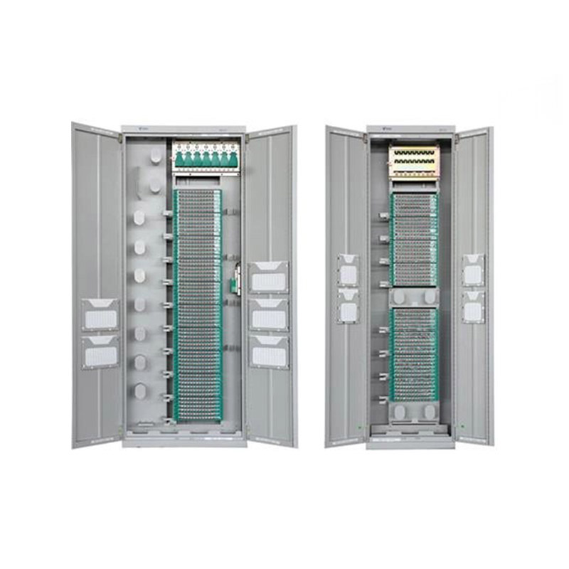
Application ScopeThe GPX129-09T fiber optic distribution frame is used to connect, distribute, and manage fiber optic cables and optical communication equipment. It is suitable for large-capacity fibe...
See Details -
Application ScopeThe GPX129BKC fiber optic distribution frame is used to connect and distribute optical cables to optical communication equipment, and is suitable for large-capacity fiber optic commun...
See Details -
Application Used in FTTH network access-layer equipment rooms where splitting, splicing, distribution and other operations need to be carried out within a frame. Used in FTTH networks where optical sp...
See Details
Ready to Get started ? Contact Us Now !

Product.
Contact Details.
-
 +86 13958188250
-
 +86 13958188250
-
 [email protected]
-
 AUDIT Email:[email protected]
- Wanma Industrial Park Taihu Yuan Town Lin'an District Hangzhou City China.
QR Code

Copyright © Wanma Technology Co., Ltd. All Rights Reserved.
Privacy
Custom Ethernet Optical Network Railway Transit Equipments Suppliers
