

 English
 Français
 Español
 Português
 عربى






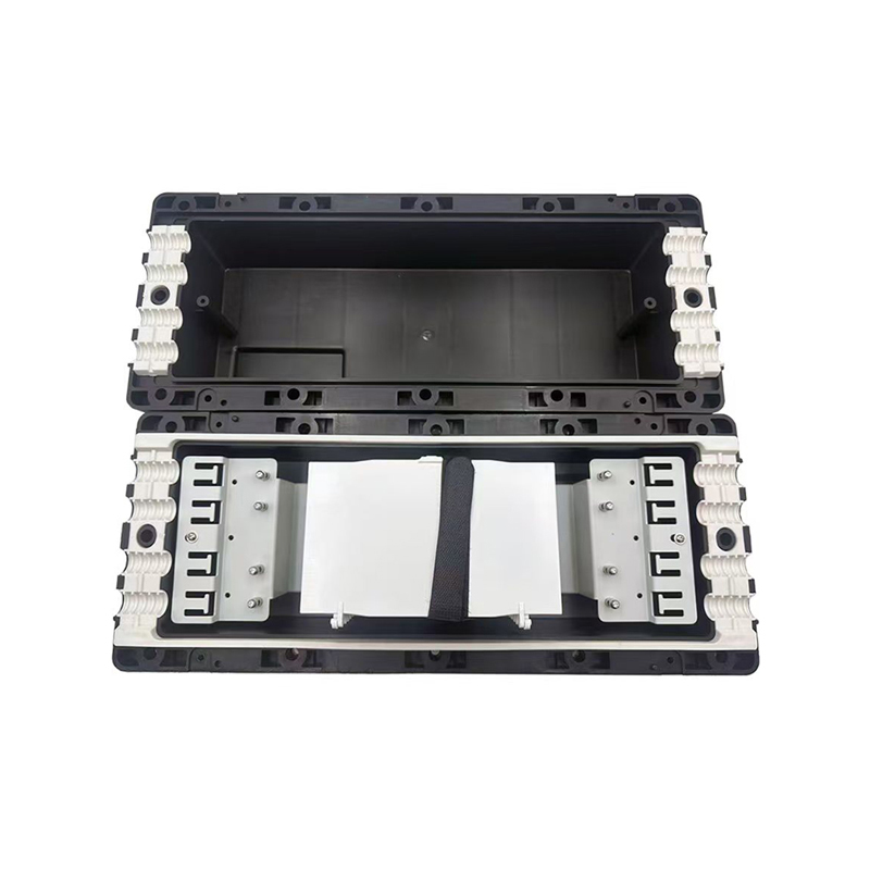
OverviewModel No. JR-2001-H10 is one of the main equipment for user access points, applied for protective connection and distribution between two or more cables. The primary function is to connect dis...
See DetailsWM-2001-H10 Fiber Optic Splice Closure: Reliable Protection and Flexible Distribution for Modern Optical Networks
Content
- 1 Introduction
- 2 Product Overview
- 3 Key Technical Specifications
- 4 Protection Against Environmental Exposure
- 5 Internal Fiber Organization
- 6 Installation Flexibility for Outdoor and Access Networks
- 7 Advantages Compared with Basic Splice Enclosures
- 8 Engineering Plastic Construction
- 9 Manufacturing Strengths and Production Discipline
- 10 Application in Ethernet and Optical Communication Networks
- 11 Use in Railway and Urban Transit Infrastructure
- 12 Installation Method and Best Practices
- 13 Maintenance and Long-Term Serviceability
- 14 Why Manufacturing Experience Matters to Buyers
- 15 Comparison with Alternative Product Types
- 16 Project Planning Considerations
- 17 Role in 5G and FTTH Modernization
- 18 Frequently Asked Questions
- 18.1 What is the primary purpose of the WM-2001-H10?
- 18.2 How many fibers can the closure accommodate?
- 18.3 Is the closure suitable for outdoor installation?
- 18.4 What material is used for the housing?
- 18.5 How many cable ports are provided?
- 18.6 What sealing method is used?
- 18.7 Can the product be used for FTTH networks?
- 18.8 Can it be used in railway or urban transit projects?
- 18.9 Does the closure include six splice trays?
- 18.10 What are the product dimensions?
- 18.11 Why is fiber routing important inside a splice closure?
- 18.12 Is the closure completely maintenance-free after installation?
- 18.13 What should buyers confirm before placing an order?
- 19 Conclusion
- 20 References
- 21 Product: WM-2001-H10 Fiber Optic Splice Closure
Introduction
Fiber optic networks depend on more than cables and active transmission equipment. Every connection point must be protected from water, dust, mechanical stress, accidental impact, and installation errors. A failure at a splice location can interrupt an entire service segment, increase maintenance costs, and create difficult troubleshooting conditions. For this reason, a properly engineered fiber optic splice closure is an essential part of outside-plant communication infrastructure.
The WM-2001-H10 Fiber Optic Splice Closure is designed to protect and organize fiber connections between two or more cables. It is intended for user access points and can be installed in underground or aerial applications. With a capacity of up to 144 cores, six splice trays, three inlet ports, and three outlet ports, the closure provides a practical platform for distribution, cable branching, and fiber management in communication networks.
Its application range includes communication systems, cable television networks, optical cable network systems, Ethernet infrastructure, and fiber-to-the-home deployment. It can also support optical communication installations associated with transportation, railway, and urban rail transit environments when the installation design and environmental requirements are properly matched to the site.
The enclosure combines a high-strength PP+GF material structure, an IP68 protection level, screw mechanical sealing for cable entries, and a fiber routing design that protects bending radius while preserving storage space. These features help installers build organized, serviceable, and durable optical connections without relying on unnecessarily complicated installation procedures.
Product Overview
The main function of the WM-2001-H10 is to provide a protected location for fiber splicing and distribution. In a typical network, an outdoor distribution cable may need to be connected to one or more branch cables, indoor cables, or access cables. The splice closure houses these connections and protects them from environmental exposure.
The product is especially suitable for locations where a compact but relatively high-capacity closure is required. Its six splice trays provide an overall capacity of 144 cores, with each tray supporting up to 24 cores. This arrangement allows the installer to divide fibers into manageable groups instead of placing all splices in one congested area.
The closure has three inlet ports and three outlet ports. This configuration provides flexibility for cable routing and makes the unit suitable for straight-through, branching, and distribution applications. The stated inlet and outlet cable port sizes include diameters of 16 mm, 20 mm, and 23 mm. Such flexibility allows the closure to accommodate several common cable dimensions within the specified installation range.
The black enclosure is manufactured from PP+GF, a glass-fiber-reinforced polypropylene material. This material combination is intended to provide a useful balance between strength, weight, weather resistance, and manufacturing efficiency. Compared with a conventional unreinforced plastic enclosure, reinforced material can provide improved structural stability in applications where the housing may experience handling loads, installation pressure, vibration, or long-term outdoor exposure.
The closure measures approximately 395 × 190 × 110 mm. Its relatively compact dimensions make it easier to install in constrained spaces while still providing sufficient internal room for splice trays, cable routing, and fiber storage. The product is supplied in packaging designed for individual protection and bulk shipment, with ten units per carton and a stated carton weight of 21 kg.
Key Technical Specifications
| Item | Specification |
|---|---|
| Product model | WM-2001-H10 |
| Product type | Fiber optic splice closure |
| Color | Black |
| Maximum capacity | 144 cores |
| Splice tray quantity | 6 trays |
| Capacity per tray | 24 cores |
| Protection level | IP68 |
| Housing material | PP+GF |
| Inlet and outlet configuration | 3 + 3 |
| Product dimensions | 395 × 190 × 110 mm |
| Inlet cable port sizes | 16 mm, 20 mm, and 23 mm |
| Outlet cable port sizes | 16 mm, 20 mm, and 23 mm |
| Inlet sealing method | Screw mechanical sealing |
These specifications make the WM-2001-H10 suitable for many low- and medium-density outdoor fiber distribution points. The exact application should always be evaluated according to cable type, installation method, environmental conditions, local regulations, and the required splice technology. The closure provides the physical platform, while the installer remains responsible for selecting compatible splice protectors, cable preparation procedures, and mounting hardware.
Protection Against Environmental Exposure
One of the most important advantages of an outdoor splice closure is environmental protection. Optical fibers can transmit data over long distances, but exposed splice points remain vulnerable to moisture, dust, condensation, insects, and physical damage. A closure must therefore do more than simply cover the splice. It must create a controlled internal environment and maintain protection around cable entry points.
The WM-2001-H10 is specified with an IP68 protection level. In general terms, IP68-rated equipment is designed to offer a high level of protection against dust ingress and water exposure when installed according to the applicable product and test conditions. The actual performance of any installed closure depends on proper cable preparation, correct sealing, suitable fastener tightening, and adherence to the installation instructions.
The screw mechanical sealing method provides a practical way to secure cable entries. Instead of depending only on adhesives or temporary compression, a mechanical sealing arrangement can be checked during installation and service. It also supports a more structured installation process because the installer can identify the cable entry, position the sealing components, and secure the assembly with controlled mechanical force.
Weather protection is particularly important in fiber-to-the-home networks, roadside communications, cable television systems, and railway-related infrastructure. These installations may experience rain, temperature changes, dust, vibration, and repeated maintenance activity. A properly closed and sealed enclosure helps keep the optical splice area stable under these conditions.
The high-quality engineering plastic body also reduces dependence on metallic housing materials. A plastic closure does not require corrosion protection in the same way as untreated metal. This can be valuable in humid environments, coastal areas, underground chambers, and locations where chemical exposure is possible. The PP+GF housing is intended to provide a durable external shell while keeping the product manageable for field technicians.
Internal Fiber Organization
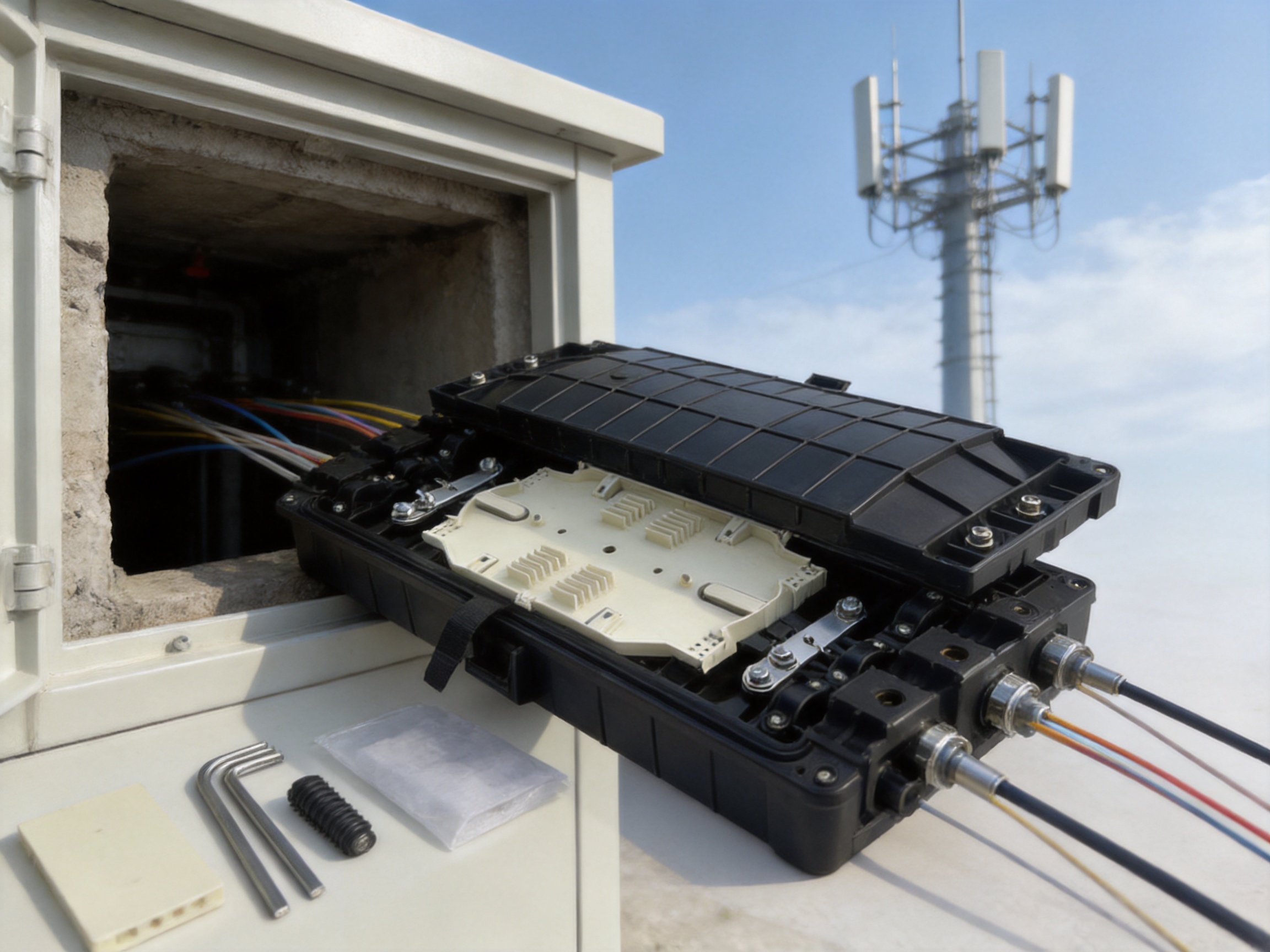
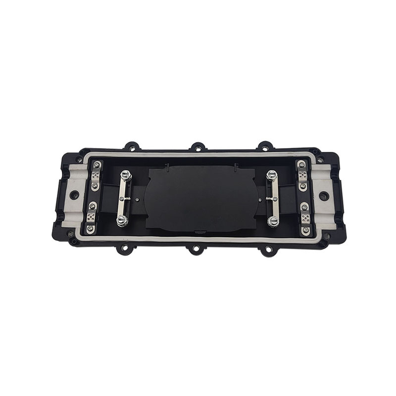
Fiber management is a major factor in splice reliability. A closure may be physically strong, but poor internal organization can cause excessive bending, tangled fibers, difficult maintenance, or accidental damage during re-entry. The WM-2001-H10 addresses this issue through its multi-tray structure and fiber routing design.
Six splice trays divide the 144-core capacity into six separate working areas. Each tray can accommodate up to 24 cores, allowing technicians to group fibers according to cable direction, service area, customer segment, or network design. This makes the internal arrangement easier to inspect and reduces the likelihood that one maintenance task will disturb unrelated fibers.
The fiber routing design is intended to preserve the required radius curvature of the fiber. Optical fiber should not be bent beyond the minimum bend radius specified by the cable or fiber manufacturer. Excessive bending may result in higher optical loss, unstable performance, or long-term mechanical stress. By providing a defined route and storage area, the closure helps the installer handle slack fiber in a more controlled manner.
Fiber storage space is equally important. During splicing, a technician generally needs enough extra fiber to position the splice correctly, perform testing, and complete future maintenance. Insufficient storage can force sharp bends or tightly packed loops. The WM-2001-H10 is designed with enough internal space to support organized fiber storage around the splice trays.
A well-organized tray system also improves fault diagnosis. When fibers are separated logically, technicians can identify cable paths, locate individual splice groups, and carry out optical testing with less disruption. This is particularly useful in networks that expand over time. A closure installed with clear routing at the beginning is easier to upgrade than one where all fiber slack is mixed together.
Installers should nevertheless follow the cable manufacturer’s bend-radius requirements and the closure’s installation procedures. The product design assists good practice, but performance depends on how the fibers are prepared, routed, secured, and labeled in the field.
WM-2001-H10 Fiber Optic Splice Closure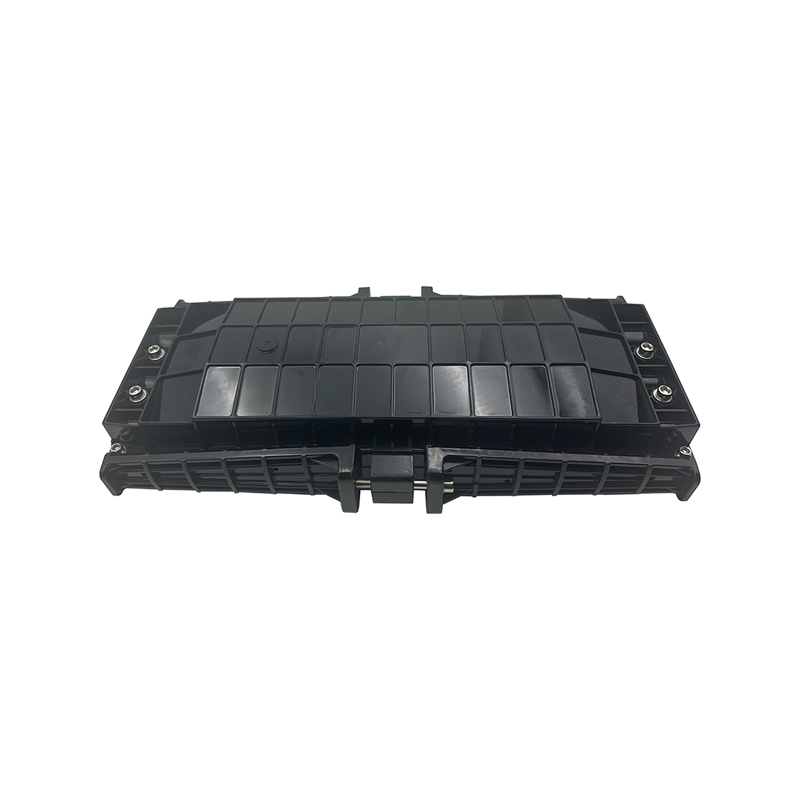
Installation Flexibility for Outdoor and Access Networks
The WM-2001-H10 is designed for both underground and aerial use. This gives network designers more freedom when planning distribution routes. Underground applications may include handholes, utility chambers, buried access points, and other protected infrastructure locations. Aerial applications may include pole-mounted or messenger-supported communication routes, subject to appropriate mounting accessories and site engineering.
In an underground installation, the closure may be exposed to moisture, soil movement, condensation, and limited working space. Its waterproof design and IP68 specification are important in this environment. The installer must ensure that the enclosure is positioned correctly, cable entries are sealed, and the closure is not subjected to loads for which it was not designed.
In an aerial application, mechanical support and mounting orientation are essential. The closure should be secured using suitable hardware, and the cable should be supported so that its weight is not transferred directly to the splice area. Wind, vibration, ice, and temperature variation should also be considered during project planning.
The three-inlet and three-outlet configuration allows several deployment patterns. A straight-through cable route may use one inlet and one outlet, while additional ports can support branch cables or future expansion. In a distribution application, the main cable can enter through one side and branch cables can leave through several available ports. The actual port arrangement should be selected according to the network drawing and the cable diameter.
The range of 16 mm, 20 mm, and 23 mm cable port sizes adds practical flexibility. A closure that accepts only one cable diameter may require additional adapters or a different housing for each cable type. Multiple port sizes can simplify inventory planning and reduce the need to select a separate product for every access point.
Advantages Compared with Basic Splice Enclosures
Basic splice enclosures may provide only a shell around the splice, leaving the installer to manage fiber organization, cable branching, and sealing with separate components. The WM-2001-H10 offers a more complete internal and external arrangement. Its advantages are not based on a single feature, but on the combination of capacity, sealing, routing, and installation flexibility.
Higher Practical Capacity
With a capacity of 144 cores, the WM-2001-H10 can serve networks that have outgrown small closures. Six trays with 24 cores each provide a structured method for managing a relatively large number of splices. This can reduce the need to install several small closures in the same area, which may lower the number of housings, mounting locations, and inspection points required for a project.
Better Fiber Separation
A single crowded splice area can make installation and maintenance difficult. The six-tray configuration provides clearer separation. Technicians can reserve individual trays for different cables, services, or phases of network construction. This is an advantage over simple enclosures that do not offer an organized tray system.
More Adaptable Cable Entry
The 3+3 inlet and outlet arrangement supports multiple cable directions and branch routes. Together with 16 mm, 20 mm, and 23 mm cable port options, this configuration is more adaptable than a closure with a fixed pair of cable entries. It supports network changes while preserving a compact installation footprint.
Improved Environmental Protection
The IP68 protection level and waterproof body design provide a higher level of environmental protection than an enclosure intended only for sheltered indoor locations. This makes the product more appropriate for exposed access points, underground chambers, and other outdoor network environments.
Serviceable Mechanical Sealing
Screw mechanical sealing offers a repeatable approach to cable entry protection. Compared with improvised sealing methods, a dedicated mechanical design is easier to understand, inspect, and maintain. The installer can verify the condition of the sealing components and the mechanical fastening during commissioning or service.
Efficient Use of Installation Space
The 395 × 190 × 110 mm dimensions provide a balance between internal capacity and external size. The closure is large enough for six splice trays but compact enough for many access-point applications. This can be beneficial where cabinets, poles, chambers, or wall spaces have limited room.
Engineering Plastic Construction
The housing material is PP+GF, or glass-fiber-reinforced polypropylene. Polypropylene is widely used in technical products because it is lightweight, chemically resistant, and suitable for forming complex housing shapes. The addition of glass fiber can improve rigidity and structural strength compared with standard polypropylene.
Material selection affects every stage of a splice closure’s life cycle. During manufacturing, the material must flow consistently into the mold and reproduce sealing surfaces, ribs, mounting features, tray supports, and other details. During assembly, the housing must remain dimensionally stable enough for the cover and sealing system to fit correctly. During field use, it must withstand normal handling and environmental exposure.
A reinforced plastic housing can also help reduce overall product weight. This is useful for aerial deployment and for technicians who must carry multiple closures and tools to remote installation locations. Lower weight may simplify handling, although the final mounting design must always account for the complete installed assembly, including cables and accessories.
The black color is practical for outdoor communication equipment. It provides a consistent professional appearance and can help the housing blend into many utility environments. More importantly, the color and material system should remain consistent throughout production so that products supplied for different projects have a uniform visual and dimensional quality.
Material quality alone does not guarantee long-term performance. The manufacturing process must control resin preparation, glass-fiber distribution, molding conditions, cooling, trimming, and inspection. A reliable manufacturer therefore needs a systematic approach to process control rather than simply selecting a suitable raw material.
Manufacturing Strengths and Production Discipline
The product is manufactured by a company with experience in communication cabinets, communication electronic equipment, and passive optical components. Established in 1997, the manufacturer has developed a product portfolio serving Ethernet networks, optical communication networks, central equipment rooms, high-speed railway infrastructure, and urban rail transit systems.
This industry background is significant because fiber optic splice closures must be produced with attention to both mechanical and optical requirements. A housing can be attractive but unsuitable if the internal tray supports are inaccurate, the cable entry dimensions vary, or the sealing surfaces are inconsistent. Experience across communication equipment categories helps a manufacturer understand how enclosure design interacts with field installation, cable routing, network maintenance, and equipment-room planning.
Product Development and Design Integration
The WM-2001-H10 reflects an integrated design approach. The capacity, tray arrangement, cable ports, sealing method, and dimensions are considered together rather than as isolated features. This approach helps create a product that can be manufactured efficiently and installed consistently.
Design integration is particularly important for plastic closures. The housing must provide enough wall thickness and reinforcement for strength while avoiding unnecessary material use. The cover, base, tray supports, and entry components must fit together accurately. Internal clearance must be sufficient for fiber routing, but the overall enclosure should remain compact.
Manufacturing-oriented design can also improve repeatability. Features that are clearly defined for molding and assembly are less dependent on manual adjustment. This supports consistent dimensions across production batches and helps distributors and network contractors receive products that behave predictably during installation.
Precision Plastic Molding
The PP+GF housing requires controlled plastic molding. Important process variables include material drying or preparation, melt temperature, injection pressure, filling speed, mold temperature, cooling time, and part ejection. Variations in these conditions can affect warpage, surface quality, dimensional accuracy, and mechanical performance.
For a splice closure, dimensional control is especially important around the cover interface and cable entry sections. If the housing is distorted, the sealing system may not compress evenly. If tray supports are misaligned, the installer may encounter difficulty when placing or removing the splice trays. A mature production process therefore combines suitable mold design with inspection of critical dimensions.
Assembly and Component Control
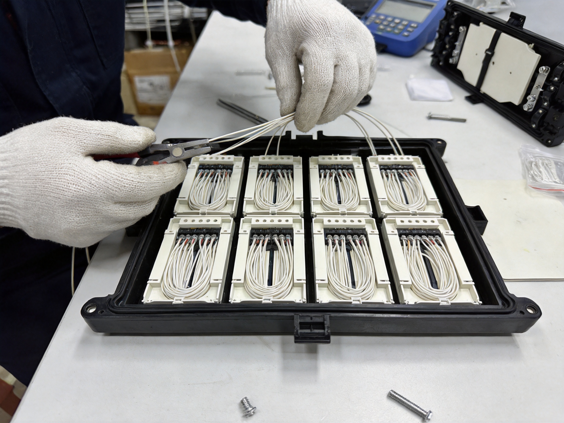
After molding, the housing components must be inspected, trimmed, and assembled with the mechanical sealing parts and internal fiber management components. Assembly control helps ensure that screws, seals, trays, brackets, and other parts are correctly positioned.
Because the closure is intended for field installation, assembly should be clear and repeatable. Components that are easy to identify reduce the risk of incorrect placement. A well-controlled assembly process also reduces the possibility of missing parts, inconsistent fastening, or damage to sealing components before the product reaches the customer.
Quality Inspection
Quality inspection for a splice closure may include visual inspection, dimensional checks, material and component verification, sealing assessment, and functional inspection of the tray system. The specific tests applied depend on the manufacturer’s quality system, project requirements, and applicable standards.
Visual inspection can identify scratches, molding defects, incomplete filling, contamination, or damage to the housing. Dimensional checks can confirm that the product remains within design tolerances. Mechanical inspection can verify the fit of the cover, the operation of cable entry components, and the stability of the splice trays.
Sealing-related inspection is also essential. An enclosure may have an IP68 design, but the final result depends on the condition and correct installation of the seals. Production inspection should therefore focus on the surfaces and components that contribute to water and dust protection. Customers should follow the supplied installation instructions and conduct any required site-level testing.
Packaging and Logistics
Packaging is an important part of manufacturing quality because the closure can be damaged during transport even when it leaves the production line in perfect condition. The stated packaging includes a plastic bag, an inner corrugated box, and a double-corrugated outer carton. Ten pieces are packed per carton, with a stated carton weight of 21 kg.
Individual protection helps prevent surface abrasion and contact damage. The inner box provides separation and structural support, while the stronger outer carton is suitable for warehouse handling and shipment. Consistent packaging dimensions also help distributors plan storage and transportation.
For international projects, packaging must be coordinated with shipping conditions, warehouse duration, humidity, handling practices, and local distribution requirements. Clear product labeling and batch traceability can further support project management and after-sales service.
Application in Ethernet and Optical Communication Networks
Ethernet networks increasingly rely on fiber optic cables for backbone connections, distribution links, industrial communications, and access infrastructure. The WM-2001-H10 can be used at selected passive connection points within these networks. It does not replace active Ethernet equipment such as switches or optical network terminals. Instead, it protects the physical fiber splices that allow those active devices and network segments to connect.
In a campus or industrial Ethernet network, the closure may be positioned between a backbone cable and branch cables serving buildings, production areas, security systems, or remote cabinets. In a residential access network, it may support the transition between a distribution cable and several feeder or drop routes. In a cable television network, it can protect optical connections used to distribute signals between network segments.
The product is also relevant to broader 5G and FTTH modernization programs. Although 5G radio equipment may be wireless at the final access point, the supporting transport and backhaul networks commonly depend on fiber. Fiber closures help create the physical connectivity required between aggregation points, cabinets, base-station sites, and access nodes.
For FTTH deployment, capacity planning is important. A closure that is too small may quickly become congested as customers are added. A closure with multiple trays and 144-core capacity can provide a more scalable connection point, subject to the actual fiber count and network architecture. The six-tray layout may also help separate active service fibers from reserved or future-use fibers.
Use in Railway and Urban Transit Infrastructure
Railway and urban transit communication systems require carefully planned optical infrastructure. Fiber networks may support signaling-related communications, operational control, passenger information, surveillance, ticketing, administration, and station connectivity. The optical cable route may pass through tunnels, trackside cabinets, station facilities, maintenance areas, and control centers.
The WM-2001-H10 can be considered for passive splice locations within such systems when its environmental, mechanical, and installation characteristics match the project requirements. Its reinforced plastic housing can be useful where a lightweight enclosure is preferred, while its organized splice trays can support structured maintenance.
Transit infrastructure often has strict requirements for installation documentation and maintenance access. The closure should therefore be included in the project’s cable schedule, splice plan, labeling system, and inspection records. The installer should also evaluate vibration, mounting, fire and smoke requirements, accessibility, security, and electromagnetic or environmental conditions applicable to the specific location.
The manufacturer’s experience with products used in high-speed railway and urban rail transit systems provides relevant industry familiarity. However, no passive enclosure should be selected solely on the basis of industry association. The project engineer must verify that the product meets all applicable railway, fire, environmental, and mechanical requirements for the intended location.
Installation Method and Best Practices
Preparation Before Installation
Before opening the closure, the installation team should review the network drawing, cable schedule, splice allocation, port sizes, mounting plan, and required tools. The cable diameter should be checked against the available 16 mm, 20 mm, or 23 mm entry options. The work area should be clean and sufficiently illuminated to prevent contamination of prepared fibers and sealing components.
Technicians should inspect the housing, cover, trays, seals, screws, and cable entry parts for transport damage or missing components. The closure should not be installed if any part that affects sealing or fiber support is visibly damaged. Splice protectors, cleaning materials, labels, cable supports, and optical test equipment should be prepared before cable cutting or fiber exposure begins.
Cable Routing
Cable routing should be planned so that the main cable and branch cables enter and leave the closure without sharp turns or unnecessary tension. The cable should be supported outside the housing where required. The closure should not be used as a substitute for external cable support.
After the cables are positioned, the entry sealing system should be assembled according to the product instructions. The mechanical screws should be tightened evenly and carefully. Excessive tightening may damage the seal or housing, while insufficient tightening may compromise environmental protection. The correct procedure and torque, if specified by the manufacturer, should always be followed.
Splicing and Tray Arrangement
Fibers should be identified before splicing. Each tray can be assigned to a defined fiber group, cable direction, or service area. The splicing team should preserve the recommended fiber bend radius and avoid crossing fibers unnecessarily.
Splice protectors should be placed securely in their designated positions. Fiber slack should be routed in smooth loops rather than sharply folded or compressed. The trays should be closed or secured only after confirming that no fiber is trapped, pinched, or outside the intended routing path.
Closure Inspection
Before final closure, the installer should verify the fiber count, splice numbering, tray allocation, cable labels, and routing condition. Optical testing may include insertion-loss testing, optical time-domain reflectometer measurements, continuity checks, or other tests specified by the network owner.
The cover and sealing surfaces should be cleaned and checked before assembly. Mechanical fasteners should be installed in the correct sequence and tightened evenly. Once the closure is sealed, the installation record should include the location, cable identifiers, splice plan, date, technician, test results, and any unused ports or reserved capacity.
Maintenance and Long-Term Serviceability
A fiber optic splice closure should be considered part of a long-term network asset. Even when the enclosure is installed correctly, future work may be required for network expansion, fault repair, fiber rerouting, or customer additions. The WM-2001-H10’s tray-based design can make re-entry and fiber identification more manageable.
Maintenance teams should inspect accessible closures according to the network owner’s schedule. Inspection may include checking external damage, mounting stability, cable support, signs of water entry, corrosion on associated hardware, and condition of labels. Underground closures may require additional attention after flooding, construction activity, or ground movement.
When the closure is opened, technicians should work in a clean environment and protect exposed fibers from dust and mechanical contact. Seals should be inspected and replaced if damaged or degraded. Screws and other mechanical components should be handled carefully to avoid cross-threading or over-tightening.
Clear documentation is one of the most effective maintenance tools. The six-tray arrangement can support a standardized labeling method, such as assigning trays by cable direction or fiber group. Accurate records reduce repair time and help prevent accidental interruption of active services.
Why Manufacturing Experience Matters to Buyers
Buyers of passive optical equipment are often concerned with consistency rather than only the specifications of a single sample. A splice closure may perform correctly during a visual inspection but still create project problems if dimensions vary between production batches, accessories are incomplete, or packaging is unreliable.
A manufacturer established in the communications equipment sector can bring experience in product development, production planning, procurement, assembly, quality management, and international delivery. The manufacturer described in the supplied company information develops, manufactures, and markets its own branded products while also providing integrated solutions for customized products.
This combination can benefit network contractors and distributors that need both standard catalog products and project-specific support. A standard product such as the WM-2001-H10 can provide a stable baseline for common deployments, while an experienced supplier may also help customers evaluate related cabinets, passive components, electronic communication equipment, or customized configurations.
The company’s sales network covers more than 20 countries and regions, including the United States, Australia, the United Kingdom, Italy, South Africa, and Ghana. International experience may assist with export packaging, communication across time zones, product documentation, and project coordination. Customers should still confirm lead times, shipping terms, technical support arrangements, and local compliance requirements for each order.
Long-term strategic partnerships are particularly important in network construction. Contractors need predictable delivery, distributors need consistent inventory, and operators need products that can remain available for expansion and maintenance. A supplier focused on quality, timely delivery, and customer satisfaction can reduce procurement uncertainty over the life of a project.
Comparison with Alternative Product Types
| Comparison factor | WM-2001-H10 | Small basic closure | Large cabinet-style enclosure |
|---|---|---|---|
| Capacity | Up to 144 cores | Usually lower | May be higher |
| Splice organization | Six trays, 24 cores per tray | Limited tray or compartment space | Extensive modular space |
| Installation footprint | Compact, 395 × 190 × 110 mm | Very compact | Usually larger |
| Cable ports | Three inlets and three outlets | Often fewer | May provide many ports |
| Environmental application | Underground and aerial use | Depends on design | Often cabinet or sheltered use |
| Sealing approach | Screw mechanical sealing | May use basic compression or adhesive systems | May use cabinet gaskets and cable glands |
| Best suited for | Outdoor access, branching, and distribution | Small low-count splice points | High-density centralized distribution |
This comparison does not imply that one enclosure is suitable for every project. A small closure may be more economical for a low-count connection, while a cabinet may be better for a large centralized node. The WM-2001-H10 occupies a useful middle position: it provides substantial capacity and organized management without requiring the space and infrastructure of a large cabinet.
Its value is strongest where the project needs a protected outdoor splice point, multiple cable directions, and sufficient room for future service work. The product can help avoid both under-sizing and over-engineering. Proper selection remains dependent on fiber count, cable diameter, installation environment, mounting method, and expansion plans.
Project Planning Considerations
Network designers should determine whether the 144-core capacity is sufficient for the initial installation and planned growth. The design should distinguish between fibers that will be spliced immediately and fibers that will be reserved for future use. Reserved fibers must still be routed and stored correctly to avoid congestion.
The cable entry plan should identify which ports will be used and which will remain available. Unused openings must be sealed according to the product instructions. The cable diameter should be confirmed before ordering so that the selected port components match the actual cable construction.
Mounting location is another important consideration. The closure should be accessible for service but protected from unnecessary impact, construction activity, and unauthorized interference. In aerial applications, the mounting method should account for cable weight and environmental loading. In underground applications, the closure should be positioned to avoid standing water where possible, even though it is designed for strong water protection.
Project teams should also evaluate whether additional accessories are required. Depending on the installation, these may include mounting brackets, cable supports, grounding or bonding components, splice protectors, labels, sealing kits, and protective conduits. The closure itself should be integrated into the complete installation system rather than treated as an isolated item.
Role in 5G and FTTH Modernization
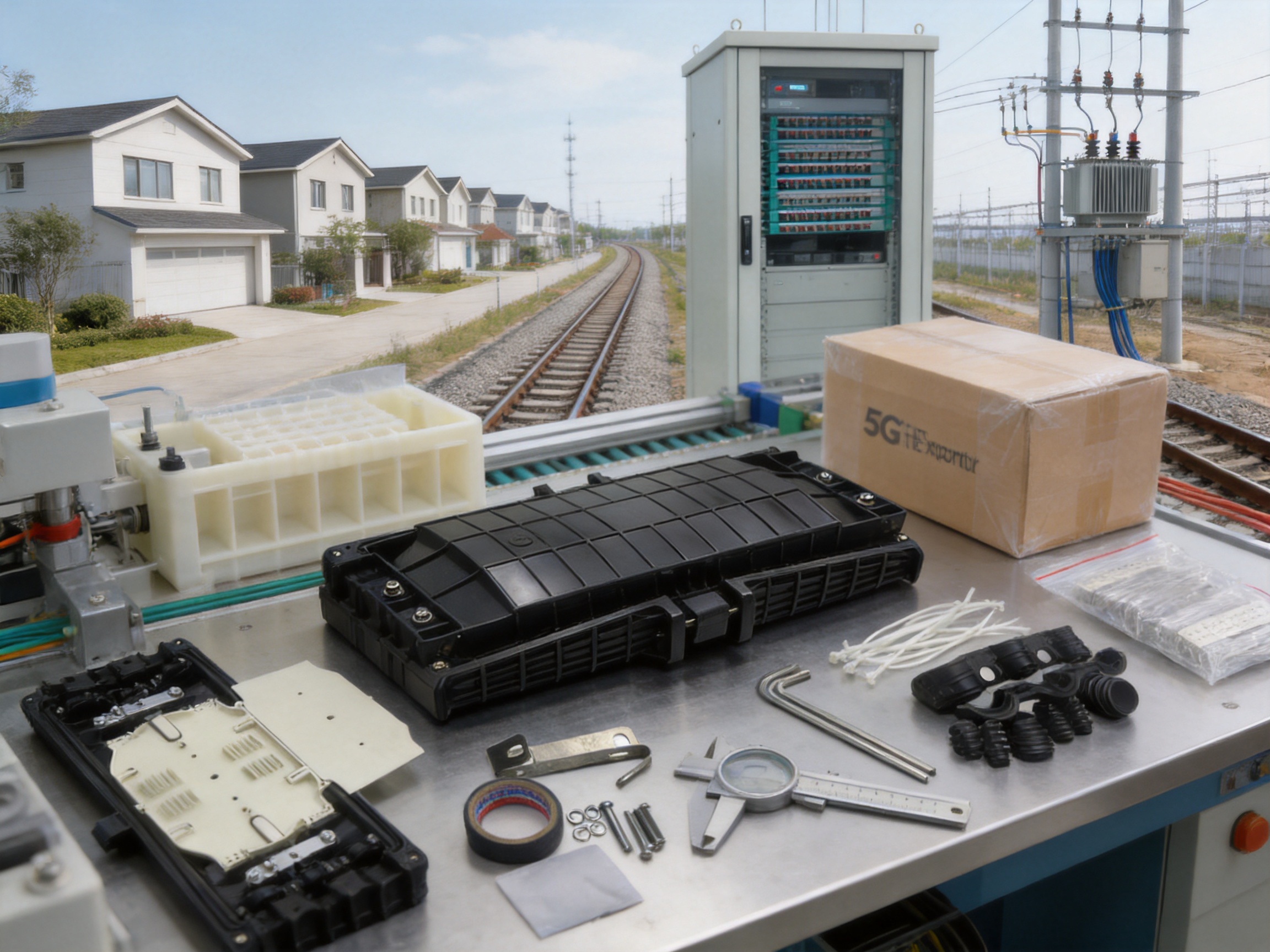
Network modernization requires scalable passive infrastructure. As traffic increases and access networks expand, operators need more fiber routes and more connection points. The WM-2001-H10 can support this growth by providing a structured location for fiber splicing and branching.
In FTTH networks, a distribution cable may serve several neighborhoods, buildings, or street cabinets. A splice closure can divide the cable route while protecting the optical connections from outdoor conditions. Its multiple trays can help organize customer groups or feeder segments, making future activation and fault repair easier.
In 5G transport infrastructure, fiber may connect radio sites with aggregation and core network equipment. The closure can be used at passive junctions along this route when the project’s environmental and mechanical requirements are satisfied. The use of a compact, protected closure can assist deployments where space is limited and the network must be expanded in stages.
Modernization projects also benefit from standardized products. Using a consistent closure model across similar access points can simplify technician training, spare-parts management, installation documentation, and maintenance procedures. Standardization does not eliminate the need for engineering review, but it can reduce unnecessary variation in the field.
Frequently Asked Questions
What is the primary purpose of the WM-2001-H10?
The primary purpose is to protect, organize, and distribute fiber optic splices between two or more cables. It is intended for user access points and outdoor communication infrastructure, including underground and aerial installations.
How many fibers can the closure accommodate?
The stated maximum capacity is 144 cores. The closure includes six splice trays, and each tray has a capacity of 24 cores.
Is the closure suitable for outdoor installation?
Yes. The product is designed for underground and aerial applications and is specified with an IP68 protection level. Correct installation, cable preparation, sealing, mounting, and maintenance are necessary to achieve the intended protection.
What material is used for the housing?
The housing is made from PP+GF, meaning glass-fiber-reinforced polypropylene. This material is selected to provide a combination of strength, low weight, and suitability for technical enclosure manufacturing.
How many cable ports are provided?
The closure has three inlet ports and three outlet ports. The listed cable port sizes are 16 mm, 20 mm, and 23 mm for both inlet and outlet positions.
What sealing method is used?
The stated sealing method for the cable inlets is screw mechanical sealing. The screws and sealing components should be installed and tightened according to the supplied instructions.
Can the product be used for FTTH networks?
It can be considered for suitable FTTH distribution and access applications. The final selection should be based on the network architecture, fiber count, cable dimensions, environmental conditions, and applicable local requirements.
Can it be used in railway or urban transit projects?
The manufacturer has experience serving high-speed railway and urban rail transit systems, and the closure may be suitable for selected passive optical connection points. Project engineers must verify all applicable railway, fire, environmental, vibration, and installation requirements before approval.
Does the closure include six splice trays?
Yes. The product description states that it is equipped with six splice trays, each supporting up to 24 cores.
What are the product dimensions?
The stated dimensions are approximately 395 × 190 × 110 mm.
Why is fiber routing important inside a splice closure?
Correct fiber routing helps preserve the fiber’s required bend radius, prevents excessive mechanical stress, and leaves enough slack for testing and future maintenance. Organized routing also makes fiber identification and troubleshooting easier.
Is the closure completely maintenance-free after installation?
No enclosure should be considered completely maintenance-free. The closure is designed to reduce environmental and mechanical risks, but the network owner should conduct inspections appropriate to the site. Any re-entry should be performed in a clean environment with careful attention to seals, fibers, labels, and fasteners.
What should buyers confirm before placing an order?
Buyers should confirm the required fiber capacity, cable diameters, number of cable routes, installation method, environmental conditions, mounting accessories, packaging requirements, delivery schedule, and any project-specific compliance documents.
Conclusion
The WM-2001-H10 Fiber Optic Splice Closure is a practical solution for protecting and organizing fiber connections in outdoor communication networks. Its principal strengths include a 144-core capacity, six 24-core splice trays, three inlet and three outlet ports, flexible cable port sizes, PP+GF construction, IP68 protection, screw mechanical sealing, and an internal routing design intended to preserve fiber curvature and provide storage space.
Compared with a basic low-capacity enclosure, it offers greater room for fiber distribution, improved separation of splice groups, and more flexible cable branching. Compared with a large cabinet-style solution, it provides a more compact approach for access points where substantial but not centralized capacity is required.
The product is relevant to Ethernet optical networks, cable television systems, FTTH and 5G modernization programs, and selected railway and urban transit communication installations. Its suitability for any particular project must be confirmed through engineering review and installation planning.
Manufacturing capability is an important part of the product’s value. The supplier’s long-term experience in communication cabinets, electronic communication equipment, passive optical components, Ethernet networks, optical communication networks, railway infrastructure, and urban rail transit supports an understanding of the demands placed on field-deployed network equipment. Controlled material selection, plastic molding, component assembly, inspection, and protective packaging all contribute to consistent product delivery.
For network operators, contractors, distributors, and system integrators seeking a durable and organized splice platform, the WM-2001-H10 provides a balanced combination of capacity, environmental protection, installation flexibility, and serviceability. When correctly selected and installed, it can help create dependable passive optical infrastructure for both current network requirements and future expansion.
References
1. Product technical information for the WM-2001-H10 Fiber Optic Splice Closure, including capacity, material, dimensions, cable ports, sealing method, and protection level.
2. Product overview and application information for outdoor fiber optic splice closures used in communication systems, cable television networks, and optical cable networks.
3. General principles of fiber optic cable installation, splice protection, bend-radius control, fiber routing, and optical maintenance.
4. General guidance on ingress protection classifications for electrical and communication equipment enclosures.
5. Manufacturer profile and company information concerning communication cabinets, communication electronic equipment, passive optical components, Ethernet networks, optical communication networks, railway systems, and urban rail transit applications.
6. General engineering practices for FTTH, 5G transport, Ethernet optical networks, and outdoor passive communication infrastructure.
Product: WM-2001-H10 Fiber Optic Splice Closure
PREV:Primary and Secondary Integrated Outdoor High-Voltage AC Vacuum Circuit Breaker
NEXT:Integrated Liquid-Cooled Cabinet: High-Density Infrastructure for Next-Generation Data Centers
NEXT:Integrated Liquid-Cooled Cabinet: High-Density Infrastructure for Next-Generation Data Centers
Interested in cooperation or have questions?
Related products
-
-
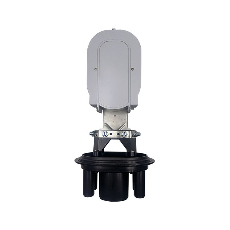
WM-2001-H11 type of It can be used to connect and branch fibers in aerial locations applications. The case body is made from high-intensity engineering plastics and shaped by mould injection under hig...
See Details -
WM-2001-H09 type of It can be used to connect and branch fibers in aerial locations applications. The case body is made from high-intensity engineering plastics and shaped by mould injection under hig...
See Details -
Technical data 1. Comply with various technical data of YD/T814.1-20132. Cable port: 103. Cable Diameter: φ7-φ204. Max Capacity: 288 single tray=48fibers5. Sealing way: silicone rubber6. Dimension: 4...
See Details
Ready to Get started ? Contact Us Now !

Product.
Contact Details.
-
 +86 13958188250
-
 +86 13958188250
-
 [email protected]
-
 AUDIT Email:[email protected]
- Wanma Industrial Park Taihu Yuan Town Lin'an District Hangzhou City China.
QR Code

Copyright © Wanma Technology Co., Ltd. All Rights Reserved.
Privacy
Custom Ethernet Optical Network Railway Transit Equipments Suppliers
