

 English
 Français
 Español
 Português
 عربى







OverviewModel No. JR-2001-H10 is one of the main equipment for user access points, applied for protective connection and distribution between two or more cables. The primary function is to connect dis...
See DetailsFiber Optic Splice Closure for Reliable FTTH, FTTB, and Railway Communication Networks
Content
- 1 1. The Role of a Fiber Optic Splice Closure
- 2 2. Product Overview
- 3 3. Protection Against Environmental Exposure
- 4 4. Mechanical Strength for Field Conditions
- 5 5. Electrical Insulation and Safety Considerations
- 6 6. High-Density Fiber Management
- 7 7. Installation Flexibility
- 8 8. Sealing and Reusability as Lifecycle Advantages
- 9 9. Product Advantages Compared with Basic Competing Designs
- 10 10. Manufacturing Strengths and Quality-Oriented Production
- 11 11. Application in FTTH and FTTB Networks
- 12 12. Application in Railway and Urban Transit Communication
- 13 13. Installation Procedure and Best Practices
- 14 14. Maintenance and Long-Term Reliability
- 15 15. Accessories Included with the Product
- 16 16. Company Manufacturing and Supply Capabilities
- 17 17. Selection Guidance for Network Operators and Contractors
- 18 18. Why the WM-2001-D10 Supports Network Modernization
- 19 19. Frequently Asked Questions
- 19.1 What is the WM-2001-D10 Fiber Optic Splice Closure used for?
- 19.2 How many fibers can the closure accommodate?
- 19.3 What cable diameter does the closure support?
- 19.4 Can the closure be installed underground?
- 19.5 Can it be mounted on a wall?
- 19.6 Can it be used in aerial networks?
- 19.7 What sealing materials are used?
- 19.8 What is its operating temperature range?
- 19.9 What does IP68 mean for this product?
- 19.10 Is the closure reusable?
- 19.11 What material is used for the shell?
- 19.12 What accessories are included?
- 19.13 Is the closure suitable for railway communication networks?
- 19.14 What should customers verify before purchasing?
- 19.15 Who manufactures the product?
- 20 20. Conclusion
- 21 References
- 22 Product: WM-2001-D10 Fiber Optic Splice Closure
Modern communication networks depend on physical infrastructure that is often hidden from view but essential to service reliability. Fiber cables may carry broadband access, enterprise data, railway signaling information, security video, industrial control traffic, and mobile network backhaul. Although optical fiber itself provides excellent bandwidth and long-distance transmission performance, exposed cable joints and splice points remain vulnerable areas. Moisture, dust, mechanical stress, temperature variation, accidental impact, and poor installation practices can all damage a splice and interrupt network service.
The WM-2001-D10 Fiber Optic Splice Closure is designed to protect optical fiber splices in a broad range of passive optical communication networks. Its applications include straight-through splicing, branching, and connection work in FTTH and FTTB systems, as well as communication infrastructure used in demanding commercial, industrial, transportation, and outdoor environments. The closure combines a high-strength synthetic plastic shell, silicone rubber sealing, heat-shrinkable sealing components, reusable construction, and several installation options.
Its design addresses the practical concerns faced by network operators and installation contractors: reliable protection, sufficient internal capacity, convenient access, adaptable mounting, resistance to environmental exposure, and controlled installation cost. With a maximum stated capacity of up to 288 single fibers, the closure can support network expansion while helping installers organize fiber splicing in a compact enclosure.
1. The Role of a Fiber Optic Splice Closure
A fiber optic splice closure is a protective enclosure installed where optical cables are joined, distributed, or redirected. Inside the enclosure, stripped fibers are routed to splice trays or other fiber management components, and individual fibers are joined using fusion splicing or another approved splicing method. The closure must then protect the splice area from water, dust, tension, bending, impact, and other external conditions.
The enclosure is not merely a box around the splice. It is part of the network reliability system. Its shell must withstand mechanical forces, its sealing system must prevent environmental intrusion, and its internal arrangement must allow fibers to be stored without exceeding their minimum bend radius. It must also be accessible for maintenance and capable of being re-entered when a network branch, replacement cable, or additional subscriber connection is required.
In FTTH networks, closures are commonly installed near distribution points, access routes, feeder cables, and branch connections. FTTB networks may use them at building entrances, underground access points, or outdoor distribution locations. In railway and urban transit applications, closures may support communication links along lines, in equipment zones, near stations, or in wayside infrastructure. These environments can expose equipment to vibration, temperature changes, dust, moisture, and occasional mechanical impact.
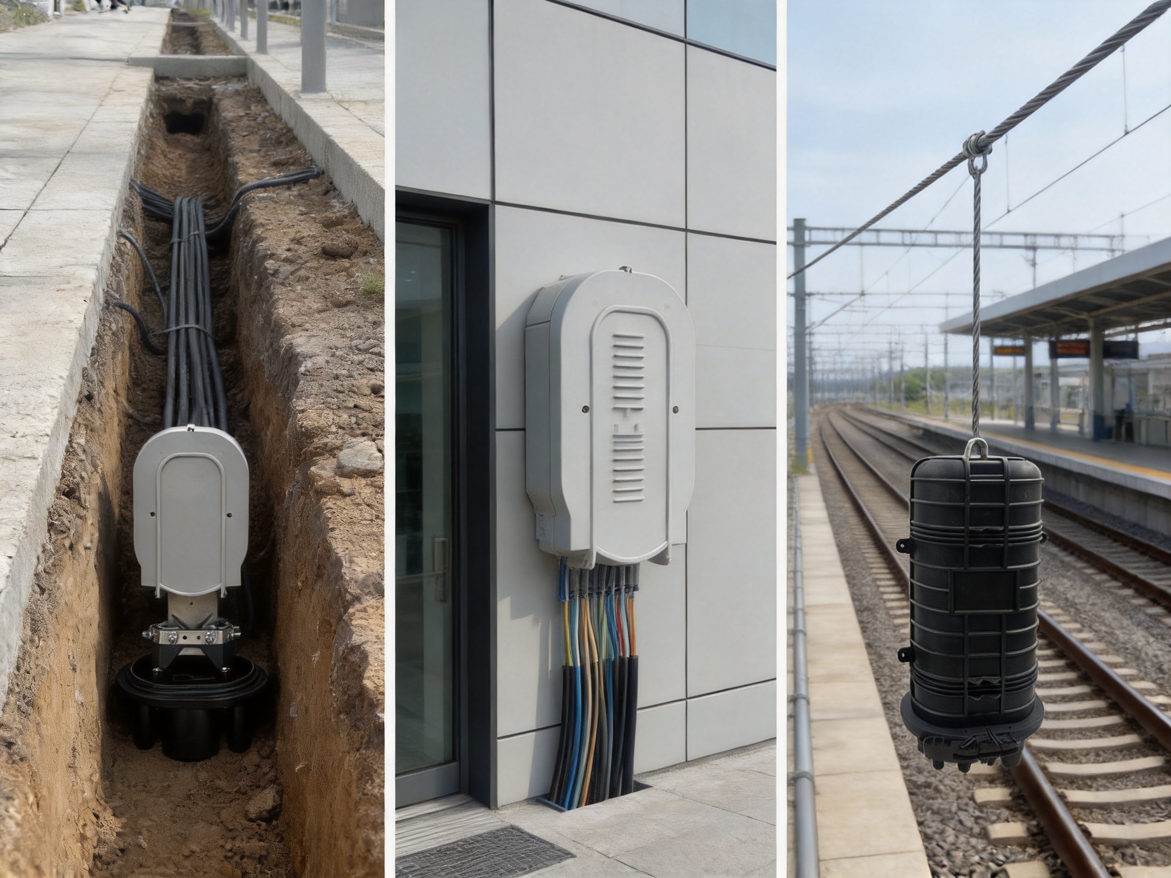
The WM-2001-D10 is intended to meet these needs through a sealed, reusable structure that can be directly buried, wall-mounted, or suspended from an aerial support wire. This flexibility allows the same basic product platform to be used across multiple deployment conditions instead of requiring a separate enclosure design for every installation method.
2. Product Overview
The WM-2001-D10 Fiber Optic Splice Closure is a compact horizontal fiber optic closure for passive optical communication networks. It is manufactured with high-strength PP synthetic plastic and has a shell thickness of at least 4 millimeters. The material and shell construction are intended to provide mechanical protection, insulation, heat resistance, corrosion resistance, aging resistance, flame resistance, and long service life.
The closure supports straight-through, diverging, and connection applications. In a straight-through application, incoming and outgoing cables are joined while preserving the continuity of the main route. In a diverging application, selected fibers can be directed toward a branch cable. In a connection application, the enclosure can support the relationship between feeder, distribution, and access cables in an optical network.
Its sealing system uses silicone rubber, together with heat-shrinkable sealing components and sticky sealing material. These elements work together to maintain a protective barrier around cable entries and the enclosure body. The product is also designed to be opened and reused, which is valuable when a network needs expansion, repair, inspection, or reconfiguration.
The stated working life is 25 years, while the specified environmental temperature range is from -40 degrees Celsius to +60 degrees Celsius. The closure also carries an IP68 protection rating. In practical terms, this rating indicates a high level of protection against dust and water ingress when the product is correctly assembled and installed according to the relevant instructions.
| Parameter | Stated Product Information | Practical Significance |
|---|---|---|
| Product type | Horizontal fiber optic splice closure | Protects and organizes optical fiber splice points |
| Application | FTTH, FTTB, and passive optical communication networks | Suitable for access, distribution, and branch networks |
| Material | High-strength PP synthetic plastic | Supports mechanical protection, insulation, and corrosion resistance |
| Shell thickness | At least 4 mm | Provides a substantial protective enclosure wall |
| Maximum capacity | Up to 288 single fibers | Supports high-density splicing and future expansion |
| Sealing method | Silicone rubber, heat-shrinkable seal, and sticky sealing material | Helps protect the splice area from environmental exposure |
| Working life | 25 years | Supports long-term infrastructure planning |
| Operating temperature | -40 degrees Celsius to +60 degrees Celsius | Suitable for a broad range of outdoor climates |
| Protection rating | IP68 | High resistance to dust and water ingress when correctly installed |
| Installation options | Directly buried, wall-mounted, and aerial-hung | Enables flexible deployment across different sites |
| Approximate dimensions | 470 x 230 mm | Provides a compact footprint for access and distribution locations |
| Approximate weight | 2.5 kg | Supports practical handling during installation |
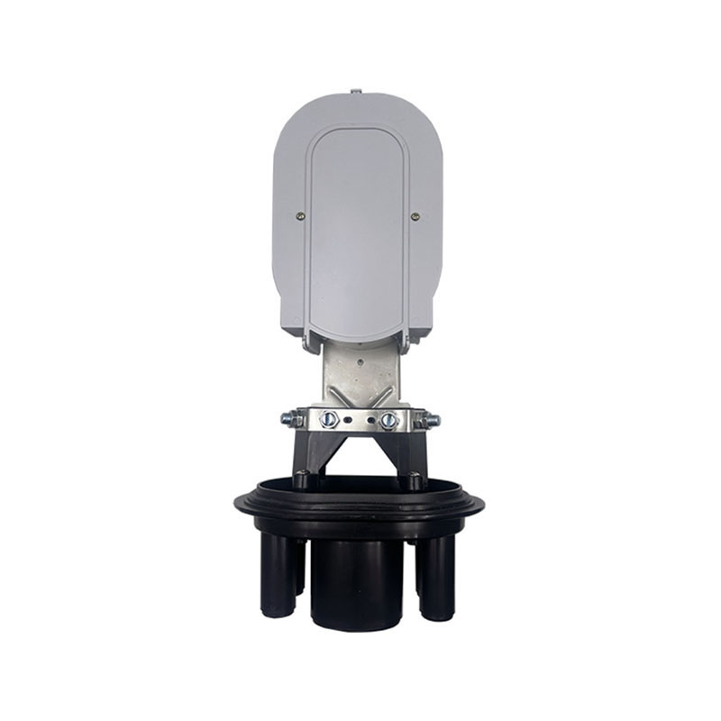
WM-2001-D10 Fiber Optic Splice Closure
3. Protection Against Environmental Exposure
The most important function of a splice closure is to keep the optical splice environment stable. A fiber splice may be technically excellent when completed, but it can deteriorate if moisture reaches the splice protector or if repeated temperature cycles cause condensation and material movement. The WM-2001-D10 addresses this risk through a multi-element sealing approach.
Silicone rubber is used as a sealing material because it can maintain flexibility over a broad temperature range. Flexible sealing materials can accommodate small changes in cable position and thermal expansion more effectively than rigid materials alone. When combined with heat-shrinkable components, the system can create a close fit around cable entry points and reduce possible paths for moisture or contaminants.
The closure is specified for an environmental temperature range of -40 degrees Celsius to +60 degrees Celsius. This range covers many outdoor network conditions, from cold winter installations to hot summer enclosures exposed to solar radiation. Temperature performance is especially important for buried, wall-mounted, and aerial installations because each location has different heating and cooling characteristics.
The IP68 rating is another significant advantage for outdoor deployment. Dust can accumulate inside poorly protected enclosures, while water can enter through cable ports, joints, or damaged seals. A high ingress protection rating helps reduce these risks. However, the rating depends on correct preparation, correct cable diameter selection, proper tightening or sealing, and careful installation. Even a well-designed closure requires trained workmanship to achieve its intended performance.
The stated sealing performance includes an inflation pressure of 70 to 106 kilopascals. This indicates that the enclosure design can be evaluated through pressure-based sealing tests. Pressure testing provides a practical way to identify leakage paths before a closure is placed into service, helping installers verify the condition of a completed assembly.
4. Mechanical Strength for Field Conditions
Outdoor communication equipment can be exposed to forces that do not appear in a laboratory drawing. Cable tension may be created during pulling, suspension, settlement, or accidental movement. Buried closures can experience soil pressure and localized loading. Aerial closures may be affected by wind, vibration, and cable movement. Wall-mounted closures can experience impact during nearby construction or maintenance activity.
The WM-2001-D10 includes stated mechanical performance values for tension, compression-related loading, impact, bending, and torsion. The product information lists a tension test of 800 newtons for one minute and a loading test of 2,000 newtons for 100 minutes. It also specifies an impact test involving a 1-meter drop of a 1.6-kilogram steel ball, applied three times. These tests are intended to evaluate whether the closure can resist representative mechanical stresses without losing its protective function.
The stated bending test uses 150 newtons, a plus-or-minus 45-degree movement, and 10 cycles. The torsion test uses 50 newton-meters, a 90-degree condition, and 10 cycles. Together, these tests address different types of movement that can occur when cables shift, when supports move, or when installation forces are transferred to the enclosure.
These specifications are particularly relevant to network operators who need closures to remain dependable after installation rather than only during initial commissioning. A closure that retains its shape, sealing performance, and internal fiber organization after mechanical stress can reduce the likelihood of repeated maintenance visits.
Compared with lightweight enclosures that prioritize minimum material usage, a shell thickness of at least 4 millimeters provides a more substantial physical barrier. The high-strength PP construction also offers a practical balance between rigidity and manageable weight. At approximately 2.5 kilograms, the closure remains suitable for field handling while providing a robust enclosure for a high-capacity splice area.
5. Electrical Insulation and Safety Considerations
Optical fibers do not carry electrical signals in the same way as copper conductors, but communication infrastructure can still be exposed to electrical hazards, induced voltages, grounding differences, and nearby power equipment. The enclosure material and internal protection system therefore need suitable insulation characteristics.
The product data lists an insulation resistance of 2 x 10^4 megohms at 500 volts and a compression strength test of 15 kilovolts for one minute at 10 milliamperes. These values indicate that the closure has been evaluated for electrical insulation and resistance under specified test conditions. Such performance can be important in outdoor cabinets, railway communication corridors, industrial sites, and locations where communication cables share infrastructure with electrical systems.
Nonconductive synthetic plastic also helps reduce corrosion concerns compared with metallic housings that may require additional surface treatment. The PP shell is not dependent on paint alone for its basic resistance to rust. This can be advantageous in humid, coastal, industrial, or chemically active environments where damaged coatings can expose metal to corrosion.
Electrical and grounding requirements vary by network design and local regulations. Installers should follow the applicable engineering standards and project requirements rather than treating the enclosure specification as a replacement for a complete site safety plan.
6. High-Density Fiber Management
Fiber capacity is a major consideration when selecting a splice closure. An enclosure that is adequate for a small initial deployment may become unsuitable when more subscribers, buildings, or network branches are added. The WM-2001-D10 has a stated maximum capacity of up to 288 single fibers, allowing it to support substantial fiber counts in a relatively compact form.
High capacity is useful in feeder and distribution networks where multiple fibers must be routed, stored, and protected. It can also reduce the number of separate closures required along a cable route. Fewer enclosures may simplify route planning, reduce the number of potential maintenance points, and make asset records easier to manage.
Capacity alone does not determine the quality of a splice closure. Internal organization is equally important. Fibers should be routed with adequate bend control, splice protectors should remain secure, and slack fiber should be stored without sharp bends or compression. A high-capacity closure must provide enough usable space for orderly installation rather than simply allowing a large number of fibers to be forced into a limited compartment.
The horizontal format supports organized access to the internal splice area. During maintenance, technicians can inspect the splice arrangement, identify cable routes, and work on selected fibers without unnecessarily disturbing the entire cable system. This is valuable in live networks, where every additional movement can increase the risk of accidental damage.
The reusable design further improves long-term value. Networks rarely remain unchanged for 25 years. Subscriber numbers increase, distribution architectures evolve, and new services are introduced. A closure that can be reopened and expanded may offer a lower lifecycle cost than a permanently sealed unit that must be replaced whenever the network changes.
7. Installation Flexibility
Different network routes require different mounting methods. A closure installed beneath a sidewalk may need direct burial. A closure in a building entrance may require wall mounting. A closure along an overhead route may need an aerial hanger. The WM-2001-D10 supports all three approaches.
Direct Burial Installation
For direct burial, the closure can be placed underground after the sealing process has been completed and verified. This method can preserve a clean surface appearance and protect the closure from direct sunlight, accidental contact, and certain forms of vandalism. Before burial, installers should verify cable routing, sealing condition, pressure performance, and the protection of cable entries.
Buried installations should also consider drainage, soil conditions, mechanical loading, and future access. A closure may have strong water resistance, but the surrounding installation still needs to prevent crushing, uncontrolled settlement, or damage from later excavation. Suitable marking and route documentation are important for future maintenance teams.
Wall-Mounted Installation
For wall mounting, the product can be fixed using a hanging hook or suitable mounting arrangement. Wall mounting is useful in equipment rooms, building service areas, utility corridors, and outdoor walls. It makes the closure easier to inspect than a buried unit and may simplify future branch connections.
The wall surface should be structurally suitable, and the cable route should not impose excessive tension on the enclosure. The closure should be positioned so that technicians have enough room to open it, route cables, and perform testing. Avoiding direct exposure to unnecessary mechanical hazards can further extend service reliability.
Aerial-Hung Installation
For aerial deployment, the closure can be suspended from a steel wire using the appropriate hanging hook. This method is useful where cables are supported above roads, rail corridors, industrial yards, or rural routes. The support system should carry the mechanical load and prevent the closure from hanging directly from delicate fiber components.
Aerial installations should account for wind movement, vibration, ice or snow where applicable, cable sag, and clearance requirements. Proper strain management is essential. The closure itself may withstand specified tension and torsion tests, but the full installation must still be engineered as a complete cable-support system.
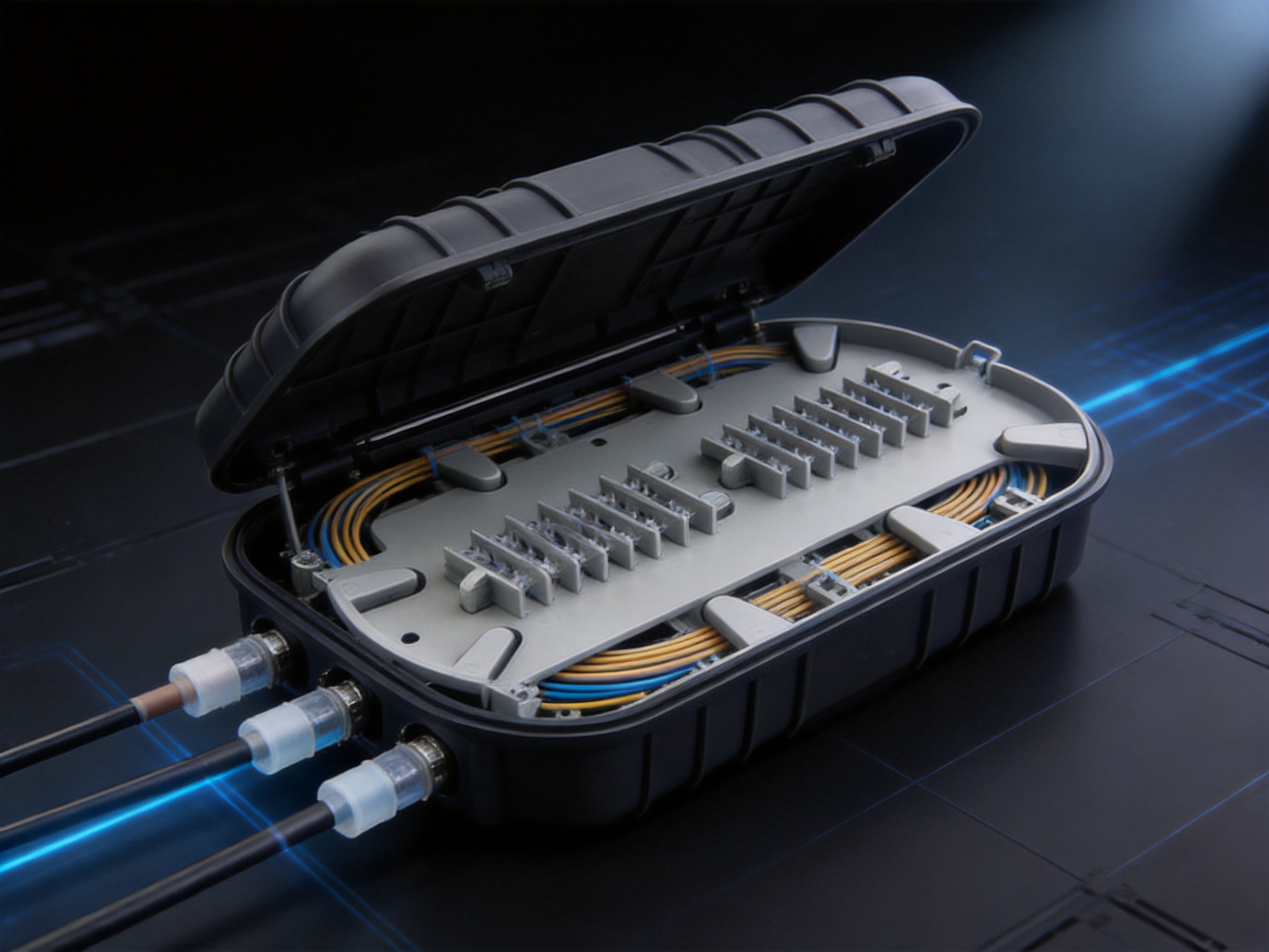
8. Sealing and Reusability as Lifecycle Advantages
One of the product's practical advantages is the combination of sealing performance and reusability. Some low-cost closures are designed primarily for one-time installation. They may provide acceptable protection for a fixed configuration but become difficult to access when a new branch or repair is required. A reusable closure is better suited to networks that will grow over time.
The WM-2001-D10 uses a sealing structure that incorporates silicone rubber, heat-shrinkable sealing components, and sticky sealing material. These components can be prepared during installation to match the cable arrangement. When the closure is correctly assembled, the sealing system helps isolate the splice area from water, dust, and other external contaminants.
Reusability supports several maintenance activities. Technicians may reopen the closure to inspect a suspected splice problem, add a distribution cable, replace a damaged cable section, reorganize fiber routing, or expand the network. The ability to work with the existing enclosure can reduce material waste and avoid the labor associated with replacing an entire closure.
Reusable construction also helps operators standardize their spare-parts strategy. Instead of stocking several types of single-purpose closures, an operator may use a flexible product platform for multiple routes and installation styles. Standardization can simplify training, inventory control, field procedures, and quality audits.
9. Product Advantages Compared with Basic Competing Designs
Product selection should be based on project requirements, applicable standards, and verified test documentation. Within that framework, the WM-2001-D10 offers several characteristics that can distinguish it from basic or less adaptable closure designs.
Broad Application Coverage
The closure is designed for straight-through, diverging, and connection applications. This means that the same product family can support multiple points in an optical distribution architecture. A basic enclosure intended only for straight-through splicing may require a different product when branches or additional connections are introduced. The WM-2001-D10 is positioned as a more versatile option for evolving network layouts.
High Fiber Capacity
With a stated capacity of up to 288 single fibers, the closure can accommodate higher-density applications than small closures intended for limited subscriber counts. High capacity can reduce the number of enclosure locations and create room for network growth. It is particularly useful where feeder and distribution cables converge at a common point.
Multiple Installation Methods
Direct burial, wall mounting, and aerial hanging provide flexibility across urban, rural, industrial, and transportation projects. A competing enclosure may be optimized for only one mounting method, requiring additional brackets or a separate product for another environment. A multi-installation design can reduce procurement complexity and support more consistent field practices.
Durable Nonmetallic Shell
The high-strength PP shell offers insulation and corrosion resistance while maintaining manageable weight. In environments where rust, humidity, salt exposure, or chemical contamination are concerns, a nonmetallic enclosure can reduce dependence on protective coatings. A shell thickness of at least 4 millimeters also supports a stronger physical structure than ultra-thin housings.
Long-Term Service Planning
A stated 25-year working life supports long-term network planning. While actual service life depends on installation quality, exposure, maintenance, and system conditions, a long-life design can help operators evaluate total cost of ownership rather than focusing only on initial purchase price.
High Ingress Protection
The IP68 rating and pressure-based sealing performance are important for outdoor and buried deployments. Protection against dust and water helps limit environmental degradation at the splice point. This feature can be especially valuable in locations where access is difficult and a failure would require traffic control, excavation, or specialized maintenance equipment.
10. Manufacturing Strengths and Quality-Oriented Production
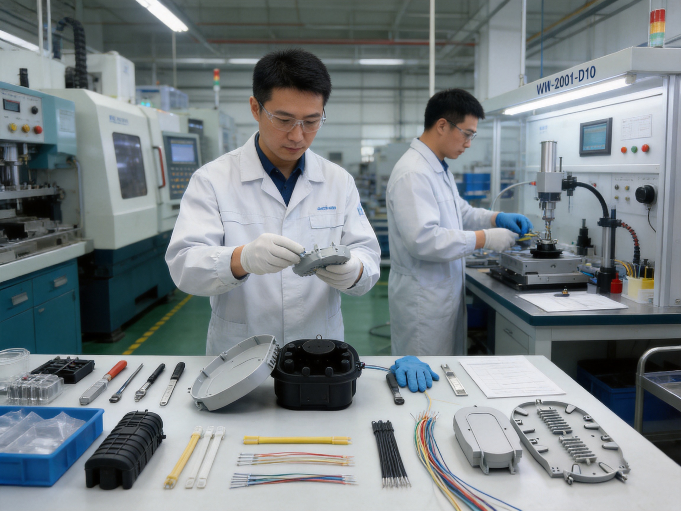
Wanma Technology Co., Ltd. was established in 1997 and specializes in communication cabinets, communication electronic equipment, and passive optical components. Its product portfolio is used in Ethernet networks, optical communication networks, central equipment rooms, high-speed railway systems, and urban rail transit infrastructure. This industry experience provides an important manufacturing foundation for products such as the WM-2001-D10.
Manufacturing a dependable splice closure requires more than molding a plastic shell. The final product depends on material selection, mold accuracy, dimensional control, sealing preparation, accessory matching, assembly discipline, and inspection. A weakness in any of these areas can affect field performance. Long-term experience in communication equipment allows a manufacturer to understand how enclosure design interacts with cable routing, optical components, rack systems, and network construction methods.
Material and Shell Processing
The high-strength PP shell must be produced with consistent wall thickness, stable dimensions, and suitable surface quality. A shell thickness of at least 4 millimeters requires controlled molding conditions and careful attention to cooling and shrinkage. Dimensional variation can affect the fit of seals, cable ports, hooks, and internal components.
Modern plastic processing also requires attention to material handling. Resin must be stored and processed under controlled conditions, while molding parameters need to remain within an approved production window. Temperature, pressure, injection speed, holding time, and cooling time can all influence the strength and dimensional stability of the finished part.
For a closure exposed to outdoor conditions, material performance must be evaluated beyond initial appearance. Resistance to aging, heat, corrosion-related exposure, and flame behavior should be considered during product development and quality control. Consistency from batch to batch is essential because network operators need the same installation experience across large projects.
Sealing Component Integration
Sealing is a system function rather than a single component. The body, cable ports, silicone rubber elements, heat-shrinkable parts, and sticky sealing materials must work together. Manufacturing quality therefore includes not only component production but also compatibility control and assembly guidance.
Sealing components must be supplied in appropriate dimensions and quantities. Heat-shrinkable tubes must be free from damage and suitable for the specified cable range. Rubber elements must retain elasticity and be protected from contamination before installation. Accessories must be packed so they remain identifiable and usable in the field.
Production teams can support reliability by applying incoming material inspection, first-piece approval, process inspection, and final assembly checks. These controls help reduce the possibility of missing components, incorrect parts, surface damage, or inconsistent closure fit.
Mechanical and Environmental Verification
The product data includes performance testing for tension, impact, bending, torsion, pressure sealing, insulation resistance, compression strength, and environmental temperature. A capable manufacturer can use these tests not only for product certification but also for design improvement and process monitoring.
Testing may be conducted on development samples, production samples, or units selected according to a quality plan. The objective is to verify that the enclosure continues to meet its intended requirements when exposed to representative stresses. For a product used in railway and outdoor infrastructure, mechanical and environmental verification is particularly important because field access may be costly and service interruption may have serious consequences.
Wanma Technology's experience with railway and urban transit communication environments gives it a practical understanding of infrastructure projects where product reliability, delivery coordination, documentation, and long-term support all matter. This background can be valuable for customers purchasing closures as part of a larger communication solution rather than as isolated components.
Integrated Product Development
The company develops, manufactures, and markets its own branded products while also providing integrated solutions for customized products. This capability can shorten communication between engineering, production, and customer service teams. When a customer requires a particular cable configuration, mounting arrangement, labeling approach, accessory package, or project documentation format, integrated development can make adaptation more efficient.
Customization should always be controlled through engineering review and product validation. The benefit of an experienced manufacturer is that customization can be evaluated against mechanical, sealing, optical, and environmental requirements instead of being treated as a purely cosmetic change.
11. Application in FTTH and FTTB Networks
Fiber-to-the-home networks must support large numbers of subscribers while remaining cost-effective and easy to maintain. Closures are installed at points where feeder fibers are connected to distribution cables, where branch cables serve neighborhoods, and where subscriber access routes are organized.
The WM-2001-D10 can support these functions by providing a protected and expandable splice location. Its high capacity is useful in areas where many fibers converge, while its reusable design permits later additions. The closure can be buried to preserve streetscape appearance, mounted on a wall near a building or distribution point, or suspended in an aerial route.
In FTTB applications, cables may enter building service areas, telecommunications rooms, or outdoor distribution cabinets. The closure's compact footprint and flexible mounting options can help installers position it near the cable transition point. Proper fiber routing remains essential, especially when cables from different floors, buildings, or service zones are brought together.
For network operators, the product can contribute to a standardized deployment model. A consistent closure platform simplifies technician training and helps reduce variation between projects. Standardized procedures can cover cable preparation, fiber storage, seal assembly, pressure testing, mounting, labeling, and inspection.
12. Application in Railway and Urban Transit Communication
Railway and urban transit systems use optical networks for operations, passenger information, surveillance, access control, signaling support, communications, and administrative data. These networks may extend over long routes and include equipment rooms, stations, tunnels, depots, trackside facilities, and control centers.
Splice closures used in these systems must withstand demanding installation conditions and provide dependable protection over long periods. A closure may be installed in a service corridor, buried near a route, mounted in a technical area, or suspended along an infrastructure pathway. The WM-2001-D10's multiple installation options make it adaptable to these different locations.
The mechanical test data is relevant to transit environments because vibration, movement, and accidental impact can affect cable infrastructure. Its temperature range and IP68 protection rating also support outdoor and semi-outdoor locations, subject to the complete system design and local environmental conditions.
Railway projects often require strong documentation, product consistency, delivery coordination, and traceability. Wanma Technology's involvement in communication equipment used in high-speed railway and urban rail transit systems supports its ability to participate in projects where passive optical components must align with a larger infrastructure program.
13. Installation Procedure and Best Practices
Site Preparation
Before installation, technicians should confirm the closure model, cable diameter, fiber count, mounting method, and accessory list. The work area should be clean and sufficiently illuminated. Fiber handling tools, splice equipment, cleaning materials, sealing tools, and personal protective equipment should be prepared in advance.
The cable route should be inspected for excessive tension, sharp edges, water accumulation, unstable supports, or other conditions that could transfer stress to the closure. For buried installation, the planned depth, soil condition, drainage, and future access should be reviewed. For wall or aerial installation, the support structure and clearance should be checked.
Cable Entry and Preparation
The product information specifies a cable diameter range of approximately 7 to 20 millimeters. The actual cable must be checked against the approved cable port and sealing components before work begins. Cable jackets should be stripped according to the installation instructions, and the strength member should be secured so that pulling forces do not reach the splice area.
Technicians should avoid nicking fibers or weakening the cable during preparation. The cable should be cleaned before sealing, and all cut surfaces should be free from loose particles. The cable entry area should be arranged so that the heat-shrinkable tube and sealing materials can be installed evenly.
Fiber Routing and Splicing
Fibers should be routed through the internal management system with controlled bend radius and adequate slack. Splice protectors should be positioned securely, and fiber identification should be maintained throughout the process. Each fiber should be tested according to the project requirements before the closure is finally sealed.
When a large number of fibers are installed, organized labeling becomes increasingly important. Clear records can reduce troubleshooting time and prevent technicians from disturbing unrelated fibers during future work. The high capacity of the WM-2001-D10 is most beneficial when its internal space is used systematically.
Sealing and Inspection
Silicone rubber, heat-shrinkable sealing components, and sticky sealing material should be installed in the specified sequence. Heat should be applied evenly and with suitable equipment. Excessive heat can damage cable jackets or nearby materials, while insufficient heat may prevent proper contraction and adhesion.
After sealing, the closure should be inspected for gaps, displaced components, damaged rubber, incomplete shrinkage, or contamination. Where the project requires it, an inflation pressure test can be performed within the stated range. Testing should be recorded as part of the installation documentation.
Mounting and Final Documentation
The closure should be mounted or buried only after sealing and inspection are complete. Cables should be supported so that the closure does not carry unintended tension. The installation location, cable identification, fiber allocation, test results, and date should be recorded.
Good documentation is particularly important for buried and railway installations. A closure that cannot be located quickly may create unnecessary excavation, service delays, and safety risks. Labels should remain readable, and route information should be stored in the operator's asset management system.
14. Maintenance and Long-Term Reliability
A splice closure is designed to reduce maintenance requirements, but it should not be ignored after installation. Periodic inspection may be appropriate for exposed wall-mounted and aerial units, especially in areas subject to construction, severe weather, vibration, or cable movement. Buried closures may be inspected when nearby work is performed or when optical test results indicate a problem.
Maintenance teams should look for signs of physical damage, displaced supports, exposed cable jackets, water accumulation, cracked sealing components, and unauthorized access. Any re-entry should follow a controlled procedure. The closure should be cleaned before opening, and fibers should be protected from dirt, excessive bending, and unnecessary movement.
The reusable design enables corrective maintenance and network expansion, but the sealing system should be restored carefully after every re-entry. Used sealing materials may need replacement, and all cable ports should be checked before the closure is returned to service. Repeated opening without proper resealing can compromise the original protection level.
Optical time-domain reflectometer testing, insertion-loss testing, and visual inspection can be used as part of a broader network maintenance program. If attenuation increases after environmental or mechanical stress, technicians can inspect the closure and splice area as part of fault isolation.
15. Accessories Included with the Product
The basic accessory package includes cable ties, heat-shrinkable tubes, PVC tubes, heat-shrinkable protection tubes, silver paper, and alcohol paper. These accessories support cable organization, protection, cleaning, and sealing during installation.
Cable ties help maintain order around cable and fiber management areas, although they should be applied carefully. Excessive tightening can deform cable jackets or place pressure on internal fibers. PVC tubes can provide additional separation or protection, while heat-shrinkable protection tubes help protect splice points after splicing.
Alcohol paper is used to clean relevant surfaces before sealing or splicing. Clean surfaces are important because dust, grease, and moisture can reduce adhesion and sealing quality. Silver paper is included as part of the basic accessory set and should be used according to the manufacturer's installation instructions.
Accessory completeness is a practical manufacturing strength. Missing or mismatched small parts can delay a field installation even when the main enclosure is available. An organized accessory package helps contractors prepare work efficiently and reduces the need to source compatible components separately.
16. Company Manufacturing and Supply Capabilities
Wanma Technology Co., Ltd. has operated in the communication equipment sector since 1997. Its experience covers communication cabinets, communication electronic equipment, passive optical components, Ethernet network equipment, optical communication network products, and equipment-room infrastructure. The company serves customers in more than 20 countries and regions, including markets in North America, Australia, the United Kingdom, Italy, South Africa, and Ghana.
This international sales coverage reflects experience with different project expectations, climate conditions, packaging requirements, technical documents, and delivery schedules. Customers evaluating a splice closure supplier often need more than a product datasheet. They may require predictable lead times, export coordination, consistent quality, technical communication, and support for repeat orders.
The company's manufacturing and marketing model combines its own branded products with integrated solutions for customized products. This can benefit customers developing network modernization programs, railway communication projects, 5G FTTH deployments, or multi-site optical infrastructure. Instead of treating the closure as an isolated commodity, the supplier can consider how it fits into cabinets, passive optical distribution systems, cable routes, and installation procedures.
Wanma Technology emphasizes reliable product quality, timely delivery, and long-term strategic partnerships. These priorities are important for infrastructure products because replacement and requalification can be expensive after a project has entered large-scale deployment. A stable supplier relationship can help customers maintain product continuity and technical consistency over several phases of network construction.
17. Selection Guidance for Network Operators and Contractors
Before ordering the WM-2001-D10, customers should confirm the required fiber count, cable diameter, cable type, splice protector dimensions, mounting method, environmental conditions, and local standards. The stated maximum capacity should be compared with the actual splice plan, including spare fibers and future expansion.
Customers should also determine whether the closure will be buried, wall-mounted, or aerially suspended. Each installation method creates different requirements for support, access, protection, and route documentation. The closure should be selected together with compatible cable entry seals and mounting accessories.
For large projects, a sample installation or pilot deployment can be valuable. A pilot allows technicians to confirm cable preparation lengths, internal routing, sealing time, pressure testing, mounting details, and documentation procedures. Lessons from the pilot can then be applied to the broader rollout.
Procurement teams should request current technical drawings, installation instructions, quality documents, packaging information, and test records where required. They should also confirm whether special labeling, accessory quantities, or customized packaging is needed. Early technical coordination helps prevent delays later in the project.
18. Why the WM-2001-D10 Supports Network Modernization
Network modernization is not limited to installing faster active equipment. It also requires dependable passive infrastructure that protects the physical fiber route. As broadband, 5G backhaul, railway digitalization, and intelligent transportation systems expand, more fiber cables are installed in locations where access and reliability are critical.
The WM-2001-D10 supports modernization by combining high fiber capacity, flexible installation, environmental sealing, mechanical protection, and reusability. These characteristics allow it to serve both initial deployment and later network growth. A closure that can accommodate future branches may reduce the need to disturb existing routes when demand increases.
Its use of high-strength PP synthetic plastic, insulation properties, corrosion resistance, and IP68 protection also makes it suitable for outdoor infrastructure where long-term environmental exposure must be considered. The product's test data provides a basis for engineering review, while the manufacturer's experience supports integration into broader communication equipment projects.
For customers seeking a balance between performance and lifecycle practicality, the closure offers a strong combination of physical protection and installation flexibility. It is not simply a protective shell; it is a reusable component for organizing and maintaining the access layer of a fiber network.
19. Frequently Asked Questions
What is the WM-2001-D10 Fiber Optic Splice Closure used for?
It is used to protect, organize, and seal optical fiber splices in FTTH, FTTB, and other passive optical communication networks. It supports straight-through, diverging, and connection applications.
How many fibers can the closure accommodate?
The stated maximum capacity is up to 288 single fibers. The actual usable capacity depends on the splice arrangement, fiber management components, cable type, and installation method.
What cable diameter does the closure support?
The product information specifies a cable diameter range of approximately 7 to 20 millimeters. Customers should confirm the exact cable entry configuration before placing an order.
Can the closure be installed underground?
Yes. It can be directly buried after the sealing and pressure checks have been completed. The surrounding burial environment should still be engineered to prevent crushing, uncontrolled settlement, and future access problems.
Can it be mounted on a wall?
Yes. A hanging hook can be used for wall-mounted installation when the mounting surface and support arrangement are suitable.
Can it be used in aerial networks?
Yes. The closure can be suspended from a steel wire with the appropriate hanging hook. Aerial installations must account for wind, vibration, cable tension, clearance, and support loading.
What sealing materials are used?
The closure uses silicone rubber as part of its sealing system and also includes heat-shrinkable sealing components and sticky sealing material. Correct preparation and installation are essential to achieve the intended protection level.
What is its operating temperature range?
The stated environmental temperature range is -40 degrees Celsius to +60 degrees Celsius.
What does IP68 mean for this product?
IP68 indicates a high level of protection against dust and water ingress under defined test conditions. The rating depends on proper assembly, sealing, cable selection, and installation quality.
Is the closure reusable?
Yes. The design is intended to be reopened and reused for network expansion, repair, inspection, and reconfiguration. Sealing components should be checked and replaced when necessary after re-entry.
What material is used for the shell?
The shell is made from high-strength PP synthetic plastic and has a stated thickness of at least 4 millimeters.
What accessories are included?
The basic accessories include cable ties, heat-shrinkable tubes, PVC tubes, heat-shrinkable protection tubes, silver paper, and alcohol paper.
Is the closure suitable for railway communication networks?
It can be considered for railway and urban transit optical communication applications when its specifications match the project requirements. Site conditions, applicable railway standards, installation procedures, and environmental tests should be reviewed by the project engineer.
What should customers verify before purchasing?
Customers should verify fiber capacity, cable diameter, installation method, environmental conditions, splice protector compatibility, required accessories, technical documentation, and applicable standards. A sample installation may be useful for large projects.
Who manufactures the product?
The WM-2001-D10 is manufactured and supplied by Wanma Technology Co., Ltd., a communication equipment company established in 1997 with experience in communication cabinets, electronic equipment, passive optical components, Ethernet networks, optical communication networks, railway systems, and urban rail transit infrastructure.
20. Conclusion
The WM-2001-D10 Fiber Optic Splice Closure is designed for network operators and contractors who need dependable protection for high-density optical fiber splicing. Its main strengths include a stated capacity of up to 288 single fibers, a high-strength PP shell with at least 4 millimeters of thickness, silicone rubber and heat-shrinkable sealing, a 25-year stated working life, a -40 degrees Celsius to +60 degrees Celsius temperature range, and an IP68 protection rating.
The closure's ability to support direct burial, wall mounting, and aerial hanging makes it adaptable to FTTH, FTTB, outdoor access, railway, urban transit, and other passive optical network environments. Its reusable design also supports network growth and maintenance, helping operators avoid unnecessary replacement when cable routes or subscriber requirements change.
Beyond the product itself, the manufacturer's experience in communication infrastructure, passive optical components, railway systems, and international supply provides an important foundation for project support. Controlled material processing, sealing component integration, mechanical testing, environmental verification, and integrated product development all contribute to a more reliable manufacturing process.
For customers building or modernizing optical networks, the WM-2001-D10 offers a practical combination of protection, capacity, installation flexibility, and lifecycle value. Proper engineering review and professional installation remain essential, but the product provides a strong platform for protecting the splice points that keep modern communication networks connected.
References
1. Product technical data and installation information for the WM-2001-D10 Fiber Optic Splice Closure.
2. YD/T 814.1, technical requirements for optical fiber cable connection and protection equipment.
3. IEC 60529, degrees of protection provided by enclosures, including ingress protection classifications.
4. General engineering practices for fiber optic cable preparation, fusion splicing, splice protection, and fiber bend-radius management.
5. International practices for passive optical network design, FTTH deployment, and outdoor communication infrastructure installation.
6. Manufacturer information concerning communication cabinets, communication electronic equipment, passive optical components, Ethernet networks, railway communication systems, and urban rail transit applications.
Product: WM-2001-D10 Fiber Optic Splice Closure
PREV:Fiber Solution Drop Cables: A Practical Foundation for Reliable FTTH Deployment
NEXT:WM-1001-F023 Fiber Optic Distribution Box: A Practical Platform for Outdoor FTTH Access Networks
NEXT:WM-1001-F023 Fiber Optic Distribution Box: A Practical Platform for Outdoor FTTH Access Networks
Interested in cooperation or have questions?
Related products
-
-
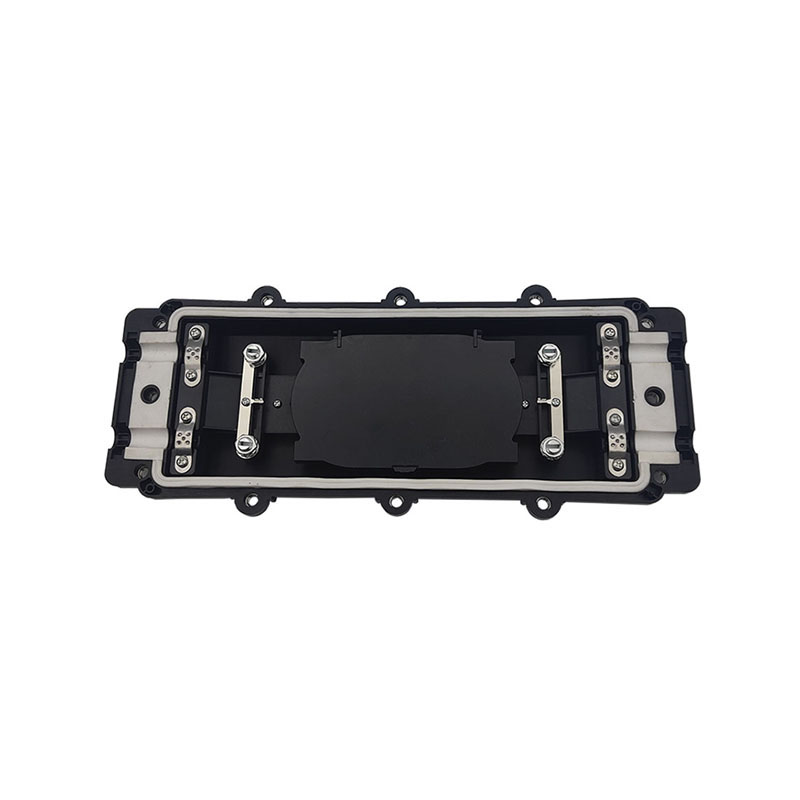
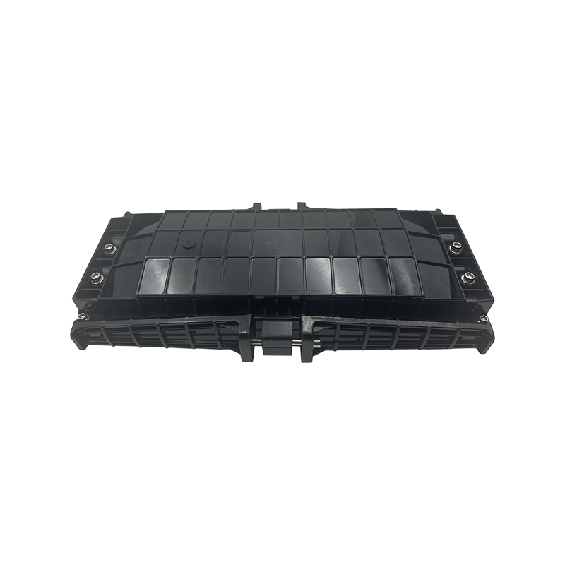
WM-2001-H09 type of It can be used to connect and branch fibers in aerial locations applications. The case body is made from high-intensity engineering plastics and shaped by mould injection under hig...
See Details -
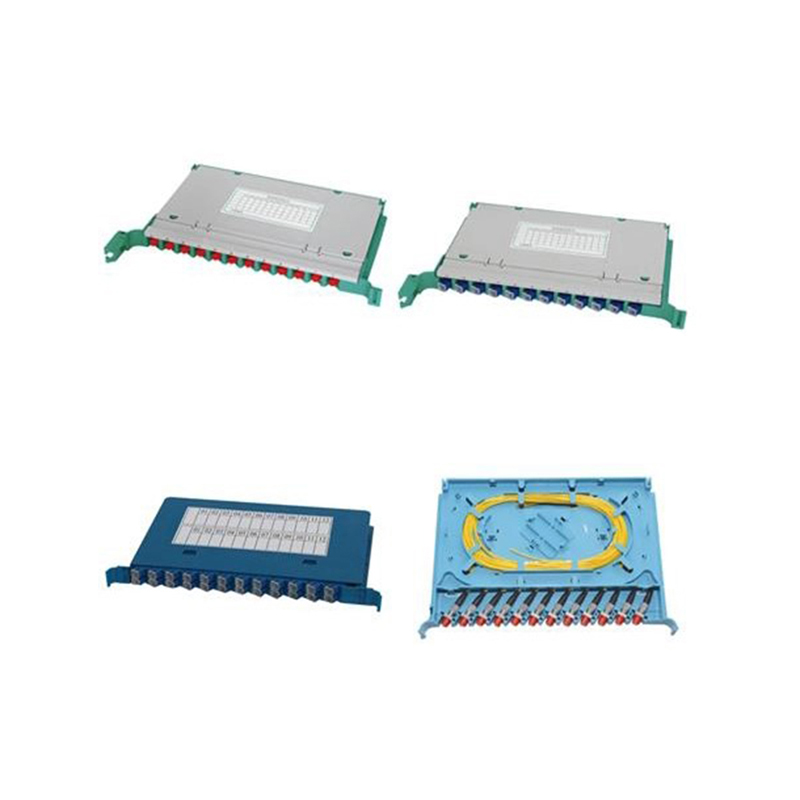
Application:It is extensively used as optical cable splicing and distribution unit in the OMDF, ODF, OCC and outdoor cabinet. Features:1. Splice Module can be used for fiber splicing, fiber distributi...
See Details -
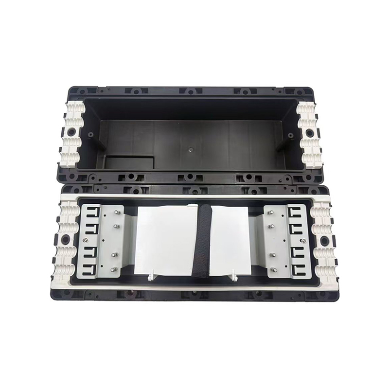
WM-2001-H11 type of It can be used to connect and branch fibers in aerial locations applications. The case body is made from high-intensity engineering plastics and shaped by mould injection under hig...
See Details
Ready to Get started ? Contact Us Now !

Product.
Contact Details.
-
 +86 13958188250
-
 +86 13958188250
-
 [email protected]
-
 AUDIT Email:[email protected]
- Wanma Industrial Park Taihu Yuan Town Lin'an District Hangzhou City China.
QR Code

Copyright © Wanma Technology Co., Ltd. All Rights Reserved.
Privacy
Custom Ethernet Optical Network Railway Transit Equipments Suppliers
