

 English
 Français
 Español
 Português
 عربى






Product Overview The WM-1001-F023 Fiber Optic Distribution Box is designed for fiber distribution, splicing and management in fiber access networks. It supports aerial mounting and provides 16 subscri...
See DetailsWM-1001-F023 Fiber Optic Distribution Box: A Practical Platform for Outdoor FTTH Access Networks
Content
- 1 1. The Role of Fiber Distribution Boxes in Access Networks
- 2 2. Product Overview
- 3 3. Enclosure Material and Outdoor Protection
- 4 4. Internal Structural Design
- 5 5. Fiber Capacity and Splicing Performance
- 6 6. Splitter and Adapter Compatibility
- 7 7. Subscriber Port Configuration
- 8 8. Installation and Deployment Applications
- 9 9. Advantages Compared with Conventional or Less Integrated Boxes
- 10 10. Manufacturing Strengths and Quality-Oriented Production
- 11 11. Technical Specification Summary
- 12 12. Installation Planning Considerations
- 13 13. Operational and Maintenance Benefits
- 14 14. Why the Product Is Suitable for Network Modernization
- 15 15. Company Capability and Industry Experience
- 16 16. Procurement Guidance for Project Owners
- 17 17. Frequently Asked Questions
- 17.1 17.1 What is the main purpose of the WM-1001-F023?
- 17.2 17.2 Is the box suitable for aerial installation?
- 17.3 17.3 How many subscriber connections can it support?
- 17.4 17.4 What is the maximum fiber capacity?
- 17.5 17.5 Which PLC splitters can be installed?
- 17.6 17.6 Which adapters are supported?
- 17.7 17.7 What cable diameters are supported at the inlet ports?
- 17.8 17.8 What environmental protection does the enclosure provide?
- 17.9 17.9 What temperature range is supported?
- 17.10 17.10 What is the enclosure material?
- 17.11 17.11 Does the product support future network expansion?
- 17.12 17.12 What accessories are included?
- 17.13 17.13 Which standards and compliance requirements are identified?
- 17.14 17.14 Who can benefit from this product?
- 18 18. Conclusion
- 19 References
- 20 Product: WM-1001-F023 Fiber Optic Distribution Box
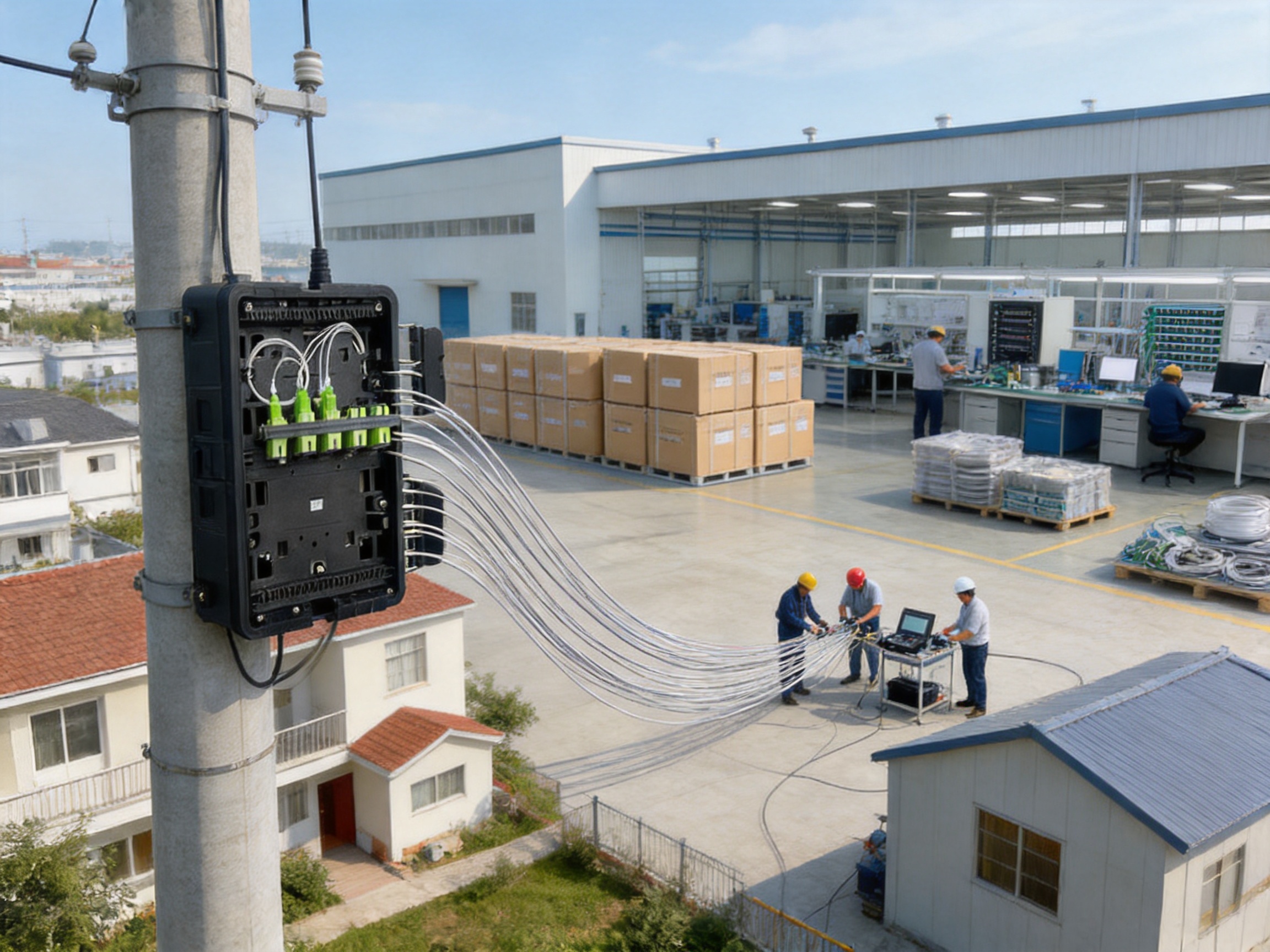
Modern fiber access networks require more than high-capacity cable. They also require carefully organized distribution points that protect fibers, simplify splicing, accommodate splitters, and provide reliable connections to subscribers. In outdoor deployments, the distribution enclosure must withstand changing weather conditions while remaining easy for technicians to open, configure, and maintain. It must also support different network architectures without consuming unnecessary space or creating complicated installation procedures.
The WM-1001-F023 Fiber Optic Distribution Box is designed to meet these requirements in aerial fiber access networks. It combines fiber distribution, splice management, splitter installation, adapter mounting, and drop-cable termination in a compact outdoor enclosure. With 16 subscriber outlet ports, support for up to 24 fibers, IP65 protection, and compatibility with common PLC splitter and adapter configurations, it provides a practical access point for FTTH, residential, industrial, and other outdoor communication projects.
This article examines the product’s structure, capacity, installation concept, environmental performance, manufacturing strengths, and competitive advantages. It also explains how the enclosure can help network operators reduce deployment complexity, improve fiber organization, and prepare access networks for future service expansion.
1. The Role of Fiber Distribution Boxes in Access Networks
Fiber distribution boxes are essential components between feeder cables and subscriber drop cables. In a typical fiber-to-the-home or fiber-to-the-building network, optical fibers arrive from a central office, remote node, or upstream distribution point. These fibers must then be spliced, split, routed, and connected to outgoing drop cables that serve homes, offices, industrial buildings, or other end users.
A distribution box provides the physical location for these operations. It protects the optical connections from dust, moisture, accidental contact, and mechanical stress. It also gives technicians a defined working area in which to arrange splice trays, adapters, splitters, and cable slack. Without an appropriately designed enclosure, fiber access points can become difficult to maintain, vulnerable to environmental exposure, and prone to routing errors.
Outdoor distribution points present additional challenges. They may be installed on poles, aerial support structures, building exteriors, or other exposed locations. The enclosure must tolerate temperature changes, rain, wind, ultraviolet exposure, and repeated maintenance activity. At the same time, the internal layout must remain compact enough for aerial installation and spacious enough for safe fiber handling.
The WM-1001-F023 addresses these requirements through an integrated design. It is not limited to simple termination. The enclosure supports splicing, splitter installation, adapter placement, cable entry, subscriber output, and fiber routing in one housing. This integrated approach can reduce the number of separate passive components required at an access point and can simplify the overall field installation.
2. Product Overview
The WM-1001-F023 is an aerial fiber optic distribution box intended for fiber access networks. It has a black PP+GF enclosure, a hinged and lockable top cover, a sealing ring, two sealed inlet ports, and 16 outlet ports for subscriber drop cables. Its rated protection level is IP65, making it suitable for outdoor use when installed according to the project’s environmental and mounting requirements.
The enclosure supports a maximum of 24 fibers. One heat-shrink splice tray is provided for a 1 × 24 fiber splicing arrangement. The box can also accommodate either two 1 × 8 PLC metal tube splitters or one 1 × 16 PLC metal tube splitter. The adapter holder provides 16 positions for SC simplex or LC duplex adapters.
These specifications allow the product to serve both direct distribution and splitter-based architectures. A network operator may use the box for organized fiber termination, or install a PLC splitter to distribute an upstream optical signal to multiple subscribers. The selected configuration can therefore be matched to the access design, subscriber density, and service expansion plan.
The overall dimensions are 290 mm × 190 mm × 110 mm. This compact size supports aerial deployment while providing internal working space for cable routing and fiber management. The clamshell layout is intended to keep cable paths neat and accessible, helping technicians identify connections and perform maintenance more efficiently.
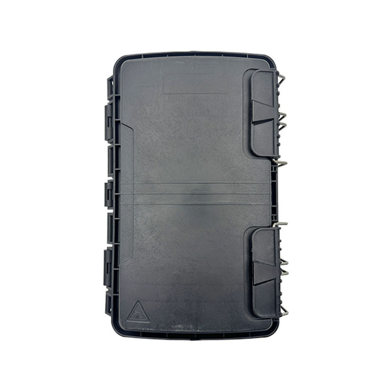
WM-1001-F023 Fiber Optic Distribution Box
3. Enclosure Material and Outdoor Protection
3.1 PP+GF Construction
The enclosure is manufactured from PP+GF material, referring to polypropylene reinforced with glass fiber. This type of engineering plastic is commonly used where a balance of weight, structural strength, dimensional stability, and environmental resistance is required. Compared with a conventional metal box, a reinforced plastic enclosure can reduce weight and simplify handling during aerial installation.
Glass-fiber reinforcement can also improve the rigidity of polypropylene. This is valuable for a hinged enclosure that must remain stable during opening, closing, locking, and cable installation. A stable housing helps protect the internal splice tray and adapter holder from unnecessary movement or deformation.
The material selection also supports corrosion-resistant outdoor deployment. In locations where salt air, humidity, or industrial pollutants may affect exposed metal surfaces, a reinforced polymer enclosure can offer a practical alternative. The black RAL 9005 finish provides a consistent appearance and is appropriate for many outdoor telecommunications installations.
3.2 IP65 Protection
The IP65 rating indicates that the enclosure is designed to prevent dust ingress and to withstand water jets from different directions under defined test conditions. This protection level is suitable for many outdoor fiber access applications, including aerial distribution points, residential access nodes, and industrial-area communication installations.
The sealing ring contributes to the water-resistant structure. The two inlet ports are sealed with rubber seals, helping prevent moisture and contaminants from entering around incoming cables. Proper cable preparation, correct sealing, and appropriate tightening remain important because enclosure protection depends on installation quality as well as product design.
For network operators, IP65 protection can reduce the risk of environmental damage to passive optical connections. A protected internal environment helps preserve splice quality, connector cleanliness, and fiber routing stability. It can also reduce the frequency of corrective maintenance caused by dust or water exposure.
3.3 Compact Aerial Form Factor
Aerial equipment must balance capacity with weight and physical size. An enclosure that is too large can complicate pole or strand mounting, while an enclosure that is too small may force tight bends and difficult maintenance work. The dimensions of the WM-1001-F023 provide a compact platform for 24 fibers, a splice tray, splitter options, and 16 subscriber ports.
The compact enclosure is especially useful where access points must be installed on poles or other elevated structures. A smaller housing can make transportation, positioning, and field handling more manageable. It can also reduce visual and physical obstruction in dense aerial network environments.
4. Internal Structural Design
4.1 Hinged and Lockable Top Cover
The hinged top cover allows the enclosure to be opened without fully removing the cover from the work area. This is useful during installation and maintenance because the technician can access the internal components while the cover remains connected to the housing. The lockable design provides an additional level of physical control after the enclosure has been commissioned.
A lockable cover helps discourage unauthorized access and reduces the likelihood of accidental opening caused by vibration or outdoor movement. It also gives network operators a simple method for controlling access to the internal splice and distribution area.
For technicians, the hinged design can improve working efficiency. Instead of handling a loose cover at an elevated location, the cover stays attached to the enclosure. This can be particularly helpful during aerial installation, where tools and components must be managed carefully.
4.2 Clamshell Cable Management
The clamshell design is intended to support neat cable routing. Fiber cables and drop cables can be directed through defined paths rather than being placed randomly inside the housing. Organized routing reduces the possibility of sharp bends, excessive tension, or accidental interference with the splice tray and adapter holder.
Neat cable routing is not only an aesthetic benefit. It has a direct effect on maintenance quality. When cable paths are visible and logically arranged, technicians can identify fiber destinations more quickly. This can reduce troubleshooting time and lower the risk of disconnecting the wrong subscriber during service work.
The internal layout also supports the separation of major functions. Fiber splicing, splitter placement, adapter termination, and cable entry can be arranged in a controlled manner. Such functional organization is important in access networks where the box may be opened multiple times over its service life.
4.3 Sealing and Entry Arrangement
The box includes two inlet ports for incoming cables. These ports support cable diameters from approximately 7 mm to 18 mm and use rubber seals. The broad diameter range gives installers flexibility when working with different feeder or distribution cable constructions.
Entry ports must be prepared carefully to preserve the enclosure’s environmental protection. The selected seal should match the cable diameter, and unused openings should remain properly closed. When these practices are followed, the sealing system can help maintain a protected internal environment while allowing the enclosure to serve a range of cable configurations.
5. Fiber Capacity and Splicing Performance
The maximum supported fiber count is 24 cores. This capacity is suitable for access nodes serving a moderate number of subscribers or for distribution points that require a balance between current demand and future expansion.
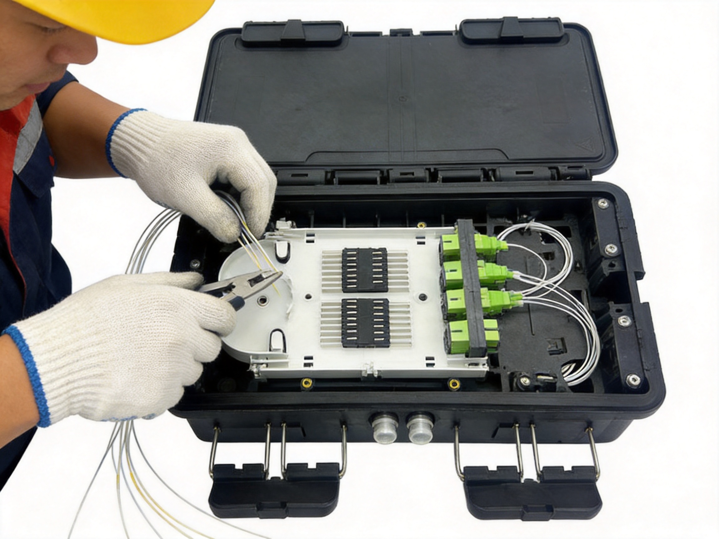
One splice tray is supplied, supporting a 1 × 24 fiber heat-shrink splicing configuration. Heat-shrink splice protection sleeves provide a structured method for protecting fusion splice points. They help shield the splice area from mechanical disturbance and support orderly placement within the tray.
A 24-fiber capacity is well matched to the 16 subscriber outlet arrangement. Depending on the network design, some fibers may be used for active subscribers, reserve capacity, splitter input and output paths, or future expansion. The additional capacity can help operators avoid replacing the enclosure when network demand increases within the supported limit.
The splice tray provides a dedicated location for splicing rather than forcing splices to share space with loose cables or adapter connections. This separation improves fiber identification and makes future maintenance more controlled. It also helps reduce the risk of bending or pulling fibers while technicians work on another part of the box.
The supplied accessories include fusion splice protection sleeves. According to the provided configuration, one set of 16 fusion splice protection sleeves is included. This supports deployment preparation and reduces the need to source every small installation component separately.
6. Splitter and Adapter Compatibility
6.1 PLC Splitter Options
The WM-1001-F023 supports two 1 × 8 PLC metal tube splitters or one 1 × 16 PLC metal tube splitter. This gives the enclosure flexibility for different passive optical network layouts.
A 1 × 8 splitter divides one optical input into eight outputs. Two such splitters can be used where the network requires two groups of eight outputs or where the operator wants to separate service areas within the same enclosure. A 1 × 16 splitter provides a single centralized split ratio suitable for serving up to 16 downstream paths, subject to optical power budgets and the wider network design.
PLC splitter compatibility is a major practical feature because it allows the box to perform both distribution and centralized splitting. Without splitter support, a separate splitter housing or additional access point might be needed. Integrating the splitter into the distribution box can reduce equipment count, simplify the physical network, and make subscriber connections easier to organize.
The use of metal tube splitter formats also supports a compact internal arrangement. Installers can select the splitter configuration based on the optical architecture, subscriber count, and service activation plan. This adaptability is useful for projects that serve different types of neighborhoods or deployment zones.
6.2 Adapter Holder
The adapter holder supports 16 positions for SC simplex or LC duplex adapters. SC simplex adapters are frequently used in access networks because of their practical push-pull connection format. LC duplex adapters provide a higher-density option where two optical channels or compact connector arrangements are required.
Supporting both SC simplex and LC duplex formats gives operators more flexibility when standardizing network hardware. It also helps the same enclosure accommodate different customer premises equipment, distribution cable assemblies, or project specifications.
A dedicated adapter holder keeps connectors aligned and reduces the chance of loose adapters moving inside the box. Organized adapter placement supports faster identification during testing and service activation. It also makes it easier to preserve connector bend-radius requirements and avoid unnecessary strain on patch fibers.
7. Subscriber Port Configuration
The enclosure provides 16 outlet ports for 2 × 3 mm drop cables. This configuration is designed for subscriber connections in FTTH and similar access networks. Sixteen ports make the product suitable for a neighborhood access point, a small residential cluster, an industrial compound, or an aerial distribution location serving a defined group of users.
The 2 × 3 mm drop cable format is compact and commonly suited to last-mile routing. By providing dedicated outlet ports, the enclosure creates a cleaner transition between the protected internal distribution area and the external subscriber cables.
The 16-port configuration can also help network operators plan installation capacity. An access node can be assigned to a defined service area, with each outlet corresponding to an individual subscriber route or downstream connection. This makes documentation, testing, and troubleshooting easier than an unstructured cable exit arrangement.
When combined with a 1 × 16 PLC splitter, the 16 outlet ports provide a straightforward relationship between splitter outputs and subscriber drops. When configured with two 1 × 8 splitters, the same port count can be divided into two logical groups. This flexibility supports different network planning approaches without changing the main enclosure.
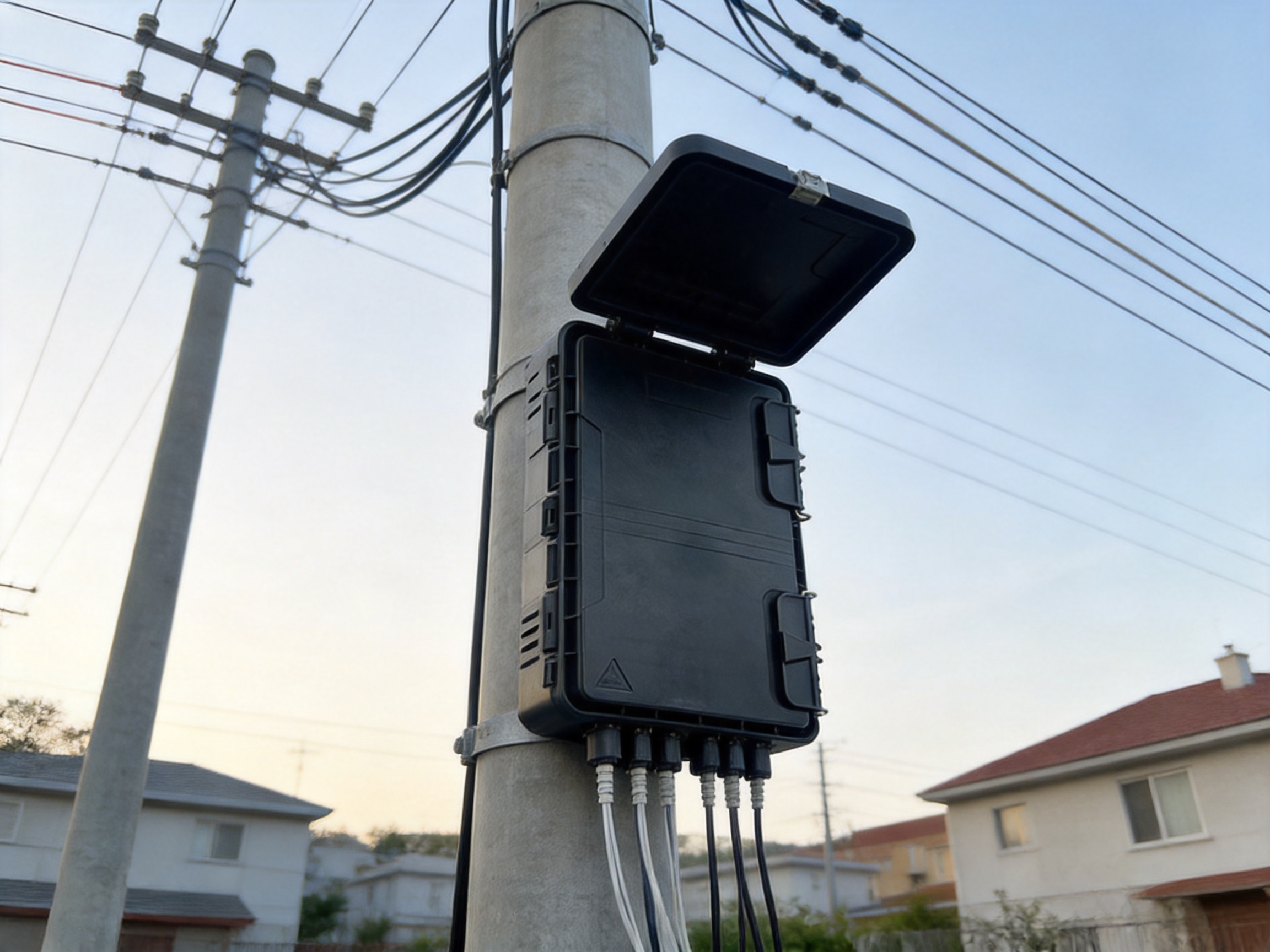
8. Installation and Deployment Applications
8.1 FTTH Fiber Access Networks
Fiber-to-the-home networks require numerous distribution points close to subscribers. The WM-1001-F023 can be used as an aerial access node where feeder fibers are divided and routed toward homes. Its 16 subscriber ports provide a suitable capacity for small service areas and staged neighborhood deployment.
The box can support initial installation with a limited number of active subscribers while retaining space for future connections. Operators may install the enclosure before the entire service area is connected, then activate additional ports as customers subscribe. This approach can help distribute capital expenditure over the network’s growth period.
8.2 Aerial Distribution Points
The product is specifically intended for aerial mounting. Aerial deployment can be valuable in locations where underground construction is expensive, disruptive, or technically difficult. Rural roads, established residential districts, industrial sites, and areas with challenging ground conditions may benefit from overhead fiber infrastructure.
The compact size, reinforced plastic enclosure, hinged cover, and aerial accessories support installation on elevated structures. The enclosure can act as a controlled transition point between an incoming distribution cable and multiple outgoing drop cables.
8.3 Residential Areas
In residential access networks, the distribution box may be positioned near a group of homes, apartment buildings, or housing blocks. The 16-port structure allows the operator to create a localized distribution zone. The lockable cover and organized internal layout support routine service activation and maintenance.
Residential networks often experience gradual growth. An enclosure with splitter support and spare fiber capacity can help operators adapt to subscriber additions without redesigning the entire access segment. The capacity should, of course, be evaluated against expected demand and the optical budget for the specific project.
8.4 Industrial and Commercial Areas
Industrial parks, commercial compounds, and distributed facilities may require fiber connections to offices, security systems, production buildings, and communication cabinets. The WM-1001-F023 can provide a compact outdoor distribution point for these applications.
Its ability to combine splicing and distribution is useful where space is limited or where multiple smaller buildings need to be served from one aerial or exterior node. The IP65 enclosure can help protect passive optical connections in outdoor industrial environments, provided that the overall installation is appropriate for the site conditions.
9. Advantages Compared with Conventional or Less Integrated Boxes
9.1 More Functions in One Enclosure
Some basic outdoor boxes provide only cable termination. Others may offer splicing but lack a dedicated splitter compartment or sufficient adapter positions. The WM-1001-F023 combines these functions in one platform. It supports fiber splicing, PLC splitter installation, adapter mounting, cable entry, and subscriber distribution.
This integration can reduce the number of enclosures needed at a network node. Fewer enclosures may mean fewer mounting operations, fewer cable transitions, and a simpler maintenance map. It can also create a more orderly installation with fewer exposed interconnection points.
9.2 Flexible Splitter Configuration
The ability to install two 1 × 8 splitters or one 1 × 16 splitter gives the product an advantage over boxes designed for only one splitter format. Operators can select a configuration that matches the optical architecture and service area.
This flexibility is particularly valuable for contractors and network owners managing multiple project types. One enclosure platform can be used across several deployment models, reducing the need to maintain a large variety of specialized boxes.
9.3 Balanced Capacity
The combination of 24-core maximum fiber support and 16 subscriber outlets provides a useful balance. The enclosure is compact enough for aerial installation but not limited to a very small number of connections. The spare fiber capacity can support reserve paths, network growth, and different splitting arrangements.
Compared with a smaller box, this design offers greater expansion potential. Compared with a much larger cabinet, it can reduce installation space, handling effort, and visual impact. This balanced capacity is one of the product’s main practical advantages.
9.4 Improved Maintenance Access
The hinged top cover, dedicated splice tray, adapter holder, and clamshell layout are intended to make maintenance more manageable. Technicians can access the internal components without dismantling the entire housing. Clearer organization also reduces the chance of disturbing unrelated fibers while working on a particular subscriber connection.
Maintenance efficiency has a direct effect on operational cost. A box that allows faster fault isolation and service activation can help reduce labor time. It may also lower the risk of accidental fiber damage during routine work.
9.5 Outdoor Suitability
IP65 protection, a sealing ring, rubber-sealed cable entries, and reinforced polymer construction make the enclosure suitable for many outdoor access situations. These features give it an advantage over indoor-only distribution products or enclosures that do not provide a comparable environmental sealing structure.
10. Manufacturing Strengths and Quality-Oriented Production
The product is manufactured by Wanma Technology Co., Ltd., a company established in 1997 and focused on communication cabinets, communication electronic equipment, and passive optical components. Its product applications include Ethernet networks, optical communication networks, central equipment rooms, high-speed railway systems, and urban rail transit systems.
This broad industry experience is relevant to the development of fiber distribution hardware. Outdoor optical enclosures must combine mechanical design, passive optical organization, material selection, sealing, and installation practicality. A manufacturer with experience across communication infrastructure can apply lessons from multiple deployment environments to product development.
10.1 Product Development Based on Application Requirements
The WM-1001-F023 reflects a product development approach centered on field requirements. Its design addresses specific needs: aerial mounting, 16 subscriber ports, 24-fiber capacity, splitter compatibility, splice management, and outdoor sealing. These are not isolated specifications; they work together to support a complete access-network use case.
The use of a hinged lockable cover, defined cable entry ports, dedicated adapter positions, and a clamshell structure suggests attention to installation and maintenance workflows. A successful enclosure is not judged only by its dimensions or material. It must also be usable by technicians in real deployment conditions.
10.2 Integrated Manufacturing and Product Consistency
Wanma Technology develops, manufactures, and markets its own branded products while also providing integrated solutions for customized products. This capability can support closer coordination between product design, production, inspection, packaging, and customer requirements.
For communication infrastructure, manufacturing consistency is important because small differences in enclosure dimensions, sealing interfaces, adapter holder positions, or mounting components can affect field installation. A controlled product platform helps operators standardize deployment methods and replacement procedures.
10.3 Material and Structural Control
The use of PP+GF requires controlled material preparation and molding conditions to achieve consistent structural performance. Enclosure manufacturing must account for wall thickness, hinge alignment, cover fit, cable-entry geometry, locking points, and sealing interfaces. These factors influence the enclosure’s practical performance after installation.
Quality-oriented production should include dimensional checks, visual inspection, closure and fit verification, and review of accessory completeness. For an outdoor fiber box, the final product must not only look uniform; the cover, sealing ring, ports, and internal mounting features must work together as a complete system.
10.4 Packaging and Logistics Capability
The provided export packaging specification includes individual polyethylene bags and inner boxes, with 10 units packed in an outer carton. The outer carton uses five-layer corrugated paper construction, with a specified thickness range of approximately 5–8 mm. The listed carton size is 410 mm × 330 mm × 610 mm, with a packed weight of approximately 18–19 kg.
Protective packaging is important for optical equipment because transportation damage can affect hinges, locks, seals, adapter holders, and mounting points before the product reaches the installation site. Structured export packaging helps support product condition during international logistics and warehouse handling.
10.5 Compliance Awareness
The product information identifies compliance with RoHS 2011/65/EU and amendment directive (EU) 2015/863, as well as REACH Regulation 1907/2006/EC. These environmental and chemical compliance declarations are important for customers purchasing communication equipment for international projects.
Compliance documentation can simplify procurement review and support responsible material selection. It also demonstrates that the product is positioned for use in markets where restrictions on hazardous substances and chemical reporting are part of the purchasing process.
11. Technical Specification Summary
Item |
Specification |
Product type |
Fiber optic distribution box |
Model |
WM-1001-F023 |
Primary application |
Aerial fiber access networks |
Enclosure material |
PP+GF |
Color |
Black, RAL 9005 |
Dimensions |
290 mm × 190 mm × 110 mm |
Maximum fiber capacity |
24 cores |
Splice tray |
One tray, 1 × 24 fiber heat-shrink type |
Splitter support |
Two 1 × 8 PLC metal tube splitters or one 1 × 16 PLC metal tube splitter |
Adapter holder |
16 positions for SC simplex or LC duplex adapters |
Inlet ports |
Two ports with rubber seals |
Supported cable entry diameter |
Approximately Φ7–Φ18 |
Outlet ports |
16 ports for 2 × 3 mm drop cables |
Protection rating |
IP65 |
Operating temperature |
−40 °C to +85 °C |
Storage temperature |
−40 °C to +85 °C |
Environmental compliance |
RoHS and REACH compliant according to the provided product information |
12. Installation Planning Considerations
Before installation, the network designer should confirm the required fiber count, splitter ratio, connector type, drop-cable construction, and available mounting structure. The WM-1001-F023 supports a defined configuration, so the project should verify that the selected cables and accessories fall within the specified ranges.
The incoming cable diameter should be checked against the 7 mm to 18 mm entry-port range. The drop cables should match the 2 × 3 mm outlet-port configuration. If unusual cable types are planned, the installer should verify compatibility before field deployment.
Fiber routing should preserve appropriate bend radii and avoid excessive tension. The splice tray should be installed so that heat-shrink sleeves remain securely positioned. Fibers should be labeled consistently, particularly where the box contains a splitter and multiple subscriber outputs.
The box should be mounted in a location that allows technicians to open the hinged cover safely. Even when the product is installed aerially, there should be enough working clearance for splicing, connector cleaning, testing, and future expansion. The locking mechanism should be checked after commissioning, and all cable seals should be inspected before the enclosure is closed.
Unused ports and openings should be sealed according to the installation procedure. Environmental protection can be compromised if a cable entry is left open or if a rubber seal is incorrectly fitted. Good installation practice is therefore essential to achieving the intended IP65 performance.
13. Operational and Maintenance Benefits
A well-organized distribution box can improve the daily operation of an access network. When subscriber ports, splitter outputs, and splice points are clearly arranged, technicians can perform service activation with less disruption. A logical layout also helps field teams trace a fiber from the incoming cable to the correct subscriber outlet.
The lockable cover supports basic physical access control. The sealing system helps protect passive optical components from outdoor contamination. The dedicated tray reduces the likelihood that splices will be crushed or tangled with other cables. The adapter holder keeps connectors in known positions for inspection and testing.
Maintenance benefits become increasingly important as the subscriber base grows. A distribution box may initially contain only a small number of active connections, but it can later become a busy node. The 16-port capacity and 24-fiber support provide a practical foundation for controlled expansion within the limits of the enclosure.
Operators can also benefit from standardized deployment. If the same model is used across multiple access areas, technicians become familiar with the internal layout, port arrangement, and maintenance procedure. Standardization can reduce training time and improve consistency in network documentation.
14. Why the Product Is Suitable for Network Modernization
Fiber network modernization is not limited to replacing copper with optical cable. It also requires upgrading the passive infrastructure that organizes and protects the new fiber routes. Distribution boxes are important modernization components because they determine how easily new subscribers, splitters, and service branches can be added.
The WM-1001-F023 supports modernization through its combination of capacity and flexibility. It can accept a 1 × 16 splitter for centralized subscriber distribution, or two 1 × 8 splitters for segmented deployment. It can support SC simplex or LC duplex adapters, allowing the network operator to work with different connection standards.
The outdoor housing is suitable for extending fiber services into areas where existing infrastructure may be mounted on poles or exterior structures. Its compact form can help operators add optical distribution points without installing large cabinets. This may be useful in rural broadband projects, older neighborhoods, industrial estates, and mixed-use developments.
Because the enclosure includes splicing and distribution functions, it can support phased construction. An operator may route feeder cable to the box first, complete the required splices, install the selected splitter, and activate subscriber outlets as demand develops. This approach can help align network investment with actual service growth.
15. Company Capability and Industry Experience
Wanma Technology Co., Ltd. has operated since 1997 and focuses on communication cabinets, communication electronic equipment, and passive optical components. Its products are used in Ethernet networks, optical communication networks, central equipment rooms, national high-speed railways, and urban rail transit systems.
Experience in these sectors indicates familiarity with infrastructure products that must perform reliably in organized, demanding, and long-life network environments. Railway and transit applications often require careful equipment planning, clear installation procedures, and stable supply capability. These requirements can contribute to a disciplined approach to communication product development.
The company develops and manufactures its own branded products and also offers integrated solutions for customized products. This combination may benefit customers with standard requirements as well as those needing adjustments for a particular project. Customization can involve configuration, packaging, mounting arrangements, labeling, or other project-specific details, subject to technical review.
With a sales network covering more than 20 countries and regions, including the United States, Australia, the United Kingdom, Italy, South Africa, and Ghana, the company has experience serving international customers. A global customer base requires attention to export packaging, documentation, communication, delivery planning, and regional project expectations.
The company emphasizes reliable product quality, timely delivery, and long-term strategic partnerships. These strengths are relevant to fiber access deployments, where a project may require repeated orders, consistent product configurations, and replacement units over an extended construction or maintenance period.
16. Procurement Guidance for Project Owners
Project owners evaluating the WM-1001-F023 should begin by matching the product’s capacity to the planned subscriber area. The enclosure supports 16 outlet ports and up to 24 fibers. This is appropriate for many small and medium access nodes, but larger subscriber clusters may require multiple boxes or a higher-capacity cabinet.
The selected splitter configuration should be determined from the optical design. A 1 × 16 PLC splitter may be suitable for a single centralized distribution group, while two 1 × 8 splitters may be preferable for two separate service branches. Optical loss, feeder distance, drop-cable length, and receiver sensitivity should be calculated independently by the network designer.
Connector selection should also be confirmed. The adapter holder supports SC simplex or LC duplex formats, but the installed pigtails, patch cords, splitters, and customer equipment must use compatible connectors. Standardizing the connector type across a project can simplify stock management and maintenance.
Procurement teams should review the included accessory kit. The provided materials include cable ties, adhesive tape, an expansion screw set, fusion splice protection sleeves, and a coiled tube. These accessories can assist with deployment, although the installer may still need project-specific tools, labels, mounting hardware, cleaning supplies, and testing equipment.
For international projects, buyers should also confirm carton quantity, outer-box dimensions, packed weight, labeling requirements, and delivery terms. The supplied export carton information can help logistics teams estimate warehouse space and transportation requirements.
17. Frequently Asked Questions
17.1 What is the main purpose of the WM-1001-F023?
The WM-1001-F023 is a fiber optic distribution box for fiber distribution, splicing, splitter installation, adapter management, and subscriber drop-cable connection in outdoor access networks.
17.2 Is the box suitable for aerial installation?
Yes. Aerial mounting is the specified mounting application. The product information also identifies aerial accessories and an aerial mount for deployment on elevated network structures.
17.3 How many subscriber connections can it support?
The box provides 16 outlet ports for 2 × 3 mm drop cables. The actual number of active subscribers will depend on the selected splitter configuration, network design, and service requirements.
17.4 What is the maximum fiber capacity?
The maximum supported fiber count is 24 cores. One 1 × 24 fiber heat-shrink splice tray is provided.
17.5 Which PLC splitters can be installed?
The enclosure supports either two 1 × 8 PLC metal tube splitters or one 1 × 16 PLC metal tube splitter.
17.6 Which adapters are supported?
The adapter holder supports 16 positions for SC simplex or LC duplex adapters.
17.7 What cable diameters are supported at the inlet ports?
The cable entry ports support diameters from approximately Φ7 to Φ18. The installer should confirm the actual cable and seal combination before deployment.
17.8 What environmental protection does the enclosure provide?
The enclosure has an IP65 protection rating. It includes a sealing ring and rubber-sealed inlet ports to help protect internal components from dust and water exposure under the specified conditions.
17.9 What temperature range is supported?
The stated operating temperature range is −40 °C to +85 °C. The stated storage temperature range is also −40 °C to +85 °C.
17.10 What is the enclosure material?
The enclosure is made from PP+GF, or glass-fiber-reinforced polypropylene. It is black with the color reference RAL 9005.
17.11 Does the product support future network expansion?
It can support staged expansion within its 24-fiber and 16-outlet limits. Spare fiber capacity and unused subscriber ports may be reserved for future service activation, subject to the project’s optical and physical planning.
17.12 What accessories are included?
The listed accessory kit includes 10 cable ties, one piece of adhesive tape, six expansion screw sets, one set of 16 fusion splice protection sleeves, and one 8 mm diameter coiled tube with a length of 500 mm.
17.13 Which standards and compliance requirements are identified?
The provided product information identifies compliance with RoHS 2011/65/EU and amendment directive (EU) 2015/863, as well as REACH 1907/2006/EC.
17.14 Who can benefit from this product?
Telecommunications operators, FTTH contractors, broadband infrastructure developers, industrial network integrators, and distributors of passive optical equipment can use the product for outdoor fiber access deployments.
18. Conclusion
The WM-1001-F023 Fiber Optic Distribution Box is a compact and flexible platform for outdoor fiber access networks. Its main strengths are the combination of 24-fiber capacity, 16 subscriber outlets, PLC splitter support, SC simplex and LC duplex adapter compatibility, dedicated splice management, and IP65 environmental protection.
The hinged lockable cover and clamshell layout support easier field work, while the sealing ring and rubber-sealed cable entries help protect the internal optical connections. The PP+GF enclosure provides a practical balance between structural strength, manageable weight, and outdoor suitability. Its aerial mounting application makes it relevant to FTTH expansion, residential distribution, industrial access points, and other above-ground fiber deployments.
Compared with less integrated distribution boxes, the product can reduce the need for separate splitter and splice enclosures. Its flexible configuration allows operators to select between two 1 × 8 PLC splitters and one 1 × 16 PLC splitter. The capacity is large enough for many localized access nodes while remaining compact enough for aerial installation.
Manufactured by a company with long-term experience in communication infrastructure, passive optical components, railway communication applications, and international supply, the product is positioned as a practical component for standardized and scalable network construction. When correctly specified and installed, it can help network operators create cleaner fiber routes, simplify maintenance, and prepare outdoor access networks for continued subscriber growth.
References
1. Product specification and technical information for the WM-1001-F023 Fiber Optic Distribution Box, supplied for this article.
2. International Electrotechnical Commission, Degrees of Protection Provided by Enclosures, IP Code classification reference.
3. European Union, Restriction of Hazardous Substances Directive 2011/65/EU and amendment directive (EU) 2015/863.
4. European Union, Registration, Evaluation, Authorisation and Restriction of Chemicals Regulation 1907/2006/EC.
5. General engineering guidance for fiber optic splicing, connector management, passive optical network distribution, and outdoor enclosure installation.
6. Manufacturer information concerning communication cabinets, passive optical components, communication electronic equipment, and integrated network infrastructure solutions.
Product: WM-1001-F023 Fiber Optic Distribution Box
PREV:Fiber Optic Splice Closure for Reliable FTTH, FTTB, and Railway Communication Networks
NEXT:Quick Connector Solutions for Reliable Fiber Installation and Network Modernization
NEXT:Quick Connector Solutions for Reliable Fiber Installation and Network Modernization
Interested in cooperation or have questions?
Related products
-
-
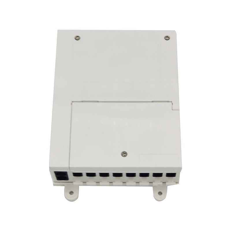
Application:This product integrates the function of splicing with splitting, suitable for the straight through or branch connection, and terminal connection in optical system, as well as protection co...
See Details -
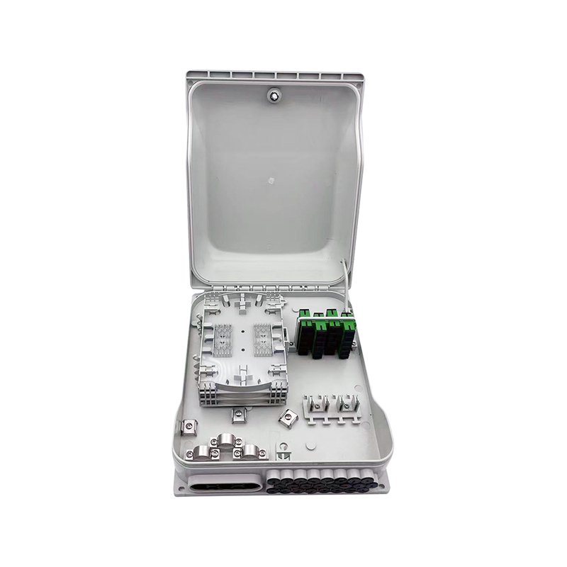
DescriptionThe speed outdoor 24-port enclosure is designed to bring a high-speed fibre connection and greater bandwidth closer to home and business. FTTH offers the user flexibility and the opportunit...
See Details -
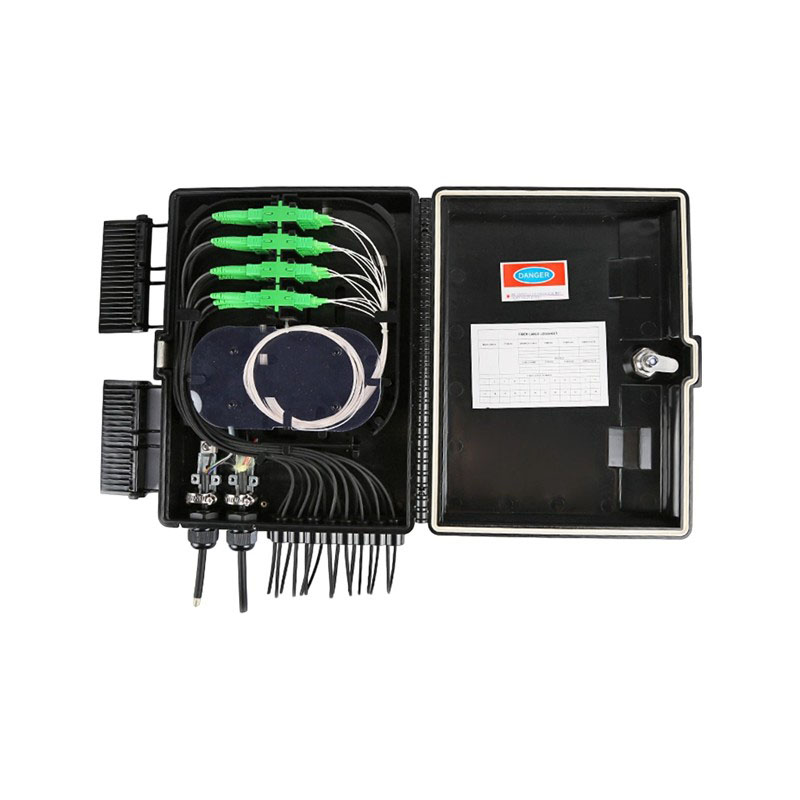
Description: The equipment is used as a termination point for the feeder cable to connect with drop cable in FTTx communication network system. The fiber splicing, splitting, distribution can be done ...
See Details
Ready to Get started ? Contact Us Now !

Product.
Contact Details.
-
 +86 13958188250
-
 +86 13958188250
-
 [email protected]
-
 AUDIT Email:[email protected]
- Wanma Industrial Park Taihu Yuan Town Lin'an District Hangzhou City China.
QR Code

Copyright © Wanma Technology Co., Ltd. All Rights Reserved.
Privacy
Custom Ethernet Optical Network Railway Transit Equipments Suppliers
