

 English
 Français
 Español
 Português
 عربى





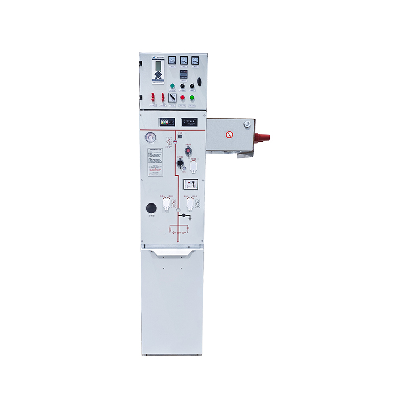


Product OverviewThe indoor AC metal-clad withdrawable switchgear is a core component in medium-voltage power distribution systems. It boasts numerous features such as safety, reliability, and conveni...
See DetailsIndoor AC Metal-Clad Withdrawable Switchgear: Safe, Flexible, and Intelligent Medium-Voltage Power Distribution
Content
- 1 1. The Role of Withdrawable Switchgear in Medium-Voltage Systems
- 2 2. Product Overview and Application Scope
- 3 3. Metal-Clad Construction and Advanced Cabinet Manufacturing
- 4 4. Four Independent Functional Compartments
- 5 5. Safety Through a Complete Five-Prevention Interlocking System
- 6 6. Shutters, Enclosure Protection, and Internal Fault Control
- 7 7. Modular Withdrawable Trolley Design
- 8 8. Electrical Performance and Rated Parameters
- 9 9. Advantages Compared with Conventional Alternatives
- 10 10. Intelligent Upgrade Capability
- 11 11. Manufacturing Strengths and Quality-Oriented Production
- 12 12. Installation, Commissioning, and Maintenance Considerations
- 13 13. Standards and Compliance Framework
- 14 14. Selecting the Correct Configuration
- 15 15. Typical Benefits for Facility Owners and Operators
- 16 16. Q&A
- 16.1 Q1: What is the main purpose of this indoor AC metal-clad withdrawable switchgear?
- 16.2 Q2: What is the rated voltage of the equipment?
- 16.3 Q3: What rated current options are available?
- 16.4 Q4: What does “withdrawable” mean?
- 16.5 Q5: How does the equipment help prevent operating errors?
- 16.6 Q6: How are live primary contacts protected when the trolley is withdrawn?
- 16.7 Q7: Can the switchgear accommodate multiple cables per phase?
- 16.8 Q8: Can the switchgear be connected to a distribution automation system?
- 16.9 Q9: Is the switchgear suitable for humid indoor environments?
- 16.10 Q10: What standards are referenced for the product?
- 16.11 Q11: What makes the cabinet construction different from a basic enclosure?
- 16.12 Q12: What should be confirmed before ordering?
- 17 17. Conclusion
- 18 References
- 19 Product: Indoor Ac Metal-Clad Withdrawable Switchgear
Modern electrical systems require switchgear that can do more than simply connect and disconnect circuits. Medium-voltage distribution equipment must withstand electrical stress, protect personnel, limit the effects of internal faults, support reliable maintenance, and adapt to increasingly intelligent power-management systems. The indoor AC metal-clad withdrawable switchgear discussed in this article is designed to address these requirements in a single, coordinated solution.
This type of switchgear is a core component of medium-voltage power distribution systems. It is used for the safe reception, controlled distribution, flexible switching, measurement, and protection of electrical energy. Its withdrawable trolley structure, metal-clad construction, compartmentalized design, mechanical interlocking, pressure-relief channels, and intelligent upgrade interfaces make it suitable for demanding applications in power plants, substations, industrial facilities, civil buildings, municipal infrastructure, hotels, offshore oil platforms, and nuclear power plants.
With a rated voltage of 12 kV and rated current options from 630 A to 4000 A, the equipment covers a broad range of medium-voltage distribution requirements. It also provides short-circuit breaking current options of 25 kA, 31.5 kA, and 40 kA, along with internal arc classifications corresponding to these fault levels. These characteristics allow system designers to select a configuration according to the electrical capacity, fault level, operating environment, and maintenance strategy of a particular installation.
1. The Role of Withdrawable Switchgear in Medium-Voltage Systems
Medium-voltage switchgear forms the operational boundary between incoming power sources, transformers, distribution feeders, motors, and downstream electrical loads. It must perform several functions simultaneously. During normal operation, it distributes power and allows authorized personnel to control individual circuits. During abnormal conditions, it must interrupt fault current and prevent damage from spreading to other equipment. During maintenance, it must provide safe isolation and sufficient access for inspection or replacement.
A withdrawable switchgear system performs these functions through a movable circuit breaker trolley. Instead of permanently fixing the circuit breaker inside the cabinet, the breaker is mounted on a truck that can occupy defined positions within the enclosure. These positions normally include the working position, testing position, and disconnected position. This arrangement allows operators to separate the main circuit from the busbar and cable connections without removing the entire cabinet from service.
The withdrawable configuration offers important practical benefits. A circuit breaker can be tested in a controlled position before being returned to service. A defective unit can be removed and replaced more efficiently. Breakers of the same specification can be interchanged, reducing the need to keep a large number of different spare units. Maintenance teams can also work on a removed trolley while another compatible trolley is prepared for installation.
Compared with fixed switchgear, a withdrawable design generally provides greater operational flexibility and shorter equipment-replacement time. Compared with less comprehensively enclosed assemblies, metal-clad switchgear offers stronger separation between compartments and improved protection against accidental contact with live parts. These qualities are particularly valuable in facilities where power continuity, personnel safety, and rapid restoration are critical.
2. Product Overview and Application Scope
The indoor AC metal-clad withdrawable switchgear is intended for indoor medium-voltage AC distribution systems. Its principal tasks include receiving incoming electrical power, distributing power to multiple outgoing circuits, controlling circuit breakers and load circuits, measuring electrical parameters, and isolating faulty or maintenance-related sections of the system.
The equipment may be used in the following application environments:
Power plants require switchgear capable of controlling generator auxiliary systems, plant distribution feeders, and important service loads. Substations use this type of equipment for medium-voltage feeder protection and distribution. Manufacturing enterprises depend on it for the reliable supply of production lines, motors, process systems, and auxiliary equipment.
Civil buildings and hotels may use medium-voltage switchgear to manage transformer incoming circuits, emergency power distribution, mechanical systems, and essential building services. Municipal facilities can apply it in water-treatment systems, public infrastructure, transportation installations, and utility distribution rooms. Offshore oil drilling platforms and nuclear power plants require carefully engineered distribution equipment with strong safety provisions, controlled maintenance procedures, and reliable fault containment.
The equipment is designed for indoor use at an altitude of up to 1000 meters under specified environmental conditions. The normal ambient temperature range is from -25°C to +40°C, with a daily temperature difference of up to 25 K. The average daily relative humidity should not exceed 95%, while the average monthly relative humidity should not exceed 90%. The specified ground horizontal acceleration is up to 2 m/s².
Special consultation with the manufacturer is required when the switchgear will operate at higher altitudes, in very low temperatures, or in areas with severe pollution. Such conditions can influence insulation performance, thermal management, enclosure protection, heater selection, creepage requirements, and the overall equipment configuration.
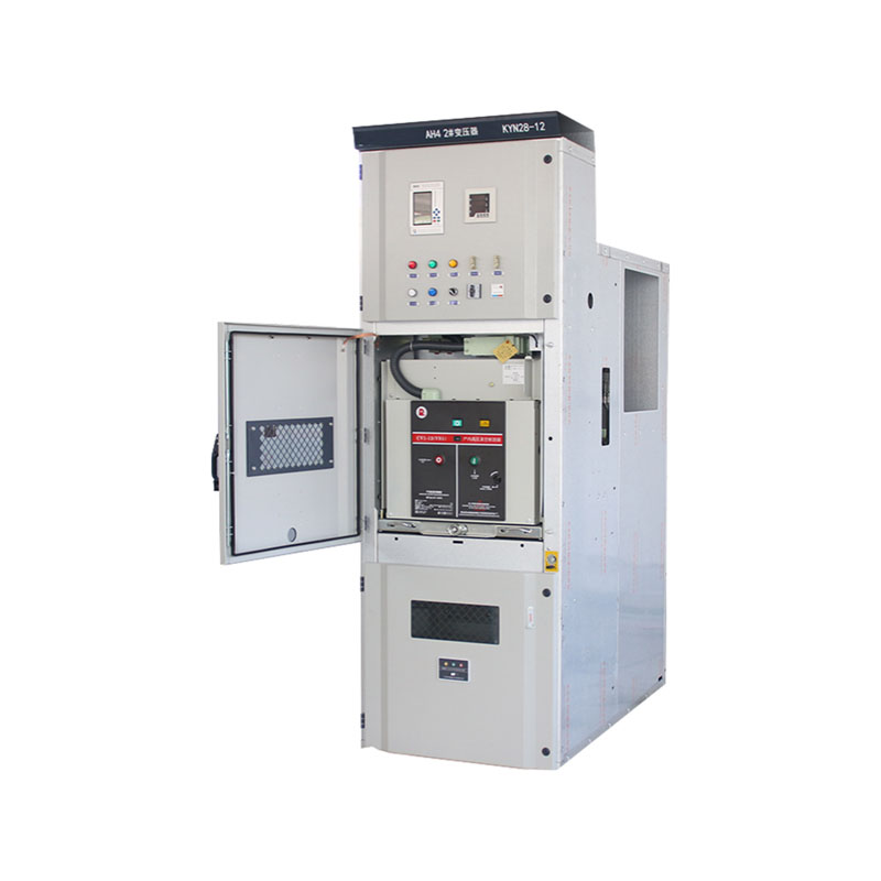
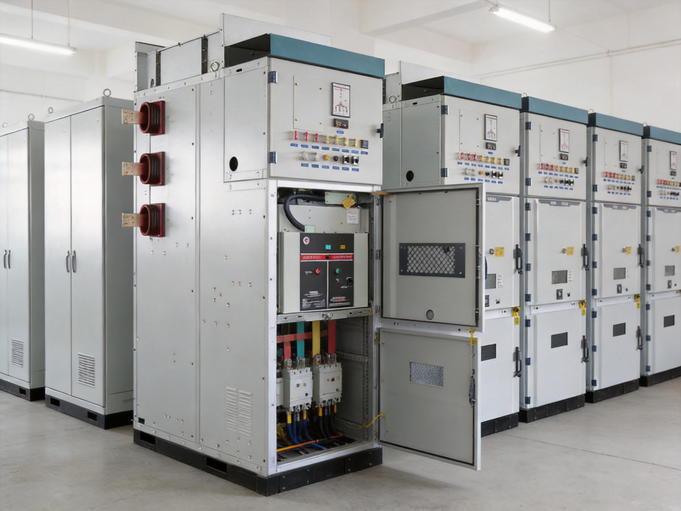
Indoor Ac Metal-Clad Withdrawable Switchgear
3. Metal-Clad Construction and Advanced Cabinet Manufacturing
One of the most important advantages of this switchgear is its engineered metal-clad cabinet structure. The main frame is primarily manufactured from aluminum-zinc-coated thin steel plates. This material choice combines mechanical strength with improved resistance to corrosion. The protective coating is particularly useful for indoor electrical rooms where humidity, condensation, and long-term exposure to industrial atmospheres may affect ordinary steel surfaces.
The plates are processed using CNC machine tools and formed through multiple precision bending operations. CNC processing helps maintain dimensional consistency from panel to panel, while controlled bending produces accurate structural elements with reduced dependence on manual fitting. The resulting components are assembled using rivets or high-strength bolts, creating a robust cabinet frame without unnecessary welding distortion.
The side panels use an inner double-bending process. This method improves rigidity and provides a smooth external surface without visible splicing gaps. The design also avoids exposed screws and unnecessary clearance holes on the sides of the cabinet. These details contribute to a cleaner appearance, reduce potential points of corrosion, and improve the mechanical strength of the enclosure.
A carefully manufactured cabinet has practical advantages beyond appearance. Accurate panel geometry helps maintain reliable alignment between the trolley, primary contacts, shutters, interlocking components, and secondary plug system. Consistent assembly dimensions also support interchangeability between trolleys of the same specification. This is important because the benefits of a withdrawable system depend heavily on the precision of its mechanical interfaces.
The cabinet structure is designed to allow a single unit to be removed and replaced without dismantling adjacent cabinets. This is a valuable feature during fault recovery or planned maintenance. In many distribution applications, reducing the time required to restore an affected feeder is as important as reducing the initial probability of failure. A cabinet that supports quick unit removal can help shorten outage periods and improve the maintainability of the overall installation.
Compared with basic sheet-metal enclosures, this construction approach provides a stronger combination of structural integrity, corrosion resistance, repeatable manufacturing quality, and service accessibility. It also reflects the manufacturing capability of the producer, since the quality of the final switchgear depends on material selection, CNC processing, forming accuracy, fastening methods, inspection procedures, and final assembly control.
4. Four Independent Functional Compartments
The switchgear cabinet is divided into four independent compartments: the circuit breaker trolley compartment, busbar compartment, cable compartment, and relay instrument compartment. This compartmentalized structure is central to the safety and serviceability of the design.
4.1 Circuit Breaker Trolley Compartment
The circuit breaker trolley compartment houses the withdrawable circuit breaker assembly and its operating mechanism. The trolley moves between defined positions and is mechanically guided so that the primary contacts connect or disconnect in a controlled sequence. The compartment is arranged to support operation, testing, removal, and replacement without exposing personnel to unnecessary live components.
4.2 Busbar Compartment
The busbar compartment contains the main busbar system and associated connections. Separating the busbars from the circuit breaker and cable areas reduces the likelihood that work in one area will directly expose personnel or equipment in another. The compartment arrangement also helps contain the consequences of an internal electrical fault and supports directional pressure relief.
4.3 Cable Compartment
The cable compartment provides ample working space for cable termination and inspection. It can accommodate multiple single-core cables connected in parallel on each phase, making the equipment suitable for circuits with higher current requirements or installations that use several parallel cables to achieve the required ampacity.
Generous cable space is an important advantage over compact enclosures that may be difficult to terminate and maintain. Adequate bending radius, clearance, cable support, and access for testing can reduce installation difficulty and help prevent mechanical stress at the terminals. The actual cable arrangement must still be designed according to the applicable electrical standards, cable manufacturer instructions, heat dissipation requirements, and project-specific installation rules.
4.4 Relay Instrument Compartment
The relay instrument compartment contains protection relays, measurement equipment, control components, terminal blocks, intelligent terminals, fault recorders, and other secondary devices. A rotating component beam can be turned through 180 degrees, allowing wiring and maintenance work to be performed without fully dismantling the instrument assembly.
This rotating arrangement improves access during commissioning and troubleshooting. It can reduce wiring time, simplify terminal inspection, and help maintenance personnel reach components located behind the front panel. It also provides greater flexibility when different protection and automation devices are specified for different projects.
Each compartment is provided with an independent pressure-relief channel. If an arc fault occurs, the high-pressure gas generated by the fault can be directed away through the designed relief path. The purpose is to reduce internal pressure accumulation and limit the risk of cabinet rupture. Pressure relief does not eliminate the need for correct installation, arc-fault assessment, safe working procedures, and appropriate room ventilation, but it is an important part of the equipment’s internal fault management strategy.
5. Safety Through a Complete Five-Prevention Interlocking System
Electrical safety depends not only on insulation and enclosure strength but also on preventing incorrect operating sequences. The switchgear includes a comprehensive five-prevention interlocking system intended to reduce the risk of common operating errors.
One important interlock prevents the trolley from being moved while the circuit breaker is closed. This means the trolley cannot be pushed into or pulled out of the connected position while the main circuit is carrying current through a closed breaker. The arrangement helps prevent damage to primary contacts and reduces the risk of an unsafe switching action.
Another interlock allows the grounding switch to be closed only when the trolley is in the test or disconnected position. This prevents the grounding switch from being closed while the main circuit is energized and connected to the busbar. The operating sequence therefore requires the circuit breaker trolley to be separated from the energized primary circuit before grounding operations can take place.
When the grounding switch is open, the rear lower door and rear cabinet door cannot be opened. This prevents personnel from entering the cable or rear connection area while the relevant compartment may still be energized. The interlocking system creates a physical barrier against an unsafe access sequence rather than relying solely on warning labels or operator memory.
Some configurations can also be equipped with electromagnetic locks. These additional devices can enhance interlocking reliability and allow the control system to enforce specific operating conditions. Electromagnetic locking may be useful in substations and distribution rooms with stricter operational control requirements or integration with centralized automation systems.
Interlocking systems should always be tested during commissioning and periodically inspected during the equipment life cycle. Mechanical interlocks, electrical interlocks, control circuits, and position indicators must work together. The presence of an interlock does not replace operator training or documented switching procedures; instead, it adds a physical and logical layer of protection against human error.
6. Shutters, Enclosure Protection, and Internal Fault Control
The switchgear incorporates multiple protective details designed to improve day-to-day safety. The shutters use sliding-groove aluminum-alloy guide rails or specialized shutter mechanisms. They open and close automatically with trolley movement. When the trolley is withdrawn, the shutters close over the static contact boxes.
This automatic shutter action is important because the static primary contacts may remain connected to energized busbars or cable circuits even after the circuit breaker trolley has been removed. Covering these contacts helps prevent accidental contact with live parts during inspection or maintenance. It also creates a more consistent safety condition than a manually operated cover that could be left open unintentionally.
The external cabinet protection level reaches IP4X. This level helps prevent access to hazardous parts by solid objects of the specified size and provides protection against the entry of solid foreign objects under the applicable testing conditions. The protection level between compartments reaches IP2X, helping limit access to dangerous parts and reducing the passage of objects between internal areas.
Protection ratings must be understood in relation to the complete installation. Cable entries, ventilation openings, room conditions, door seals, and site modifications can affect actual protection performance. Unauthorized drilling, poorly fitted cable glands, or missing covers may reduce the effective enclosure protection of the installed equipment.
Heaters can be installed in the circuit breaker compartment and cable compartment to reduce condensation and corrosion in high-humidity environments. Condensation can lower insulation resistance, accelerate corrosion, and create tracking or flashover risks. Heater selection and control should be coordinated with humidity conditions, ventilation, energy consumption, and the operating temperature limits of installed components.
The combination of metal-clad separation, automatic shutters, compartmentalized construction, pressure-relief channels, enclosure protection, and optional anti-condensation heaters gives this switchgear a broader safety design than equipment that relies primarily on a single external enclosure.
7. Modular Withdrawable Trolley Design
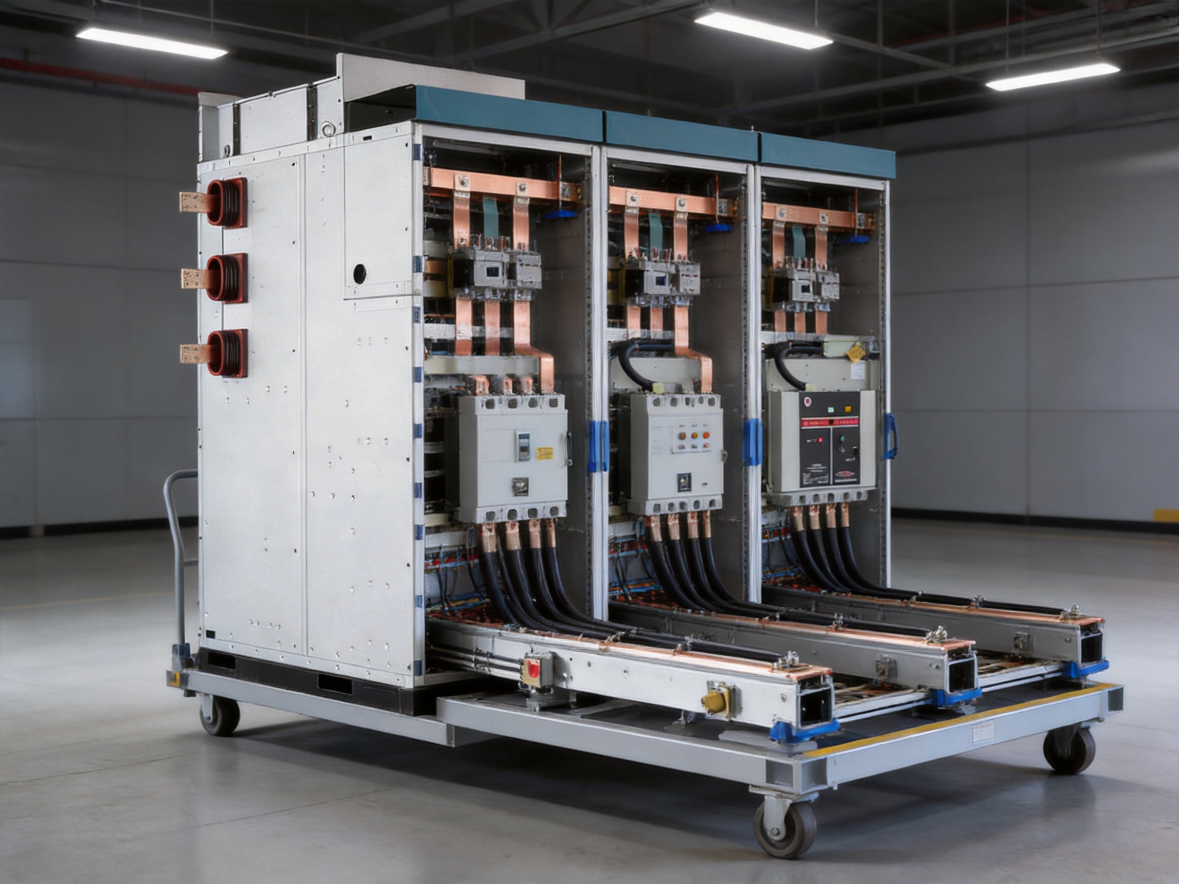
The trolley uses a modular design and can be configured for different purposes. Typical trolley types include circuit breaker trolleys, metering trolleys, and isolation trolleys. Trolleys with the same specification are designed to be freely interchangeable, subject to the applicable configuration and project requirements.
Interchangeability can improve spare-parts management. A facility may be able to maintain a smaller inventory of compatible trolley assemblies instead of stocking a separate, highly specialized unit for every feeder. It can also simplify maintenance planning because a removed trolley can be inspected or repaired away from the energized cabinet.
The trolley is advanced or withdrawn by rotating a nut and screw rod. This mechanism provides controlled movement and helps prevent sudden or uncontrolled travel. A dedicated transfer cart can be used to move the trolley out of the cabinet for maintenance. The transfer cart also supports alignment during insertion and removal, reducing the chance of mechanical impact on the cabinet or primary contacts.
Three trolley positions are provided inside the cabinet:
The working position connects the circuit breaker to the main circuit so that it can perform its intended switching and protection function.
The testing position separates the primary circuit while retaining the required secondary connections for operational checks, control testing, protection-relay verification, and functional commissioning.
The disconnected position provides greater separation from the primary circuit and supports removal, inspection, or maintenance activities according to the approved safety procedure.
Clear positioning improves operational control. It allows operators and maintenance personnel to understand the electrical and mechanical state of the trolley before performing the next action. Position indication should be checked against actual contact status during commissioning and routine inspection.
8. Electrical Performance and Rated Parameters
The switchgear has a rated voltage of 12 kV and a rated frequency of 50 Hz. Rated current options range from 630 A to 4000 A, allowing the equipment to serve both standard medium-voltage feeders and higher-capacity distribution circuits.
The rated power-frequency withstand voltage is 42 kV between phases and between phase and ground. Across the circuit breaker, the corresponding value is 48 kV. The rated lightning impulse withstand voltage is 75 kV between phases and between phase and ground, and 85 kV across the breaker. These values describe the insulation capability under specified test conditions and support coordination with the wider system insulation design.
Short-circuit performance is a major selection factor for medium-voltage switchgear. The specified short-circuit breaking current options are 25 kA, 31.5 kA, and 40 kA. The rated peak withstand current values are 63 kA, 80 kA, and 100 kA, corresponding to the selected short-circuit class. The rated short-time withstand current is listed as 25 kA, 31.5 kA, or 40 kA for the applicable short-duration withstand period, indicated in the supplied specifications as four seconds.
The internal arc classification is listed as 25 kA, 31.5 kA, or 40 kA for one second, depending on the selected design and test configuration. Internal arc classification is relevant to the protection of personnel and equipment in the event of an internal arc fault. Project engineers must verify that the selected arc classification, room arrangement, pressure-relief direction, and installation clearances are suitable for the intended site.
The circuit breaker mechanical life is rated at 20,000 operations. The earthing switch and truck mechanical lives are each rated at 3,000 operations, while the service-position mechanical life is rated at 500 operations. These figures provide a basis for maintenance planning, although actual service life also depends on operating frequency, environmental conditions, fault duty, lubrication, alignment, and maintenance quality.
| Specification | Unit | Value |
|---|---|---|
| Rated voltage | kV | 12 |
| Rated current | A | 630 to 4000 |
| Rated frequency | Hz | 50 |
| Power-frequency withstand voltage, phase-to-phase and phase-to-ground | kV | 42 |
| Power-frequency withstand voltage across breaker | kV | 48 |
| Lightning impulse withstand voltage, phase-to-phase and phase-to-ground | kV | 75 |
| Lightning impulse withstand voltage across breaker | kV | 85 |
| Short-circuit breaking current | kA | 25, 31.5, or 40 |
| Peak withstand current | kA | 63, 80, or 100 |
| Internal arc classification | kA/s | 25, 31.5, or 40 for 1 second |
| Mechanical life of circuit breaker | Operations | 20,000 |
| Mechanical life of earthing switch | Operations | 3,000 |
| Mechanical life of truck | Operations | 3,000 |
| Degree of protection | — | IP4X |
| Loop resistance | μΩ | Up to 150, 80, 65, or 30, according to configuration |
| Temperature-rise test condition | — | 1.1 Ir |
The loop resistance values vary according to the selected current rating and configuration. Low contact resistance helps limit heat generation at conductive joints and supports efficient current transfer. The stated temperature-rise test condition of 1.1 Ir provides a defined basis for thermal verification. Final selection should consider the expected continuous load, overload profile, ambient temperature, ventilation, cable arrangement, and installation altitude.
9. Advantages Compared with Conventional Alternatives
The product’s principal competitive advantage is the integration of multiple protective and maintenance-oriented features rather than reliance on a single design characteristic. Conventional fixed switchgear may provide strong electrical performance but can require more extensive work when a circuit breaker must be repaired or replaced. A withdrawable arrangement can reduce this intervention time and support more flexible testing.
Basic enclosures may also provide less separation between busbars, cable terminations, control equipment, and switching devices. The four-compartment structure of this switchgear creates a more organized internal environment and helps limit the interaction between separate functional areas.
Some competing designs use manually operated shutters or require additional access steps to cover primary contacts. The automatic shutter mechanism associated with trolley movement helps ensure that contact protection follows the physical position of the trolley.
Another distinguishing feature is the combination of mechanical and optional electromagnetic interlocking. Mechanical interlocks provide direct physical prevention of unsafe actions, while electromagnetic locks can support more advanced control logic. This layered approach is useful in installations where multiple operators, remote control systems, and strict switching sequences must coexist.
The design also provides practical cable space for multiple parallel single-core cables. This can be an advantage over compact switchgear that is difficult to terminate, inspect, or modify. The rotating instrument beam and reserved space for intelligent devices further improve adaptability over cabinets designed only for basic relay protection.
In addition, the use of aluminum-zinc-coated steel, CNC forming, double-bent side panels, and high-strength fastening methods supports repeatable manufacturing quality. These details can contribute to longer enclosure service life, better trolley alignment, improved corrosion resistance, and easier replacement of individual sections.
10. Intelligent Upgrade Capability
Electrical distribution systems are increasingly expected to provide more information than simple open and closed status. Operators want real-time measurements, event records, fault information, remote signals, and improved support for preventive maintenance. The switchgear reserves interfaces for intelligent upgrades to meet these requirements.
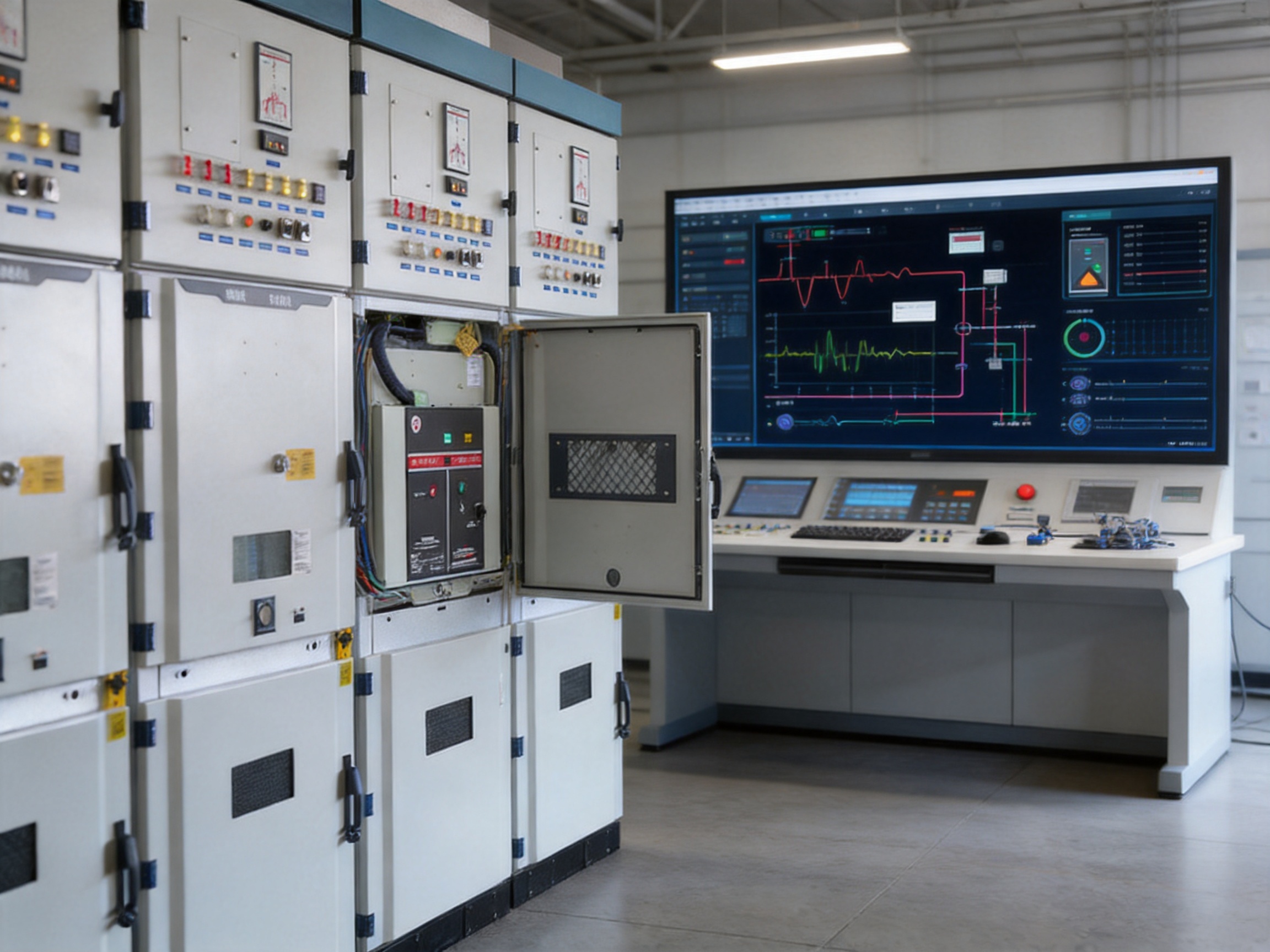
The relay instrument compartment can accommodate intelligent measurement and control terminals, fault recorders, protection devices, communication equipment, and other secondary components. This arrangement provides space for future changes in protection philosophy or automation architecture without necessarily redesigning the primary cabinet.
A secondary grounding busbar runs through the instrument compartment and is suspended from the top. This arrangement leaves useful space for terminals and secondary wiring. Good secondary wiring organization is essential for reliable control, easier testing, and efficient troubleshooting. It also helps separate low-level control and communication circuits from power conductors.
Some configurations support connection to a power distribution automation system. This can enable remote measurement and remote signaling functions, depending on the selected devices, communication architecture, control system, and project requirements. Typical information may include breaker status, trolley position, earthing-switch status, current, voltage, power, protection trips, alarms, and fault records.
The secondary plug is interlocked with the trolley position. When the trolley is in the working position, the secondary plug is locked and cannot be removed. This prevents the secondary connection from being unintentionally disconnected while the main circuit is connected. It also improves the reliability of the relationship between the intelligent equipment and the primary switching device.
Such provisions are particularly useful for unattended or lightly attended distribution rooms. Remote monitoring cannot replace local safety procedures, but it can improve operational visibility, support faster fault analysis, and reduce unnecessary site visits. The exact level of automation should be selected according to the importance of the load, cybersecurity requirements, communication standards, maintenance policy, and facility control architecture.
11. Manufacturing Strengths and Quality-Oriented Production
The manufacturer behind this product has experience in communication cabinets, communication electronic equipment, and passive optical components, in addition to providing customized integrated solutions. Although the switchgear belongs to the electrical power distribution field, this broader manufacturing background is relevant because modern switchgear increasingly combines mechanical structures, electrical power components, secondary electronics, communication interfaces, and system-level integration.
Advanced manufacturing begins with controlled material selection. Aluminum-zinc-coated steel provides a suitable basis for enclosure production, while high-strength bolts and rivets support reliable structural assembly. CNC machine tools allow the manufacturer to process panels with consistent dimensions. Multiple bending processes create stiffness and accurate interfaces. Double-bending side panels improve cabinet strength while reducing visible joints and openings.
Manufacturing quality is also reflected in the treatment of small details. Shutter guide rails must align correctly with trolley travel. Primary contact assemblies must maintain appropriate contact pressure and positioning. Interlocks must engage at the correct trolley locations. Doors, panels, cable supports, and pressure-relief routes must be installed without interference. The secondary wiring area must provide sufficient room for orderly termination and future servicing.
A product designed for customized applications must also support configuration control. Rated current, short-circuit level, breaker type, trolley type, protection equipment, metering equipment, cable arrangement, heater requirements, electromagnetic locks, and automation interfaces may vary from project to project. A capable manufacturer must coordinate these variables so that the final assembly remains mechanically compatible, electrically compliant, and maintainable.
The company has operated since 1997 and maintains a sales network covering more than 20 countries and regions. Its stated emphasis on reliable quality, timely delivery, customized products, and long-term partnerships is important for projects where switchgear must be delivered together with technical documentation, configuration support, installation guidance, and after-sales service.
International project experience can also help a manufacturer understand different installation practices, documentation expectations, grid requirements, and procurement procedures. However, every project must still be checked against the standards and regulations applicable in the destination country. Local electrical codes, utility specifications, inspection requirements, and site conditions should be incorporated during engineering and ordering.
12. Installation, Commissioning, and Maintenance Considerations
Proper installation is necessary to obtain the safety and performance benefits of the switchgear. The foundation or supporting channel should be level and accurately positioned. Cabinets should be aligned and securely joined. The equipment should be connected to the protective earthing system according to the applicable design and installation standards.
Before energization, the primary circuit should be inspected for correct connection, cleanliness, insulation condition, contact alignment, and phase identification. Cable terminations should be checked for appropriate torque, stress control, clearances, and support. The cable compartment should be free of tools, loose hardware, packaging materials, and conductive debris.
The mechanical operating sequence should be tested without energization. Personnel should confirm that the trolley moves correctly between working, testing, and disconnected positions. The circuit breaker should not be movable when closed. The earthing switch should be operable only under the correct trolley conditions. Rear doors and lower doors should respond correctly to the grounding-switch state.
The secondary circuit should be checked for correct wiring, terminal identification, insulation, polarity, control voltage, and communication function. Protection relays and measurement devices should be tested according to the protection coordination study and commissioning plan. The position interlock of the secondary plug should also be verified.
Routine maintenance may include visual inspection, cleaning, checking for signs of overheating or corrosion, mechanical operation tests, contact inspection, lubrication where specified, heater and thermostat checks, interlock verification, and review of event or fault records. Maintenance intervals should be based on the operating environment, switching frequency, fault history, manufacturer recommendations, and the criticality of the connected load.
Maintenance personnel must follow approved isolation, lockout, verification, and grounding procedures. A withdrawn trolley does not by itself prove that every part of the cabinet is de-energized. Incoming circuits, busbars, control supplies, auxiliary supplies, and stored mechanical or electrical energy must be identified and controlled before work begins.
13. Standards and Compliance Framework
The supplied product information identifies several Chinese national, industry, and international standards related to the design, testing, packaging, and application of the switchgear.
GB/T 3906-2020 addresses AC metal-enclosed switchgear and controlgear for rated voltages from 3.6 kV to 40.5 kV. GB/T 11022-2020 specifies common technical requirements for high-voltage AC switchgear and controlgear. GB/T 7354-2018 covers high-voltage testing techniques and partial discharge measurement.
DL/T 404-2018 addresses AC metal-enclosed switchgear and controlgear within the 3.6 kV to 40.5 kV range. DL/T 593-2016 provides common technical requirements for high-voltage switchgear and controlgear. DL/T 402-2016 applies to high-voltage AC circuit breakers, while GB/T 3804-2017 covers high-voltage AC load switches within the relevant voltage range.
GB/T 191-2008 concerns packaging and storage pictorial marking. The product information also refers to IEC 298 for AC metal-enclosed switchgear and control equipment above 1 kV and up to 50 kV. Project teams should verify the current edition and exact applicability of each standard before placing an order or approving a design.
Compliance should be demonstrated through the appropriate type tests, routine tests, inspection records, certificates, technical drawings, and commissioning documentation. The standards framework should be considered together with local regulations and the requirements of the end user, utility, consultant, or authority having jurisdiction.
14. Selecting the Correct Configuration
Although the base product is rated at 12 kV, the correct configuration depends on the complete electrical system. Engineers should begin with the system voltage, frequency, short-circuit level, continuous load current, transformer capacity, cable arrangement, protection philosophy, and expected switching duty.
The rated current should be selected with attention to normal loading, emergency loading, future expansion, thermal conditions, and the temperature-rise performance of the complete assembly. Selecting a current rating only from the present load may leave insufficient capacity for future modifications. Conversely, excessive oversizing can increase cost and physical dimensions without providing a meaningful operational benefit.
The short-circuit breaking current must be coordinated with the calculated fault current at the installation point. The selected peak withstand and short-time withstand ratings must also match the system fault duration and protection-clearing time. Internal arc classification should be evaluated in relation to the room layout, operator access, pressure-relief direction, and risk assessment.
Project teams should define whether each panel requires a circuit breaker trolley, metering trolley, isolation trolley, or another approved arrangement. Secondary requirements should include protection relays, measurement devices, fault recording, remote signaling, communication interfaces, electromagnetic locking, heaters, and auxiliary power supplies.
Environmental conditions must be confirmed before final design approval. Altitude above 1000 meters, unusually low temperatures, high humidity, salt exposure, industrial pollution, dust, vibration, and unusual seismic conditions can require changes to insulation, heating, enclosure construction, or mechanical design.
15. Typical Benefits for Facility Owners and Operators
Facility owners benefit from the equipment’s ability to combine safety, maintainability, and future expansion potential. The withdrawable trolley can reduce the disruption associated with breaker maintenance. Modular trolley interchangeability can simplify spare-parts management. Independent compartments can improve inspection and fault containment. Automatic shutters and interlocks can reduce exposure to live parts and incorrect operating sequences.
Operators benefit from clear trolley positions, controlled screw-driven movement, accessible control equipment, and the possibility of remote measurement and signaling. Maintenance personnel benefit from the rotating instrument beam, ample cable space, removable trolleys, and reserved interfaces for intelligent devices.
System designers benefit from a range of current ratings and short-circuit capabilities. Integrators benefit from the available secondary space and automation interfaces. Project owners seeking long-term modernization can deploy a suitable basic configuration initially while retaining the option to add advanced monitoring or control equipment later, provided that the original design reserves the necessary space and interfaces.
These advantages can contribute to lower lifecycle risk. Lifecycle value is not determined only by purchase price. It also includes installation time, commissioning effort, spare-parts requirements, outage duration, inspection accessibility, fault diagnosis, energy losses at connections, and the ability to adapt to future operating requirements.
16. Q&A
Q1: What is the main purpose of this indoor AC metal-clad withdrawable switchgear?
It is used in medium-voltage AC distribution systems for receiving, distributing, controlling, measuring, and protecting electrical energy. It can be installed in substations, power plants, industrial facilities, civil buildings, municipal installations, hotels, offshore platforms, and other indoor electrical distribution environments.
Q2: What is the rated voltage of the equipment?
The listed rated voltage is 12 kV. The equipment belongs to the medium-voltage switchgear category and is designed according to the applicable requirements for this voltage class.
Q3: What rated current options are available?
The rated current range is 630 A to 4000 A. The correct rating should be selected according to continuous load, future expansion, thermal conditions, cable configuration, and system design requirements.
Q4: What does “withdrawable” mean?
It means that the circuit breaker or other functional unit is mounted on a movable trolley. The trolley can be positioned in working, testing, or disconnected positions and can be removed from the cabinet with a dedicated transfer cart for maintenance or replacement.
Q5: How does the equipment help prevent operating errors?
The five-prevention interlocking system restricts unsafe sequences. For example, the trolley cannot be moved while the circuit breaker is closed, the earthing switch can operate only when the trolley is in the test or disconnected position, and rear access doors remain locked when the grounding switch is open. Some configurations can also include electromagnetic locks.
Q6: How are live primary contacts protected when the trolley is withdrawn?
Automatic shutters close over the static contact boxes when the trolley is withdrawn. This helps prevent personnel from accidentally touching live primary contacts during inspection or maintenance.
Q7: Can the switchgear accommodate multiple cables per phase?
Yes. The cable compartment provides sufficient space for multiple single-core cables connected in parallel on each phase, subject to the approved cable arrangement, termination design, and applicable installation requirements.
Q8: Can the switchgear be connected to a distribution automation system?
Some models support connection to a power distribution automation system. The instrument compartment can accommodate intelligent measurement and control terminals, fault recorders, and other secondary equipment for remote measurement and remote signaling.
Q9: Is the switchgear suitable for humid indoor environments?
It is designed for the specified indoor humidity conditions, with an average daily relative humidity of up to 95% and an average monthly relative humidity of up to 90%. Heaters can be installed in the circuit breaker and cable compartments to reduce condensation and corrosion. Site conditions should be reviewed during ordering.
Q10: What standards are referenced for the product?
The supplied information references GB/T 3906-2020, GB/T 11022-2020, GB/T 7354-2018, DL/T 404-2018, DL/T 593-2016, DL/T 402-2016, GB/T 3804-2017, GB/T 191-2008, and IEC 298. The applicable edition and compliance documentation should be confirmed for each project.
Q11: What makes the cabinet construction different from a basic enclosure?
The cabinet uses aluminum-zinc-coated steel, CNC processing, multiple precision bending operations, double-bent side panels, and riveted or high-strength bolted assembly. The design avoids unnecessary exposed screws and clearance holes, improving strength, appearance, corrosion resistance, and serviceability.
Q12: What should be confirmed before ordering?
The buyer should confirm rated current, short-circuit level, breaker and trolley type, cable quantity and termination arrangement, protection and metering requirements, control voltage, automation interfaces, heater requirements, electromagnetic locks, environmental conditions, altitude, installation dimensions, and applicable standards.
17. Conclusion
The indoor AC metal-clad withdrawable switchgear provides a comprehensive solution for medium-voltage power distribution. Its value comes from the coordinated performance of many elements: a strong aluminum-zinc-coated cabinet, CNC-based manufacturing, four independent compartments, automatic shutters, internal pressure-relief channels, a five-prevention interlocking system, modular withdrawable trolleys, ample cable space, accessible secondary equipment, and intelligent upgrade interfaces.
With a 12 kV rated voltage, current options from 630 A to 4000 A, short-circuit breaking capabilities up to 40 kA, and an internal arc classification available for the relevant fault levels, the product can be adapted to a wide range of power distribution projects. Its maintenance-oriented structure can help reduce replacement time, while its safety features support controlled operation and improved protection against accidental access to energized components.
The manufacturing approach is equally important. Consistent CNC processing, precision bending, high-strength assembly, modular design, and attention to mechanical interfaces provide a foundation for reliable service. The manufacturer’s broader experience in communication equipment, optical components, customized products, and integrated solutions also supports the development of switchgear that can accommodate modern monitoring and automation requirements.
For facility owners, engineering consultants, system integrators, and electrical contractors, the equipment offers a balanced combination of safety, reliability, maintainability, configurability, and future-readiness. Final performance depends on correct selection, professional installation, commissioning, periodic maintenance, and compliance with the applicable standards and site requirements.
References
GB/T 3906-2020, AC Metal-Enclosed Switchgear and Controlgear for Rated Voltages from 3.6 kV to 40.5 kV.
GB/T 11022-2020, Common Technical Requirements for High-Voltage AC Switchgear and Controlgear.
GB/T 7354-2018, High-Voltage Testing Techniques and Partial Discharge Measurement.
DL/T 404-2018, AC Metal-Enclosed Switchgear and Controlgear for Rated Voltages from 3.6 kV to 40.5 kV.
DL/T 593-2016, Common Technical Requirements for High-Voltage Switchgear and Controlgear.
DL/T 402-2016, High-Voltage AC Circuit Breakers.
GB/T 3804-2017, High-Voltage AC Load Switches.
GB/T 191-2008, Packaging and Storage Pictorial Marking.
IEC 298, AC Metal-Enclosed Switchgear and Control Equipment for Rated Voltages Above 1 kV and Up to 50 kV.
Manufacturer-provided product specifications for 12 kV indoor AC metal-clad withdrawable switchgear.
Product: Indoor Ac Metal-Clad Withdrawable Switchgear
PREV:Factory-Prepared Quick Connectors for Reliable Fiber Termination and Network Modernization
NEXT:Outdoor SMC Fiber Optic Distribution Boxes for High-Capacity Access Networks
NEXT:Outdoor SMC Fiber Optic Distribution Boxes for High-Capacity Access Networks
Interested in cooperation or have questions?
Related products
-
-
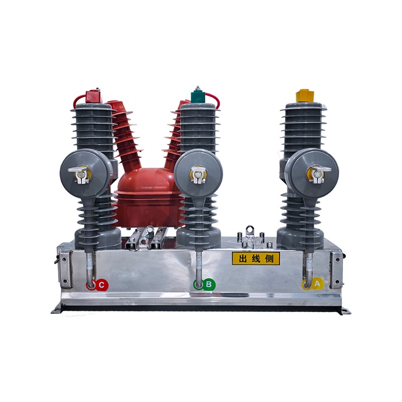
Product Overview: The ZW□-12/T630-25 outdoor high-voltage AC vacuum circuit breaker is a key device designed for 12 kV overhead distribution lines. By deeply integrating the primary switching unit wi...
See Details -
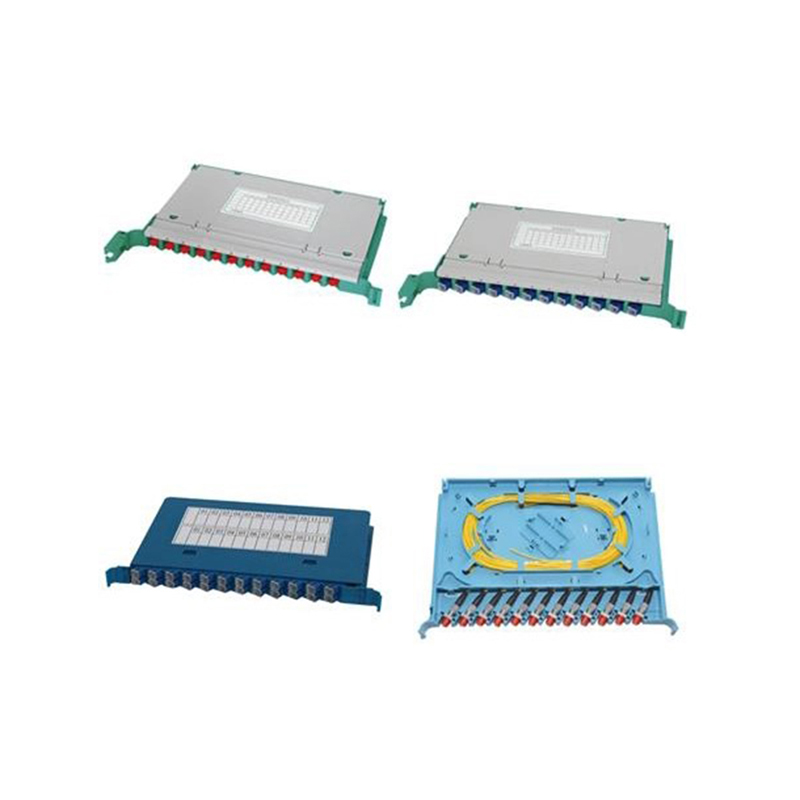
Application:It is extensively used as optical cable splicing and distribution unit in the OMDF, ODF, OCC and outdoor cabinet. Features:1. Splice Module can be used for fiber splicing, fiber distributi...
See Details -
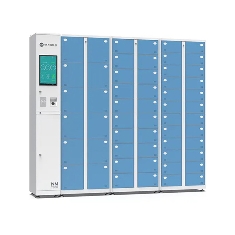
Product Definition:The Intelligent Geng Shoe Box is an advanced storage and management solution for hospitals, operating rooms, and clean zones. It enables automated issuance and collection of shoes a...
See Details
Ready to Get started ? Contact Us Now !

Product.
Contact Details.
-
 +86 13958188250
-
 +86 13958188250
-
 [email protected]
-
 AUDIT Email:[email protected]
- Wanma Industrial Park Taihu Yuan Town Lin'an District Hangzhou City China.
QR Code

Copyright © Wanma Technology Co., Ltd. All Rights Reserved.
Privacy
Custom Ethernet Optical Network Railway Transit Equipments Suppliers
