

 English
 Français
 Español
 Português
 عربى





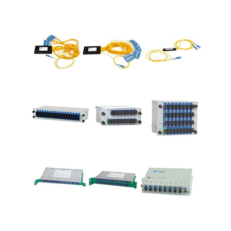

Application:It is suitable for the connection of Bow-type cables and is mainly used in optical fiber termination box, optical fiber distribution box, Household intelligent box, optical fiber socket-bo...
See DetailsQuick Connector Solutions for Reliable Fiber Installation and Network Modernization
Content
- 1 1. The Role of Quick Connectors in Fiber Networks
- 2 2. Product Overview
- 3 3. Optical Performance and Connection Stability
- 4 4. Installation Efficiency and Field Convenience
- 5 5. Hot-Melt Installation Technology
- 6 6. Applications in Communication Infrastructure
- 7 7. Advantages Compared with Conventional Field Termination
- 8 8. Manufacturing Strengths Supporting Product Quality
- 9 9. Quality and Installation Management
- 10 10. Applications in Ethernet and 5G FTTH Modernization
- 11 11. Applications in Railway and Urban Transit Systems
- 12 12. Customization and Project Support
- 13 13. Procurement Considerations
- 14 14. Recommended Installation Workflow
- 15 15. Q&A
- 15.1 Q1: What type of cable is the Fiber Solution Quick Connector designed for?
- 15.2 Q2: Where can the connector be used?
- 15.3 Q3: What is the stated insertion loss?
- 15.4 Q4: What is the return-loss specification?
- 15.5 Q5: Can the connector be installed more than once?
- 15.6 Q6: What tools are needed for basic installation?
- 15.7 Q7: Why is factory grinding important?
- 15.8 Q8: Is hot-melt installation completely independent of equipment quality?
- 15.9 Q9: Can the connector support network renovation?
- 15.10 Q10: What should customers confirm before purchasing?
- 15.11 Q11: What manufacturing strengths support the product?
- 15.12 Q12: Is the connector suitable for every outdoor or industrial environment?
- 16 16. Conclusion
- 17 References
- 18 Product: Fiber Solution-Quick Connector
Modern communication networks depend on optical fiber connections that are fast to install, mechanically stable, and consistent in optical performance. As Ethernet networks, fiber-to-the-home deployments, railway communication systems, data centers, and intelligent building infrastructures continue to expand, installers need connection technologies that reduce labor time without compromising signal quality. The Fiber Solution Quick Connector is designed to address these requirements by combining factory-prepared optical performance with practical field installation.
This connector is suitable for Bow-type cables and is intended for use in optical fiber termination boxes, optical fiber distribution boxes, household intelligent boxes, optical fiber socket boxes, and optical distribution frame renovation projects. It can also be used when installers need to set or modify patch cord lengths in a new optical distribution frame. Its design supports both rapid field work and stable network operation, making it a useful component for new installations, maintenance activities, and modernization programs.
The product is manufactured and supplied by Wanma Technology Co., Ltd., a company established in 1997 and focused on communication cabinets, communication electronic equipment, and passive optical components. With experience serving Ethernet networks, optical communication networks, central equipment rooms, high-speed railway systems, and urban rail transit systems, the company combines product manufacturing with application-oriented communication solutions.
The following article explains the product’s structure, working principles, installation benefits, optical characteristics, application areas, quality considerations, and the manufacturing strengths that support its use in demanding communication environments.
1. The Role of Quick Connectors in Fiber Networks
Fiber installation traditionally requires several operations, including cable preparation, fiber cleaving, connector assembly, polishing, inspection, and testing. These operations can require specialized equipment and trained technicians. They may also introduce variations between individual connections, particularly when work is performed in confined spaces, under time pressure, or in locations where a complete workshop setup is unavailable.
A quick connector simplifies this process by providing a pre-assembled connection interface that can be installed at the worksite with fewer tools. Instead of performing every connector preparation procedure manually, the installer prepares the Bow-type cable, positions the fiber correctly, and completes the connector assembly according to the product’s installation method.
The Fiber Solution Quick Connector is particularly useful where rapid deployment and predictable performance are important. Examples include residential fiber connections, distribution box expansion, intelligent building projects, maintenance work, and optical distribution frame reconstruction. In these situations, reducing the number of installation steps can help shorten service interruptions and improve project productivity.
Quick connectors are not simply labor-saving accessories. Their value depends on the relationship between mechanical retention, fiber alignment, end-face quality, environmental stability, and installation repeatability. A connector that is fast to install but inconsistent in optical performance may create additional troubleshooting work. For this reason, the Fiber Solution Quick Connector emphasizes factory treatment of the fiber end face, repeated installation capability, and a controlled connection structure.
2. Product Overview
The Fiber Solution Quick Connector is designed for the connection of Bow-type cables. It can be integrated into several types of passive optical infrastructure, including optical fiber termination boxes, optical fiber distribution boxes, household intelligent boxes, optical fiber socket boxes, and optical distribution frames.
Its principal purpose is to create a practical termination point between the incoming fiber cable and the equipment, adapter, or patching system connected to it. Because the connector can be installed at the project site, installers do not always need to prepare every cable length in advance. This is valuable when actual routing distances differ from initial drawings or when a network requires later adjustment.
The connector is available in a hot-melt type configuration. This installation approach uses heat to complete the connector assembly at the site. When suitable equipment is used and the installation procedure is correctly controlled, hot-melt assembly can provide stable performance and reliable mechanical retention.
The product’s stated typical optical characteristics include insertion loss below 0.5 dB, with a typical value of approximately 0.3 dB, and return loss above 45 dB for UPC versions. These figures support the connector’s use in many access, distribution, and communication network applications. Actual results can depend on fiber condition, installation quality, adapter condition, test method, and environmental factors.
| Item | Product Information | Practical Significance |
|---|---|---|
| Applicable cable | Bow-type cable | Supports common indoor and access-network cable termination requirements |
| Primary applications | Termination boxes, distribution boxes, intelligent boxes, socket boxes, and ODF renovation | Suitable for residential, commercial, industrial, and communication-room projects |
| Installation approach | Quick installation with limited tools; hot-melt version available | Helps reduce field labor and simplify deployment |
| Insertion loss | Less than 0.5 dB; typical value approximately 0.3 dB | Supports efficient optical transmission when properly installed |
| Return loss | Greater than 45 dB for UPC | Helps control reflected optical power in the connection |
| Reinstallation | Can be installed repeatedly more than three times with stable performance | Useful during adjustment, maintenance, and troubleshooting |
| Basic field tools | Wire stripper and cutting knife for the basic installation process | Reduces dependence on a large set of specialized tools |
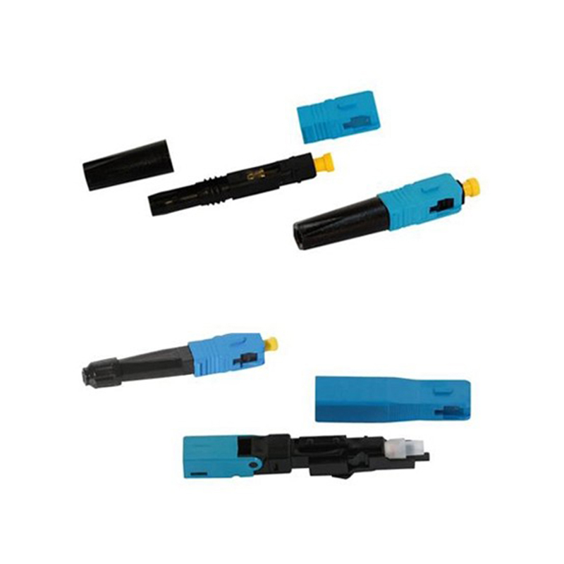
Fiber Solution-Quick Connector
3. Optical Performance and Connection Stability
3.1 Factory-Prepared Fiber End Face
One of the product’s most important advantages is that the fiber end face is ground in the factory. End-face geometry has a direct influence on insertion loss, return loss, and connection consistency. If the end face is uneven, contaminated, chipped, or improperly polished, the two optical surfaces may not align efficiently. This can increase signal attenuation and reflection.
Factory grinding provides a controlled preparation environment. Compared with fully manual polishing at the installation site, factory treatment can reduce variation caused by differences in technician technique, tool condition, workplace cleanliness, and polishing time. It also allows the manufacturer to establish a repeatable process for preparing the optical interface before the product reaches the installer.
This does not eliminate the need for careful field handling. The connector and fiber must still be kept clean, protected from dust, and installed according to the correct procedure. However, factory-prepared end-face treatment moves a critical precision operation away from uncertain field conditions and into a controlled manufacturing process.
3.2 Insertion Loss
Insertion loss represents the optical power lost when a component is introduced into a fiber link. Lower insertion loss generally provides more available power for the rest of the network and contributes to a healthier optical budget. The stated insertion loss for the Fiber Solution Quick Connector is below 0.5 dB, with a typical value of approximately 0.3 dB.
For access networks and short distribution links, this performance can be especially useful because the connector can preserve a larger portion of the available optical budget for splitters, adapters, cable length, splices, and other passive components. In larger networks, the accumulated effect of many connection points makes the performance of each individual connector important.
Actual insertion loss is influenced by several factors. These include the quality of the fiber cleave, the cleanliness of the end face, the accuracy of fiber positioning, adapter condition, cable preparation, and test equipment calibration. Therefore, the stated product specification should be understood as a manufacturing and design target under appropriate installation and testing conditions.
3.3 Return Loss and UPC Performance
Return loss describes the reduction of reflected optical power caused by a connection. A higher return-loss value generally indicates lower reflection. The product information specifies return loss above 45 dB for UPC versions. This characteristic can be valuable in communication systems where reflections may affect transmission stability, especially in links using sensitive optical transmitters or high-speed signaling formats.
UPC treatment is commonly associated with a refined physical contact surface that reduces reflection compared with a basic flat interface. The final performance depends on the connector configuration, mating adapter, cleanliness, and condition of both connected end faces. Proper inspection and cleaning remain essential during installation and maintenance.
By combining factory end-face preparation with a controlled connector structure, the product is designed to offer a more predictable optical interface than a connection assembled entirely through variable field polishing. This is one of the main ways the product can distinguish itself from low-cost alternatives that focus only on initial installation speed.
4. Installation Efficiency and Field Convenience
4.1 Reduced Tool Requirements
The product is designed to simplify the installation process. The basic installation requires a wire stripper and cutting knife, together with the relevant procedures and any equipment required for the hot-melt version. Compared with conventional connector assembly that may require multiple specialized tools, this approach can make field work more accessible.
Fewer tools can provide several operational benefits. Technicians can carry lighter equipment to residential buildings, utility corridors, railway facilities, or crowded communication rooms. The risk of forgetting a specialized tool is reduced. Training requirements may also be easier to manage because installers can focus on cable preparation, fiber positioning, and connector assembly rather than a long sequence of polishing operations.
Tool reduction should not be confused with the elimination of technical skill. Fiber installation still requires attention to stripping length, fiber cleanliness, bending radius, alignment, and mechanical locking. The advantage is that the product concentrates the installation task around a smaller number of controlled actions.
4.2 Repeated Installation Capability
The connector can be installed repeatedly more than three times while maintaining stable performance, according to the supplied product information. This feature is valuable when a cable must be repositioned, a termination box is reorganized, or an installer needs to correct an alignment issue during commissioning.
In practical projects, the first installation is not always the final installation. Cable routing may change after other equipment is placed. A distribution box may need to be reorganized to improve bend management. A patch cord may need to be adjusted to accommodate a revised rack layout. Reinstallation capability provides greater flexibility in these situations and can reduce material waste.
Repeated installation must still be performed carefully. The fiber end face should remain clean, the mechanical components should not be forced, and the installer should follow the specified procedure each time. If a connector has been exposed to dust, moisture, excessive bending, or physical damage, it should be inspected before reuse.
4.3 Faster On-Site Deployment
A quick connector can shorten the time between cable arrival and network activation. This is useful in projects where many individual fiber endpoints must be completed, such as multi-dwelling residential buildings, office campuses, transportation facilities, and communication cabinets distributed across a large site.
Faster installation can improve productivity in two ways. First, a technician may complete more connection points during a work shift. Second, the project may require fewer return visits caused by incorrect pre-measured cable lengths or incomplete workshop preparation. The ability to establish or modify patch cord lengths at a new optical distribution frame further increases flexibility during commissioning.
For network operators, reduced installation time may also lower the duration of service migration or maintenance windows. This is particularly relevant when an existing optical distribution frame is being renovated and the work must be coordinated with active communication services.
5. Hot-Melt Installation Technology
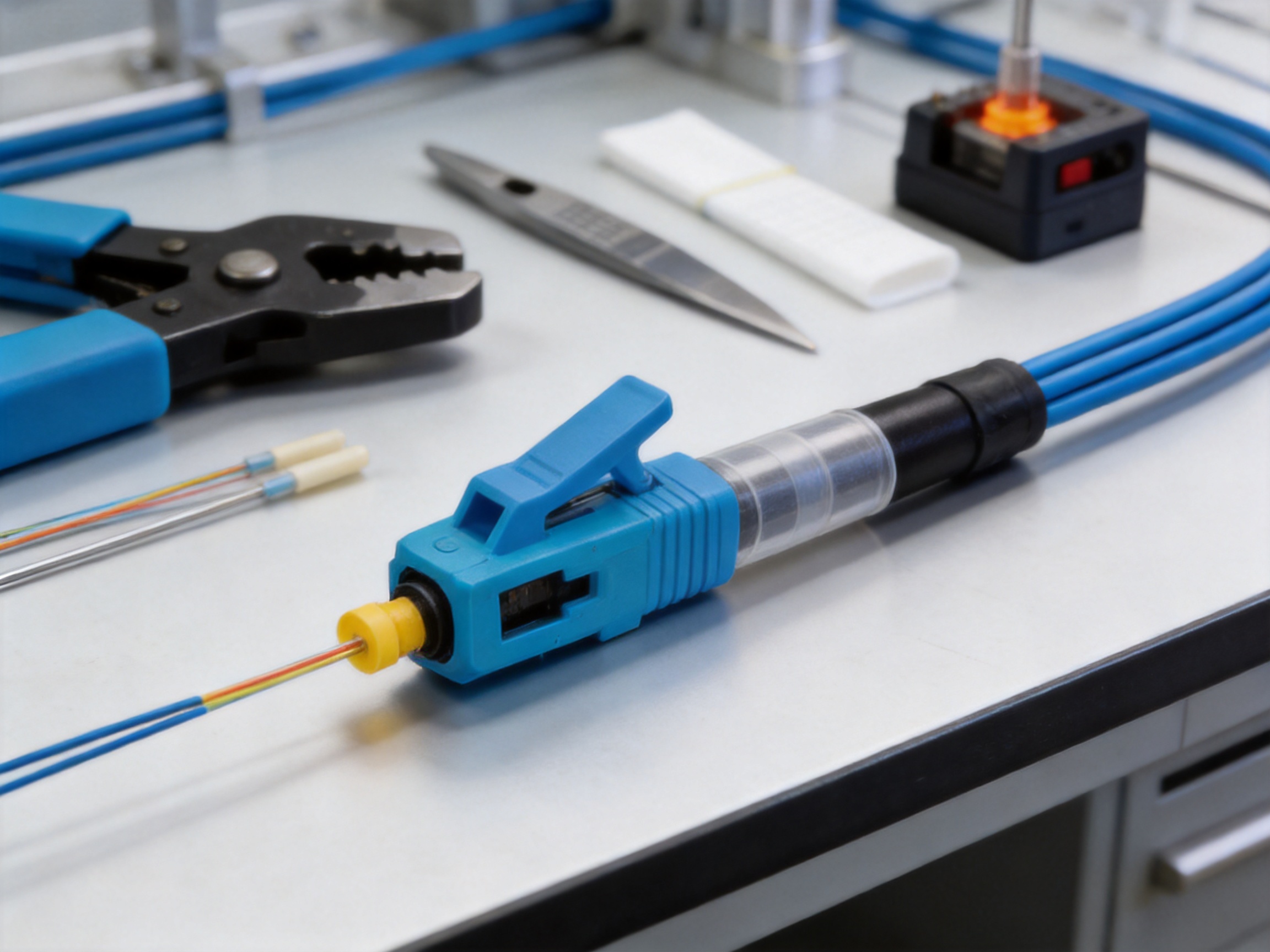
The hot-melt type quick connector is installed on site by hot-melting. This method uses controlled heat to complete the connector assembly and secure the prepared fiber within the connector structure. When the heating equipment is stable and the procedure is correctly followed, hot-melt installation can provide reliable and repeatable results.
5.1 Controlled Heat and Process Stability
The performance of a hot-melt connector depends partly on the stability of the equipment used to complete the installation. Temperature, heating duration, alignment, and cooling conditions all influence the final connection. If the equipment is poorly maintained or operated outside the required parameters, the connector may not achieve its expected mechanical or optical performance.
For this reason, hot-melt installation should be treated as a controlled process rather than an improvised field operation. Installers should use suitable equipment, verify that the equipment is operating correctly, and follow the manufacturer’s operating instructions. Periodic equipment inspection and maintenance can help reduce unnecessary losses caused by equipment instability or incorrect operation.
5.2 Reducing Human-Related Variation
Conventional field termination may be highly dependent on individual workmanship. The hot-melt approach can reduce some sources of variation by using a defined connector assembly method and a prepared optical interface. However, human factors remain important during stripping, cleaning, positioning, and equipment operation.
The product information specifically emphasizes the importance of equipment stability because unreliable equipment can cause unnecessary losses. This is a practical advantage of the product’s design philosophy: it recognizes that product performance is connected to the entire installation system, including tools, procedures, training, and quality inspection.
5.3 Maintenance and Field Repair
Hot-melt quick connectors can be useful for network repair because they allow technicians to complete a connection without transporting the cable to a distant workshop. In a railway station, central equipment room, or residential distribution box, a technician can prepare the cable and complete the termination close to the actual point of use.
This can reduce the need to replace long cable sections simply because one endpoint has been damaged. It may also reduce the time required to restore service after a maintenance event. As with all optical repair work, the repaired connection should be inspected and tested before being returned to service.
6. Applications in Communication Infrastructure
6.1 Optical Fiber Termination Boxes
Optical fiber termination boxes provide an organized location for terminating, protecting, and managing incoming and outgoing fibers. The Fiber Solution Quick Connector can be used to create termination points inside these boxes, helping installers complete connections according to the actual cable routing and available space.
In compact termination boxes, installation convenience is important because technicians may have limited room for cable preparation. A connector that requires fewer tools and supports field assembly can make it easier to work within a structured enclosure while maintaining appropriate fiber routing and bend control.
6.2 Optical Fiber Distribution Boxes
Distribution boxes are used in access networks to organize fiber connections between feeder cables, distribution cables, and drop cables. The product’s suitability for Bow-type cables makes it relevant to many indoor and last-mile distribution scenarios.
Distribution points may be expanded or reorganized as subscriber numbers increase. The ability to install or reinstall the connector can assist with incremental network growth. It can also help technicians manage changes without replacing the entire distribution assembly.
6.3 Household Intelligent Boxes
Household intelligent boxes integrate communication, security, control, and other low-voltage services within residential buildings. Fiber connections in these boxes often need to be compact, organized, and easy to maintain. The quick connector can support fiber termination in residential communication layouts where installation time and space efficiency are important.
In new construction, the connector can help installers set the final connection after the interior cable path has been completed. In renovation work, it can help adapt an existing fiber route to updated network equipment or a changed household layout.
6.4 Optical Fiber Socket Boxes
Optical fiber socket boxes provide a user-side interface for fiber access services. They must accommodate cable entry, fiber management, protection, and connection to the customer premises equipment. A quick connector can support efficient termination during initial service activation or later repair.
Because residential service work often takes place in occupied buildings, installers benefit from solutions that minimize workspace requirements and avoid lengthy preparation procedures. Properly installed, the connector contributes to an orderly and serviceable fiber endpoint.
6.5 Optical Distribution Frame Renovation
Optical distribution frames are central points for fiber organization in equipment rooms and network facilities. Renovation projects may involve replacing outdated components, reorganizing fiber routes, or setting patch cord lengths for a newly installed frame.
The Fiber Solution Quick Connector is designed for setting patch cord length in new optical distribution frames. This provides flexibility when the final rack arrangement is not fully determined until equipment installation has begun. It can also help reduce excess cable length and improve the appearance and manageability of the frame.
7. Advantages Compared with Conventional Field Termination
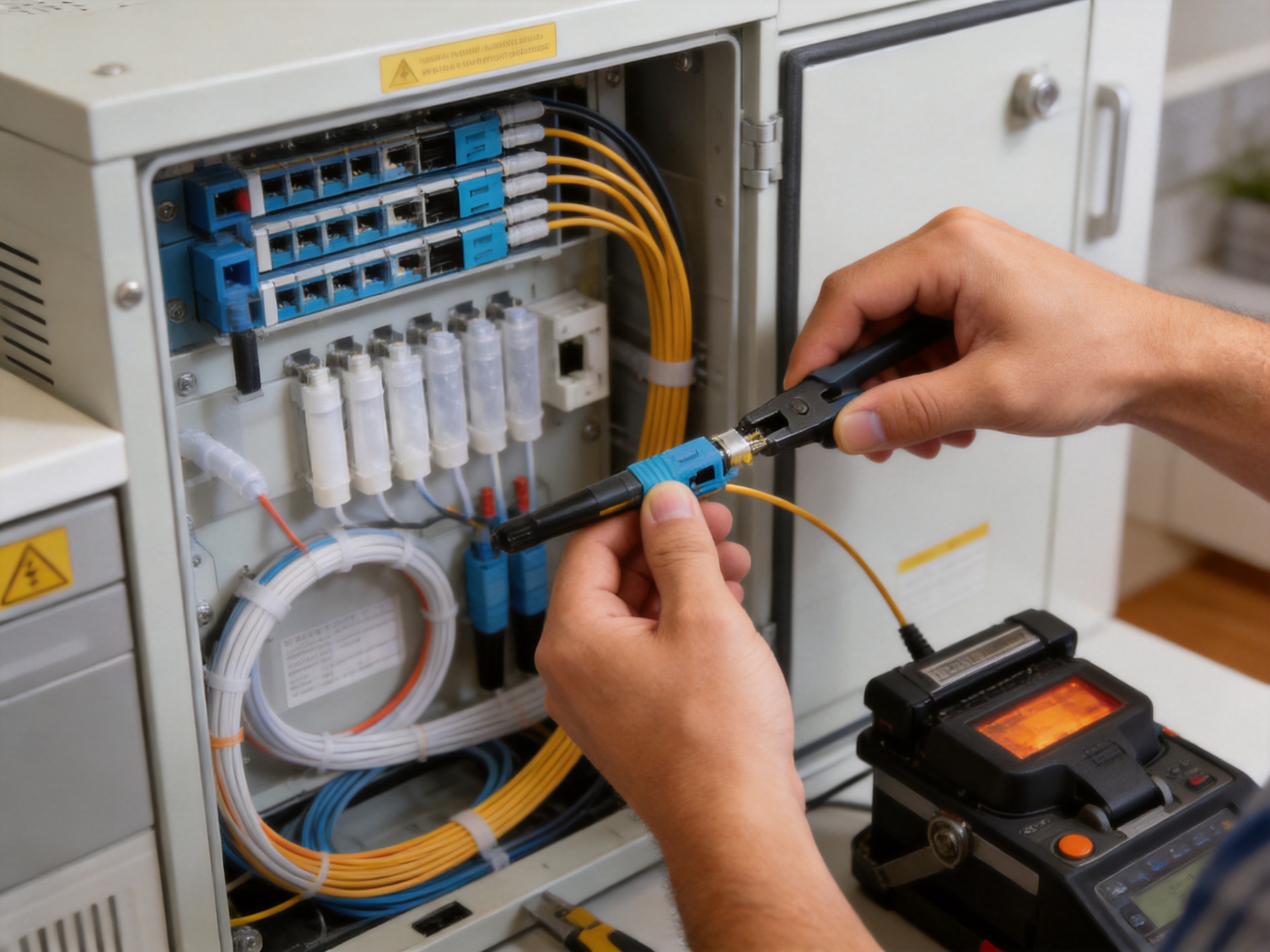
The most significant competitive advantage of a quick connector is the balance between field convenience and controlled optical performance. Conventional field termination can provide flexibility, but it may involve more tools, more preparation steps, and greater dependence on technician skill. A factory-prepared quick connector shifts part of the precision work into the manufacturing environment.
| Evaluation Area | Quick Connector Approach | Potential Benefit Compared with Fully Manual Field Termination |
|---|---|---|
| Optical end-face preparation | Factory-ground fiber end face | More consistent preparation under controlled production conditions |
| Field equipment | Limited basic tools, with suitable hot-melt equipment when required | Lower equipment burden and easier mobility |
| Installation time | Designed for rapid on-site assembly | Faster completion of multiple endpoints |
| Correction during installation | Repeated installation capability | More flexibility when routing or positioning must be adjusted |
| Optical targets | Insertion loss below 0.5 dB; typical approximately 0.3 dB | Supports efficient use of the optical power budget |
| Reflection control | Return loss above 45 dB for UPC | Helps limit optical reflection when properly connected |
| Project adaptability | Suitable for boxes, sockets, ODF renovation, and cable-length adjustment | Useful across new construction, maintenance, and modernization |
Compared with low-cost connectors that may provide limited process control, the product’s factory grinding and specified optical characteristics offer a stronger basis for predictable performance. Compared with permanent or less flexible termination methods, its repeatable installation capability offers more room for adjustment. Compared with solutions that require extensive field polishing, its streamlined tool requirement can reduce the burden on installers.
These advantages are especially relevant when network owners evaluate total installation cost rather than unit purchase price alone. Labor time, troubleshooting, rework, tool transportation, service interruption, and material waste can all affect the actual cost of a fiber deployment. A connector that supports faster and more consistent installation may provide value over the full project lifecycle.
8. Manufacturing Strengths Supporting Product Quality
8.1 Experience in Passive Optical Components
Wanma Technology Co., Ltd. was established in 1997 and specializes in communication cabinets, communication electronic equipment, and passive optical components. This product background is important because quick connectors operate within a broader passive optical system. Their performance must be considered alongside cabinets, boxes, adapters, cable management structures, and optical distribution equipment.
Experience across related product categories can help a manufacturer understand how connectors are installed and used in real network environments. It also supports the development of products that are compatible with practical enclosure layouts and field maintenance requirements.
8.2 Controlled Factory Processes
The factory-ground fiber end face is a direct example of how manufacturing control supports field performance. Precision preparation, controlled assembly, component inspection, and consistent packaging are important stages in producing a dependable connector. The objective is to ensure that each product reaches the installer with the critical optical interface prepared before deployment.
In addition to end-face treatment, a robust manufacturing process should manage material selection, dimensional accuracy, mechanical retention, assembly cleanliness, and product inspection. While individual project requirements may differ, these process areas form the foundation of repeatable passive optical component production.
The company’s ability to develop and manufacture its own branded products allows it to coordinate product design, production, quality management, and customer feedback. This can be more responsive than relying exclusively on unrelated third-party components, particularly when customers need customized configurations or integrated communication solutions.
8.3 Integrated Solution Capability
Wanma Technology is not limited to a single product category. Its portfolio includes communication cabinets, communication electronic equipment, and passive optical components. This broader capability allows the company to support projects that require multiple parts of a communication infrastructure rather than one isolated connector.
For network contractors and system integrators, integrated supply can simplify procurement and project coordination. A supplier that understands cabinets, optical distribution, and passive components may be better positioned to discuss how a connector should be used within a complete installation. It can also help customers identify suitable solutions for standard and customized applications.
8.4 Application Experience in Demanding Networks
The company’s products are used in Ethernet networks, optical communication networks, central equipment rooms, national high-speed railways, and urban rail transit systems. These environments place different requirements on communication equipment. Central equipment rooms prioritize organization and maintainability. Residential access networks prioritize installation efficiency and compactness. Railway and transit systems place strong emphasis on dependable infrastructure and disciplined maintenance.
Experience across these environments can strengthen product development by exposing the manufacturer to different installation conditions, operational priorities, and customer expectations. The result is a product approach that considers not only laboratory performance but also field usability.
9. Quality and Installation Management
Even a well-designed quick connector requires proper installation management. The following practices can help installers achieve stable results:
First, inspect the cable before preparation. The Bow-type cable should be free from crushing, excessive bending, cuts, and contamination. Damaged cable sections can compromise the connection regardless of connector quality.
Second, use the correct stripping method. Excessive force may damage the fiber or weaken the cable structure. Insufficient stripping may prevent the fiber from reaching the intended position inside the connector.
Third, keep all optical surfaces clean. Dust particles are extremely small but can create significant air gaps or scratches when trapped between mating end faces. Connectors should be protected from unnecessary exposure during installation.
Fourth, control fiber routing and bend radius. A connector may perform well at the end face while the cable experiences excessive stress immediately behind the connector. Proper slack management and bend control are therefore part of the complete installation.
Fifth, verify hot-melt equipment stability. Temperature and timing should remain within the required operating conditions. Equipment that produces inconsistent heat can lead to variation in mechanical or optical results.
Sixth, perform optical testing after installation when the project requires formal acceptance. Insertion-loss and return-loss measurements can help confirm the quality of the completed link and identify contamination, misalignment, or cable-related problems.
Finally, label and document the completed connection. Clear identification supports future maintenance, especially in distribution boxes and optical distribution frames containing many similar fiber paths.
10. Applications in Ethernet and 5G FTTH Modernization
Ethernet optical networks require scalable physical infrastructure. As bandwidth demand increases, many network operators are modernizing older copper or lower-capacity fiber arrangements. Quick connectors can support this work by making it easier to create, reorganize, and maintain optical termination points.
In fiber-to-the-home modernization, deployment efficiency is a major consideration. Service providers may need to connect large numbers of households while working in buildings with different cable routes and enclosure arrangements. A connector suitable for Bow-type cables and household intelligent boxes can help installers adapt to these variations.
5G-related modernization also requires dense and dependable fiber infrastructure. Although the connector itself is a passive component, it contributes to the physical layer that connects access equipment, distribution points, and transport facilities. The ability to adjust patch cord lengths and complete terminations in the field can support phased upgrades and network expansion.
As networks become more distributed, maintenance simplicity becomes increasingly important. A connection technology that can be installed with fewer tools and reinstalled during adjustment can help field teams manage a larger number of endpoints with fewer specialized resources.
11. Applications in Railway and Urban Transit Systems
Railway and urban transit communication networks support signaling, surveillance, passenger information, operations management, and other services. These systems often include communication rooms, trackside facilities, stations, control centers, and distributed equipment cabinets.
Fiber connections in these environments must be organized and maintainable. During a system expansion or equipment replacement, technicians may need to reconfigure optical distribution points without replacing long cable sections. The quick connector’s ability to support field installation and repeated adjustment can be beneficial in such projects.
Transit projects also involve strict scheduling. Work may need to be completed during limited maintenance windows or coordinated with construction milestones. A connector that reduces the number of field preparation steps can help teams use available work periods more efficiently.
Application suitability should always be evaluated against the project’s environmental, mechanical, fire-safety, and technical specifications. The connector is a component within a complete system, and the selected configuration should match the enclosure, cable type, optical interface, and applicable project standards.
12. Customization and Project Support
Communication infrastructure projects are rarely identical. Cable types, enclosure dimensions, adapter arrangements, fiber counts, patching requirements, and installation procedures may vary from one customer to another. A manufacturer that develops, produces, and markets its own products can provide a more direct path for discussing customized requirements.
Wanma Technology provides integrated solutions for customized products in addition to its standard communication equipment and passive optical components. This capability may be useful when a customer needs a connector solution coordinated with a communication cabinet, optical distribution box, or special project layout.
Customization should begin with a clear technical review. Important information includes the cable construction, required connector interface, optical polish type, available installation space, expected operating environment, quantity, test requirements, and delivery schedule. Early communication reduces the risk of selecting a product that fits one part of the system but not the complete installation.
Long-term supplier cooperation can also improve project continuity. When the same supplier understands a customer’s network architecture and purchasing requirements, future orders, replacement planning, and product standardization may become easier to manage.
13. Procurement Considerations
When selecting a quick connector, buyers should evaluate more than the advertised unit price. Optical performance, installation method, tool requirements, repeatability, cable compatibility, manufacturing control, and technical support all influence the product’s practical value.
Cable compatibility should be confirmed first. The Fiber Solution Quick Connector is intended for Bow-type cables, so the cable construction and dimensions should match the connector’s application requirements. The optical interface should also be verified, including the required polish type and mating adapter.
Next, buyers should review optical specifications. Insertion loss below 0.5 dB and typical performance near 0.3 dB can support many network applications, but project acceptance criteria may be stricter. Return loss above 45 dB for UPC versions should be assessed alongside the requirements of the complete optical link.
Installation conditions are equally important. If field teams work in remote locations, a low tool requirement can provide a major operational advantage. If the project involves frequent repositioning, repeated installation capability may reduce waste and rework. For hot-melt versions, buyers should confirm equipment availability and training arrangements.
Quality documentation should be discussed before purchase. Depending on the project, customers may request inspection records, optical test data, packaging requirements, labeling, sample approval, or batch traceability. These requirements help ensure that delivered components can be accepted and managed within a formal network construction program.
14. Recommended Installation Workflow
Step 1: Confirm the Installation Point
Determine the exact location of the termination box, distribution box, socket box, or optical distribution frame connection. Confirm that the cable route provides sufficient working length and that the connector will not be exposed to unnecessary tension.
Step 2: Prepare the Work Area
Keep the work area clean and organized. Prepare the wire stripper, cutting knife, suitable hot-melt equipment where applicable, cleaning materials, inspection tools, and testing equipment. A clean work surface reduces the likelihood of contamination.
Step 3: Inspect and Prepare the Cable
Inspect the Bow-type cable for damage. Strip the cable carefully according to the installation procedure. Avoid sharp bends and protect the exposed fiber from contact with hard or contaminated surfaces.
Step 4: Position the Fiber
Place the fiber into the connector according to the specified alignment and insertion requirements. Ensure that the fiber reaches the correct position and that the cable jacket and strength elements are properly managed.
Step 5: Complete the Connector Assembly
For the hot-melt type, use stable and suitable equipment to complete the heating and assembly process. Maintain the required conditions and allow the connection to cool or set as instructed. Do not move or stress the connector prematurely.
Step 6: Inspect and Test
Inspect the finished connection and mating surfaces. Connect the component to the appropriate adapter and perform optical testing where required. Any abnormal loss or reflection should be investigated before the link is accepted.
Step 7: Secure and Document
Manage the cable bend radius, secure the connector in the enclosure, apply identification labels, and record the fiber path. Good documentation supports future maintenance and reduces the time required to locate individual connections.
15. Q&A
Q1: What type of cable is the Fiber Solution Quick Connector designed for?
It is designed for Bow-type cables. Cable compatibility should be confirmed before installation, including the cable dimensions and construction required by the selected connector configuration.
Q2: Where can the connector be used?
It is suitable for optical fiber termination boxes, optical fiber distribution boxes, household intelligent boxes, optical fiber socket boxes, and optical distribution frame renovation. It can also be used when setting patch cord lengths in a new optical distribution frame.
Q3: What is the stated insertion loss?
The stated insertion loss is below 0.5 dB, with a typical value of approximately 0.3 dB. Actual field results depend on installation quality, cleanliness, cable condition, adapter quality, and test conditions.
Q4: What is the return-loss specification?
The stated return loss is greater than 45 dB for UPC versions. Proper end-face cleanliness and correct mating are necessary to achieve stable optical performance.
Q5: Can the connector be installed more than once?
Yes. The product information states that it can be installed repeatedly more than three times with stable performance. Reinstallation should be performed carefully and only when the connector and fiber remain undamaged and clean.
Q6: What tools are needed for basic installation?
The basic installation process requires a wire stripper and cutting knife. The hot-melt type also requires appropriate hot-melt equipment. The exact tool arrangement should follow the manufacturer’s installation instructions and project requirements.
Q7: Why is factory grinding important?
Factory grinding provides a controlled method for preparing the fiber end face. It can reduce variation associated with manual field polishing and help support more consistent insertion-loss and return-loss performance.
Q8: Is hot-melt installation completely independent of equipment quality?
No. The performance of the hot-melt type depends partly on the stability of the equipment used during installation. Reliable heating conditions, correct operating procedures, and trained technicians are important for avoiding losses caused by equipment or process errors.
Q9: Can the connector support network renovation?
Yes. It is suitable for optical distribution frame renovation and for setting patch cord lengths in new optical distribution frames. Its field installation and repeated adjustment features can be useful when existing layouts are being reorganized.
Q10: What should customers confirm before purchasing?
Customers should confirm cable compatibility, connector interface, polish type, optical specifications, installation method, hot-melt equipment requirements, project quantity, testing requirements, packaging, labeling, and delivery schedule.
Q11: What manufacturing strengths support the product?
The supplier has specialized in communication cabinets, communication electronic equipment, and passive optical components since 1997. Its own product development and manufacturing capabilities, experience in optical communication networks, and integrated customized-solution services support the product’s use in broader communication infrastructure projects.
Q12: Is the connector suitable for every outdoor or industrial environment?
Application suitability depends on the complete product configuration and project requirements. Buyers should review environmental, mechanical, temperature, moisture, fire-safety, and enclosure specifications before using the connector in a specialized outdoor or industrial application.
16. Conclusion
The Fiber Solution Quick Connector provides a practical approach to Bow-type cable termination in access networks, communication rooms, residential fiber systems, railway communication infrastructure, and optical distribution frame modernization. Its principal advantages include factory-ground fiber end faces, insertion loss below 0.5 dB with a typical value of approximately 0.3 dB, return loss above 45 dB for UPC versions, reduced tool requirements, hot-melt installation, and repeated installation capability.
Compared with fully manual field termination, the product can help reduce installation complexity and variation. Compared with inflexible connection methods, it provides more room for adjustment during commissioning and maintenance. Compared with low-cost alternatives that may lack controlled end-face preparation, it offers a stronger foundation for predictable optical performance.
The product is also supported by the broader manufacturing and application experience of Wanma Technology Co., Ltd. Since its establishment in 1997, the company has developed communication cabinets, communication electronic equipment, passive optical components, and customized communication solutions for customers in multiple markets. Its experience in Ethernet networks, optical communication systems, high-speed railways, urban rail transit, and central equipment rooms provides a relevant foundation for understanding the practical requirements of fiber infrastructure.
For best results, the connector should be selected according to cable type, optical interface, enclosure design, environmental conditions, and project testing requirements. Installation teams should maintain cleanliness, use stable equipment, control fiber routing, and verify completed connections. When these factors are managed together, the quick connector can support faster deployment, easier maintenance, and dependable optical network modernization.
References
1. Product information supplied for the Fiber Solution Quick Connector, including application descriptions, installation features, insertion-loss data, return-loss data, and repeated-installation characteristics.
2. Company information supplied for Wanma Technology Co., Ltd., including corporate history, product categories, application markets, manufacturing capabilities, and customized-solution services.
3. International Electrotechnical Commission, optical fiber connector performance and testing principles.
4. Telecommunications industry guidance on fiber-optic installation, connector cleanliness, optical-loss measurement, and return-loss evaluation.
5. General engineering practices for optical distribution frames, fiber termination boxes, access networks, Ethernet infrastructure, and fiber-to-the-home deployment.
6. General maintenance practices for passive optical components in central equipment rooms, railway communication systems, and urban transit networks.
Product: Fiber Solution-Quick Connector
PREV:WM-1001-F023 Fiber Optic Distribution Box: A Practical Platform for Outdoor FTTH Access Networks
NEXT:Fiber Solution Optical Fiber Socket Box for Reliable FTTH, FTTO, and FTTB Connectivity
NEXT:Fiber Solution Optical Fiber Socket Box for Reliable FTTH, FTTO, and FTTB Connectivity
Interested in cooperation or have questions?
Related products
-
-
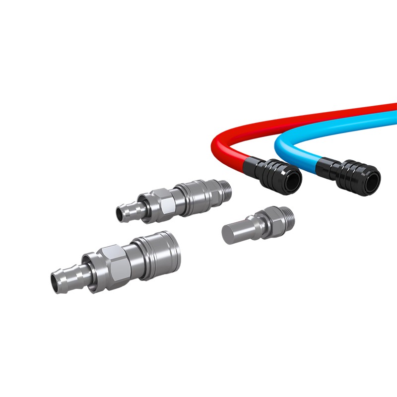
Product OverviewWM-UQD Liquid Cooling Quick Disconnect Coupling is a fluid connection component specifically designed for online maintenance of liquid cooling systems. Both the plug and socket are equ...
See Details -
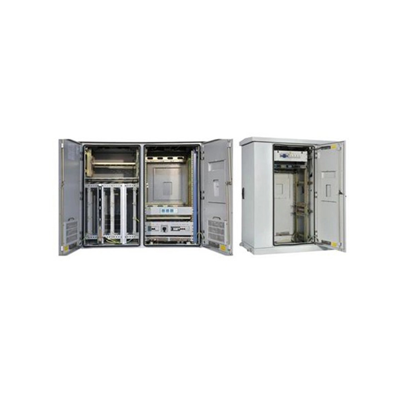
Application:It is used for the fixed network and broadband access, providing physical working environment and security system for the workstation in wired network. Features:•The cabinet is composed of...
See Details -
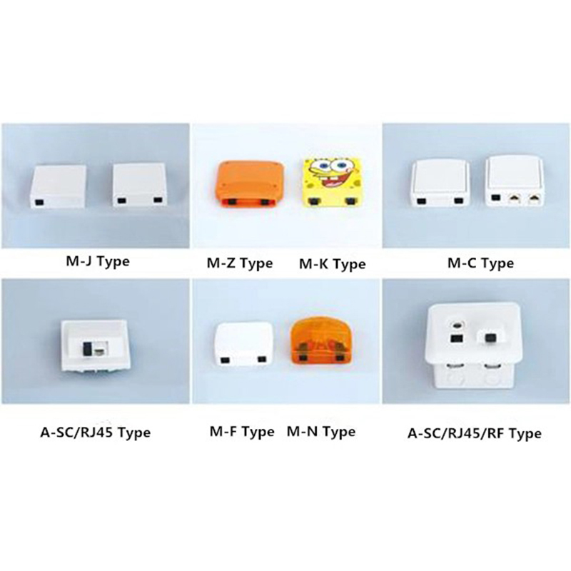
Application:It can be applied to FTTH, FTTO, FTTB applications and also has the functions of splicing, welding and installing connectors. Features:•Large variety; Full specification; Pleasing appearan...
See Details
Ready to Get started ? Contact Us Now !

Product.
Contact Details.
-
 +86 13958188250
-
 +86 13958188250
-
 [email protected]
-
 AUDIT Email:[email protected]
- Wanma Industrial Park Taihu Yuan Town Lin'an District Hangzhou City China.
QR Code

Copyright © Wanma Technology Co., Ltd. All Rights Reserved.
Privacy
Custom Ethernet Optical Network Railway Transit Equipments Suppliers
