

 English
 Français
 Español
 Português
 عربى
عربى





Application Used in FTTH network access-layer equipment rooms where splitting, splicing, distribution and other operations need to be carried out within a frame. Used in FTTH networks where optical sp...
See DetailsAccess Layer Optical Distribution Frames for High-Density FTTH Networks
Content
- 1 Product Overview
- 2 Typical Application Scenarios
- 3 Core Structural Design
- 4 Type A and Type B Configuration Logic
- 5 Capacity and Ordering Reference
- 6 Advantages in FTTH Access-Layer Construction
- 7 Advantages Over Conventional Competitor Solutions
- 8 Manufacturing Strength and Industrial Experience
- 9 Fiber Management and Network Reliability
- 10 Splitter Integration and Capacity Planning
- 11 Installation Efficiency
- 12 Maintenance and Operational Benefits
- 13 Quality Control and Product Consistency
- 14 Customization and Integrated Solutions
- 15 Role in 5G and Broadband Modernization
- 16 Economic Value
- 17 Selection Guidance
- 18 Q&A Section
- 18.1 What is the main purpose of the Access Layer Optical Distribution Frame?
- 18.2 Where is this product typically used?
- 18.3 What are the main differences between Type A and Type B?
- 18.4 Why is the single-side structure important?
- 18.5 What capacity can the basic frame support?
- 18.6 What splitter types are supported?
- 18.7 Why is the customized 12F integrated tray useful?
- 18.8 How does the “M”-shaped hanging structure help?
- 18.9 What advantages does this frame offer over ordinary optical distribution cabinets?
- 18.10 Why is manufacturing experience important for this product?
- 19 Conclusion
- 20 References
- 21 Product: Fiber Solution-Access Layer Optical Distribution Frame
Modern fiber access networks require equipment that can support high-density termination, reliable optical splitting, orderly patching, efficient cable fixation, and long-term service expansion without creating congestion inside equipment rooms. The Access Layer Optical Distribution Frame is designed for FTTH network access-layer rooms where splicing, splitting, distribution, patching, and fiber storage must be completed within a unified frame system. It provides a practical infrastructure platform for operators, network contractors, municipal broadband projects, railway communication systems, enterprise campuses, and service providers that need stable optical network performance at a fixed access point.
Fiber Solution-Access Layer Optical Distribution Frame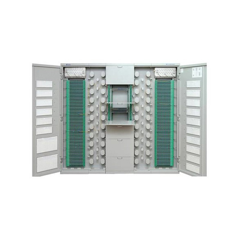
Product Overview
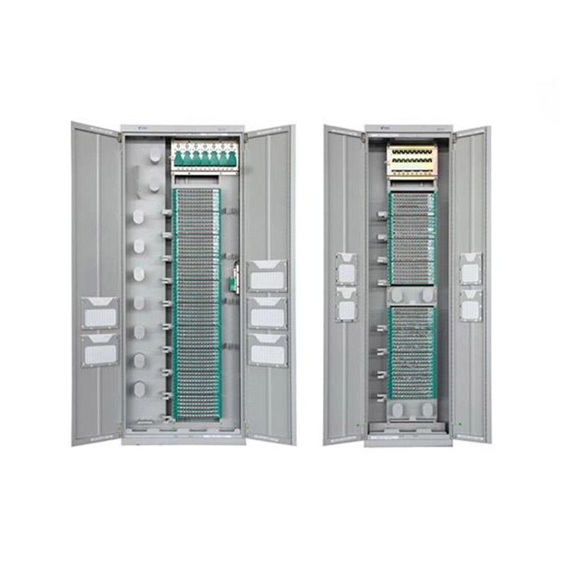
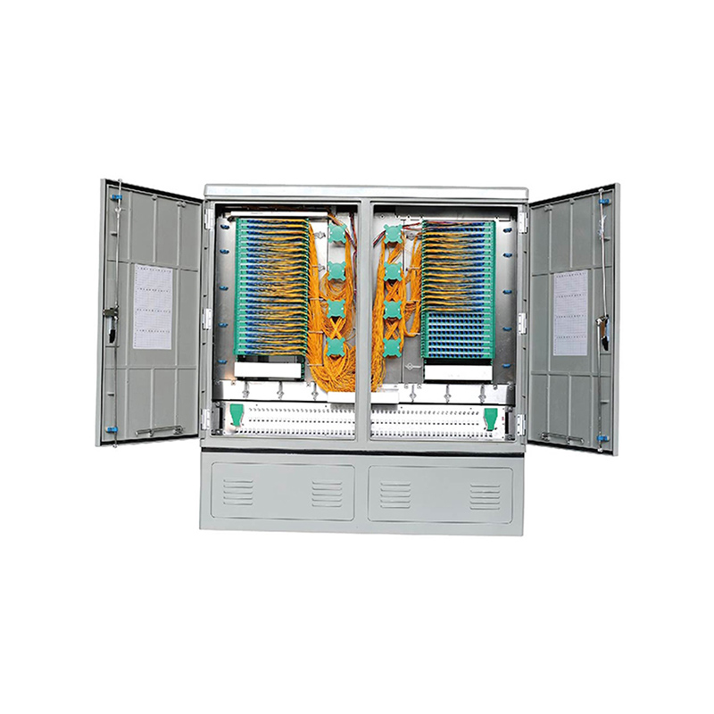
The Access Layer Optical Distribution Frame is an optical communication product developed for fiber access networks, especially FTTH environments that require centralized splitting and distribution. It integrates several key functional areas into one organized frame: an optical cable fixing area, a termination area, a patching area, and a splitting area. This integrated layout helps network teams manage large numbers of fibers while reducing the risks associated with messy cabling, excessive bending, unclear routing, and inefficient maintenance.
The frame uses a single-side operating structure and is available in Type A and Type B configurations. The frame system can include a basic frame, a fiber coiling frame, and an extended frame. This modular arrangement allows network planners to select a configuration according to project scale, cabinet room layout, fiber capacity, and service expansion needs. Instead of forcing every site to use one fixed structure, the system supports flexible deployment for different access-layer equipment room conditions.
One of the most important characteristics of the product is its use of a customized 12F integrated tray on the external line side. This tray improves versatility because it supports standardized handling of splicing and distribution. In addition, patch cords are routed with an “M”-shaped hanging structure, which helps maintain clean routing, improves visibility, and supports orderly patch cord management during daily operations.
In a high-density FTTH network, distribution frames often become the point where performance, maintenance efficiency, and network scalability either succeed or fail. A poorly designed frame may save space at first but later create operational difficulties, such as tangled jumpers, unclear fiber identification, limited splitter capacity, restricted access for technicians, and higher risk of accidental service interruption. This product addresses these challenges with a structural design that separates functions clearly while preserving high capacity within a compact footprint.
Typical Application Scenarios
The product is used in FTTH network access-layer equipment rooms where splitting, splicing, distribution, and other operations need to be performed within the same frame. This is especially suitable for central points in residential broadband networks, building access rooms, telecom operator access sites, industrial park communication rooms, and broadband expansion projects.
It is also suitable for FTTH networks where optical splitting needs to be performed at a fixed location. In many access networks, centralized splitting simplifies planning and improves management because splitters, feeder fibers, distribution fibers, and patch cords can be handled in one controlled physical environment. A fixed splitting location also helps operators implement standard maintenance procedures and reduce uncertainty during troubleshooting.
For rail transit communication facilities, urban infrastructure projects, and high-density Ethernet optical network deployments, a stable access-layer optical distribution frame can serve as a reliable passive infrastructure node. While active network equipment may change over time, the passive fiber management layer must remain stable, organized, and serviceable for many years. Therefore, the mechanical structure, tray design, routing system, and cabinet manufacturing quality are critical to total network reliability.
Core Structural Design
The frame adopts a single-side structure. Single-side operation is valuable in crowded access-layer rooms because it can reduce aisle requirements and simplify installation against walls or within aligned equipment rows. Compared with double-side systems that may require technician access from both front and rear sides, a single-side layout can be easier to deploy in limited spaces and may improve space utilization in access facilities.
The complete frame system may consist of a basic frame, a fiber coiling frame, and an extended frame. The basic frame is generally used for the splitting area. The extended frame is used for termination and, depending on the configuration, may also support additional splitting areas. The fiber storage and management frame is used for patch cord storage and routing organization. This combination enables a layered fiber management strategy rather than placing all functions in one crowded compartment.
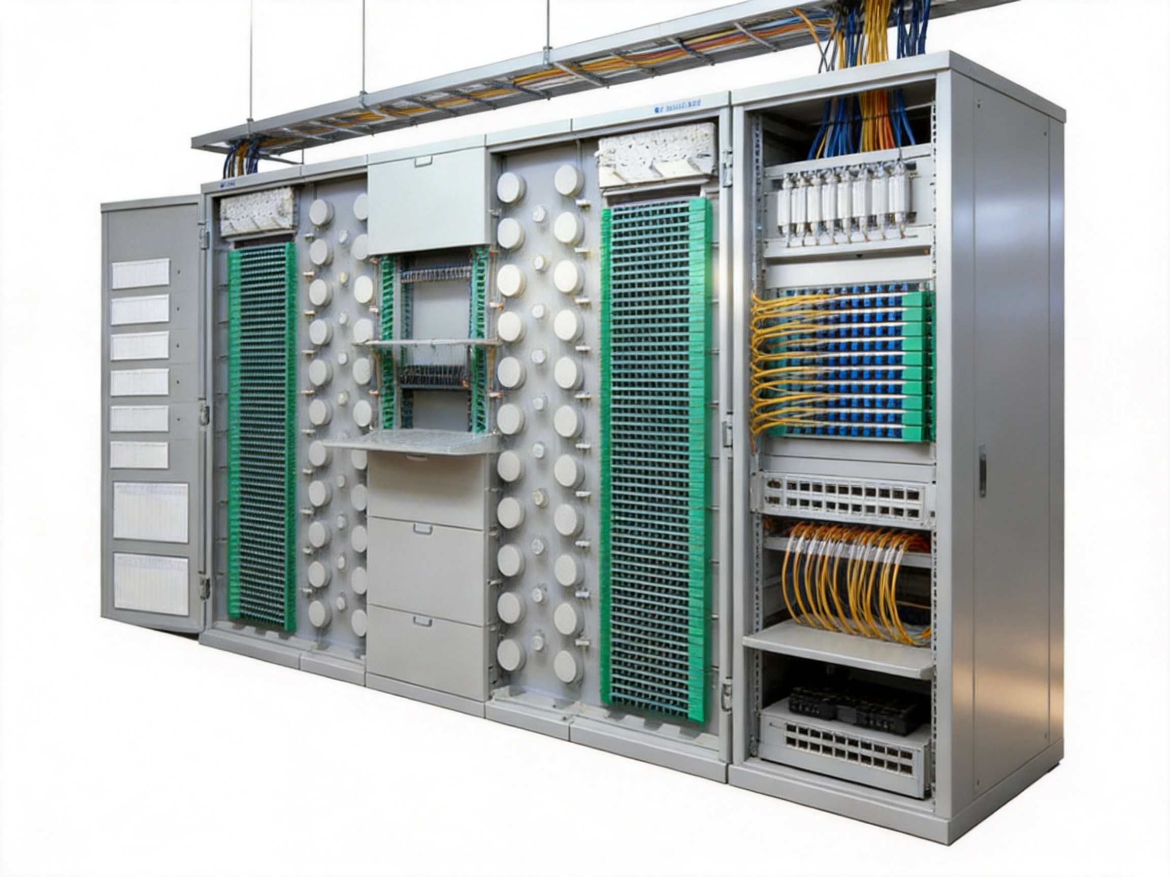
The frame integrates optical cable fixing, termination, patching, and splitting areas. This separation is a competitive advantage compared with ordinary cabinets or simple rack assemblies that may not provide dedicated spaces for each operation. In optical distribution, the physical separation of functions helps protect fibers from unnecessary movement, reduces bending stress, improves documentation clarity, and allows technicians to work on one section without disturbing another.
The external line side adopts a customized 12F integrated tray. The 12-fiber tray format is practical because many optical cable structures, splicing procedures, and distribution planning methods are based on fiber groups. By using integrated trays, the frame helps standardize fiber handling, reduce installation variation, and improve maintenance repeatability.
The “M”-shaped patch cord hanging structure is another important design feature. Patch cords in a high-density frame must be routed in a way that prevents random crossing, sharp bending, hanging pressure, and visual confusion. The “M”-shaped structure provides an organized path that supports natural routing and fiber storage. This helps maintain a neat appearance and supports more efficient identification when technicians add, remove, or modify services.
Type A and Type B Configuration Logic
The product is available in Type A and Type B configurations. The purpose of offering two types is to support different network room layouts and different capacity planning strategies. A network project with moderate growth needs may choose a simpler configuration, while a project requiring more segmentation, additional termination zones, or more complex left and right fiber storage may select a more advanced arrangement.
Type A is suitable for sites that require a basic splitting area, an extended termination area, and a fiber storage and management frame. It is straightforward, efficient, and suitable for many access-layer equipment rooms where a clear distribution path is required.
Type B is designed for more complex arrangements. It includes a basic frame for a splitting area, left and right extended frames for termination and additional splitting functions, and left and right fiber storage and management frames for patch cord areas. This configuration is suitable for access sites where higher organization, segmented routing, or future expansion needs are important.
By offering these two configurations, the product avoids the limitation of one-size-fits-all infrastructure. Compared with competitors that may provide only a fixed cabinet model, this modular structure gives network planners more room to match the frame to the service model, building layout, and growth forecast.
Capacity and Ordering Reference
The following table summarizes representative ordering information for Type A and Type B frame configurations. Capacity values are based on the provided 1:32 splitting reference and listed frame dimensions.
Configuration |
Frame Section |
Dimensions H × W × D |
Capacity Reference |
Key Notes |
Type A |
Basic Frame, Splitting Area 1 |
2200 × 500 × 300 mm |
6 slots per unit, 12 units per frame, 1152 cores |
Tray type splitter; main splitter types include 1:32 and 1:64 |
Type A |
Basic Frame, Splitting Area 1 |
2000 × 500 × 300 mm |
6 slots per unit, 11 units per frame, 1056 cores |
Suitable for medium to high-capacity access rooms |
Type A |
Basic Frame, Splitting Area 1 |
1800 × 500 × 300 mm |
6 slots per unit, 10 units per frame, 960 cores |
Balanced height and capacity for standard deployments |
Type A |
Basic Frame, Splitting Area 1 |
1600 × 500 × 300 mm |
6 slots per unit, 8 units per frame, 768 cores |
Compact option for limited spaces |
Type A |
Extended Frame, Termination Area 1 |
1600 to 2200 × 500 × 300 mm |
72 cores per unit; frame unit count varies by height |
12F splice and distribution integrated tray; aluminum-shell splitter tray with cable outlets on both sides |
Type A |
Fiber Storage and Management Frame |
1600, 1800, 2000, or 2200 × 300 × 300 mm |
Fiber storage |
Supports patch cord management area |
Type B |
Basic Frame, Splitting Area 1 |
1600 to 2200 × 500 × 300 mm |
768 to 1152 cores according to frame height |
Splitter tray with aluminum shell and cable outlets on both left and right sides |
Type B |
Left and Right Extended Frames |
1600 to 2200 × 500 × 300 mm |
72 cores per unit; frame unit count varies by height |
Termination Area 1, Termination Area 2, and Splitting Area 2 functions |
Type B |
Left and Right Fiber Storage and Management Frames |
1600, 1800, 2000, or 2200 × 300 × 300 mm |
Fiber storage |
Supports Patch Cord Area 1 and Patch Cord Area 2 |
This table demonstrates that the frame is not limited to one height or one fixed capacity. Heights of 1600 mm, 1800 mm, 2000 mm, and 2200 mm make the system suitable for different rooms, ceiling conditions, installation practices, and capacity needs. The 500 mm width and 300 mm depth for the main frames help maintain a compact footprint, while the 300 mm width fiber storage frame gives additional routing capacity without overloading the main working zones.
Advantages in FTTH Access-Layer Construction
The first major advantage is high-density capacity. With configurations reaching up to 1152 cores in the basic frame under the listed 1:32 capacity reference, the product supports large-scale FTTH service aggregation. High density is essential for operators that need to serve many subscribers from a controlled access point while minimizing room footprint.
The second advantage is modular expandability. The frame can be built from a basic frame, extended frame, and fiber storage and management frame. This makes it easier to start with a practical configuration and expand as demand grows. In competitive systems with less modularity, operators may need to replace cabinets, add unrelated auxiliary racks, or accept less organized fiber routing. A modular access-layer distribution frame helps avoid these issues.
The third advantage is functional separation. Optical cable fixation, termination, patching, and splitting are not randomly mixed. Dedicated areas improve installation workflow and reduce the risk of accidental disruption. During maintenance, a technician can identify whether the task belongs to cable entry, splicing, splitter management, patch cord routing, or storage. This clarity reduces troubleshooting time.
The fourth advantage is better patch cord routing. The “M”-shaped hanging structure helps organize patch cords in a predictable path. In real access rooms, patch cord disorder can become a major source of service risk. When jumpers are tangled, a technician may accidentally pull or bend the wrong fiber. Organized routing reduces the possibility of human error.
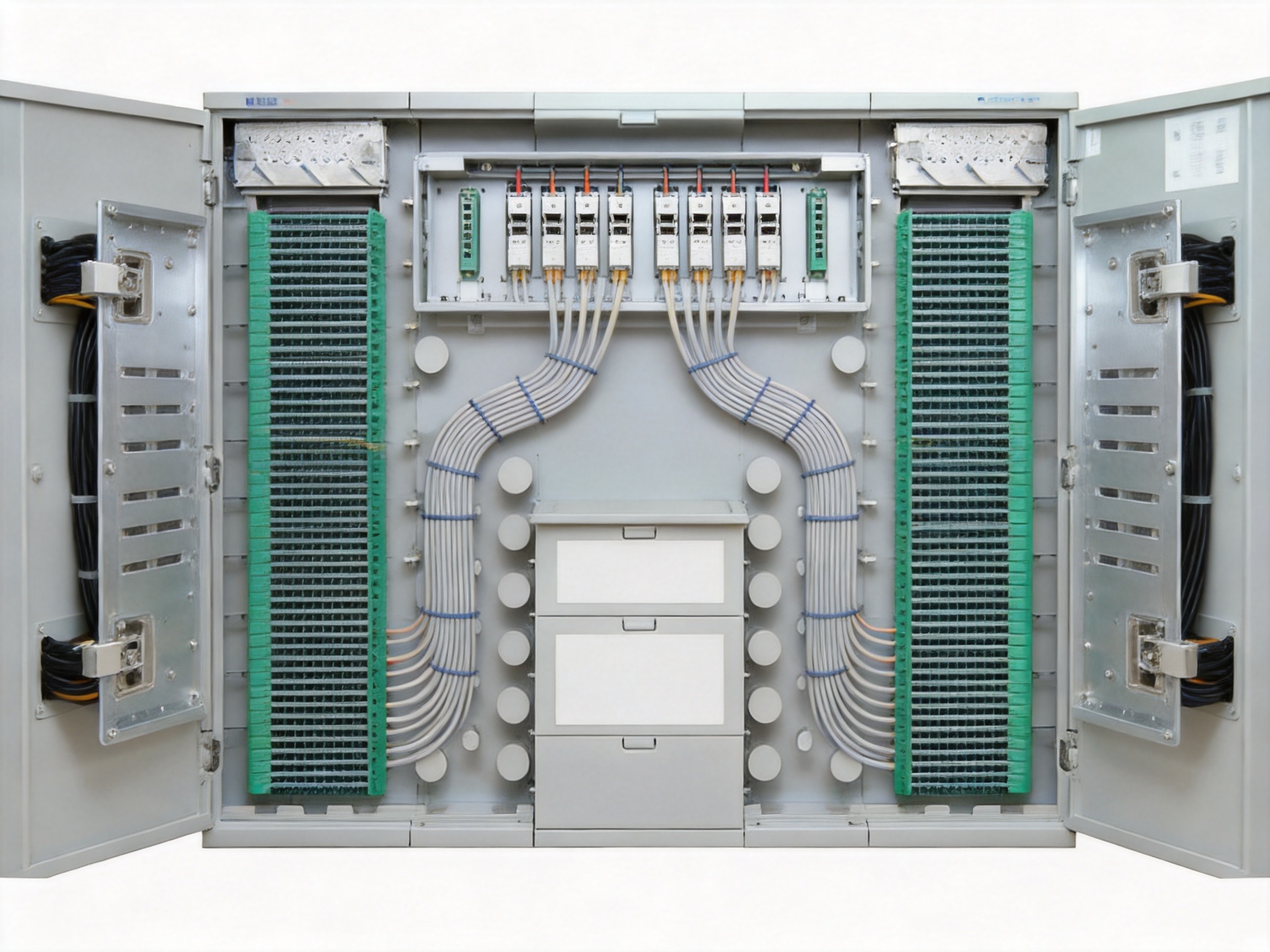
The fifth advantage is versatile tray design. The customized 12F integrated tray on the external line side improves standardization. A 12-fiber tray structure supports group-based splicing and distribution, making installation more systematic. The splitter tray with aluminum shell and outlets on both left and right sides also supports flexible cable routing and improves mechanical protection.
The sixth advantage is efficient use of room space. The single-side structure allows the frame to be used in constrained equipment rooms where rear access is inconvenient. By concentrating operations on one side, the system can simplify room planning and improve the practicality of dense deployment.
Advantages Over Conventional Competitor Solutions
Compared with basic optical distribution cabinets that only provide simple termination or patching, this access-layer frame integrates splitting, splicing, distribution, cable fixation, and fiber storage. This reduces the need for multiple separate cabinets and helps create a more unified network node. A unified frame is easier to plan, document, operate, and inspect.
Compared with conventional high-density racks that focus mainly on capacity, this product balances capacity with fiber management. Some competing solutions can appear attractive because they offer many ports, but they may lack sufficient patch cord routing space or clear separation between functional zones. High density without proper routing can produce congestion. This frame addresses density and manageability together.
Compared with frames that use less flexible cable entry and tray routing, the aluminum-shell splitter tray with cable outlets on both the right and left sides provides better adaptability. Cable routing direction matters because each equipment room has different feeder cable entry positions, wall arrangements, and operator habits. Left and right outlets reduce routing restrictions and support cleaner installation.
Compared with products that depend heavily on site improvisation, this frame provides a more engineered structure. The integrated tray system, dedicated areas, and patch cord hanging method reduce the need for technicians to create temporary routing paths during installation. This improves consistency from one site to another.
Compared with low-cost generic frames, the product is backed by a manufacturer with long-term experience in communication cabinets, communication electronic equipment, and passive optical components. Manufacturing knowledge matters because an optical distribution frame must combine mechanical strength, dimensional accuracy, surface treatment quality, fiber protection, tray usability, and assembly consistency. A frame is not merely a metal enclosure; it is a precision infrastructure product for passive optical networks.
Compared with solutions that support only one deployment style, Type A and Type B configurations provide broader network design flexibility. Some access sites need a compact and direct layout, while others require left and right routing zones, multiple termination areas, or additional splitting capacity. Providing different configurations helps reduce project compromise.
Compared with frames that may become difficult to maintain after several expansion cycles, this product’s fiber storage and management frame supports patch cord organization over time. Good initial installation is important, but long-term maintenance is equally important. A frame must remain serviceable after many additions, removals, upgrades, and subscriber changes. Structured storage supports long-term network cleanliness.
Manufacturing Strength and Industrial Experience
The product is manufactured by Wanma Technology Co., Ltd., a company established in 1997 with specialization in communication cabinets, communication electronic equipment, and passive optical components. This background is important because access-layer optical distribution frames require the intersection of sheet metal cabinet manufacturing, passive optical engineering, cable management design, and network deployment knowledge.
Since its establishment, the company has developed, manufactured, and marketed its own branded products while also providing integrated solutions for customized projects. This combination of standard product capability and customization experience is valuable for access-layer deployments because no two network rooms are exactly the same. Some customers need standard FTTH access frames, while others require adjusted dimensions, special routing, integration with existing facilities, or project-specific arrangements.
The company’s products are widely used in Ethernet networks, optical communication networks, central equipment rooms, national high-speed railways, and urban rail transit systems. These application environments require stable quality and dependable delivery because communication infrastructure must operate continuously. Railway and urban transit applications, in particular, place high expectations on mechanical reliability, organized installation, and long-term serviceability.
Advanced manufacturing processes contribute directly to product reliability. In communication cabinet production, key processes may include precision material selection, numerical control cutting, bending, welding, surface treatment, assembly inspection, tray fitting, dimensional verification, and packaging control. Accurate sheet metal processing ensures that trays slide smoothly, doors and panels align correctly, frames remain stable, and installed components are properly positioned.
Surface treatment is also important. Optical distribution frames are often installed in equipment rooms where long service life is expected. Proper surface finishing supports corrosion resistance, clean appearance, and durability. A well-treated cabinet surface also reflects disciplined manufacturing control, which is important for infrastructure products that may remain in service for many years.
Assembly quality determines whether the product is easy to install and maintain. If frame holes, tray guides, cable routing components, and mounting locations are inconsistent, technicians lose time during installation and maintenance. Manufacturing consistency improves field efficiency. A stable production process helps ensure that each frame matches the design intent and supports repeatable installation results.
The company’s experience in passive optical components supports the product’s tray and splitter integration. Passive optical network products must protect optical fibers from stress, maintain bending radius, and support reliable splicing and distribution. Knowledge of passive components helps the manufacturer design frames that are not only mechanically strong but also fiber-friendly.
In addition, the company emphasizes reliable product quality, timely delivery, and long-term strategic partnerships with industry leaders. These strengths matter in large network construction projects because delivery delays and quality inconsistencies can disrupt project schedules. A distribution frame supplier must be able to support procurement planning, production coordination, shipment, and after-sales communication.
Fiber Management and Network Reliability
Fiber management is one of the most important performance factors in an access-layer optical distribution frame. Optical fiber is sensitive to bending, pulling, compression, and poor routing. Even when optical components are technically correct, improper physical management can cause attenuation, intermittent faults, or long troubleshooting times.
The frame’s integrated layout helps manage fiber movement from cable entry to service output. Optical cables are first fixed in a dedicated area, which reduces movement and protects splicing areas from mechanical stress. Fibers then move toward termination and distribution trays, where splicing and organization can be carried out in a controlled manner. Splitters are placed in the splitting area, and patch cords are routed through the designed patching and storage zones.
This orderly path reduces fiber crossing and minimizes unnecessary handling. In a less organized cabinet, feeder fibers, distribution fibers, pigtails, and patch cords may overlap in the same space, making it hard to identify the correct fiber. The product’s structure reduces this problem by assigning functions to dedicated areas.
The “M”-shaped hanging structure for patch cords is especially useful in high-density environments. It allows patch cords to follow a designed route instead of hanging randomly across the frame. This supports bend radius control and helps technicians visually track routing. When a service change is required, the technician can work with greater confidence.
Long-term reliability is not only about optical specifications; it is also about reducing operational risk. Many network outages occur during maintenance or expansion when the wrong fiber is moved or a congested routing path is disturbed. A well-designed optical distribution frame reduces these risks by making the physical network easier to understand.
Splitter Integration and Capacity Planning
Optical splitting is central to FTTH network design. The frame supports tray type splitters, with main splitter types including 1:32 and 1:64. These splitting ratios are commonly used in passive optical networks where one feeder fiber is divided into multiple distribution fibers for subscriber access.
Capacity planning depends on the network architecture, service area, subscriber density, and operator standards. A 1:32 splitting design may support stable planning for many FTTH deployments, while a 1:64 design may be selected where higher split ratios are acceptable according to optical budget and service requirements. The frame’s ability to accommodate these splitter types gives designers flexibility.
The basic frame capacities listed for different heights provide options for different network sizes. The 2200 mm frame supports 12 units and 1152 cores, while the 1600 mm frame supports 8 units and 768 cores. This allows operators to select a frame height according to subscriber demand and available room space.
The extended frame termination area provides 72 cores per unit, with total frame capacity varying according to unit count. This helps match termination capacity with splitting capacity. A network node must avoid imbalance; if splitter capacity is high but termination management is insufficient, the site may become difficult to use. The combination of basic and extended frames supports balanced design.
In Type B configuration, the additional termination and splitting arrangement offers more flexibility for large or segmented access networks. Left and right extended frames can support clearer routing and division of service areas. This can be useful when a room serves different buildings, neighborhoods, floors, or service zones.
Installation Efficiency
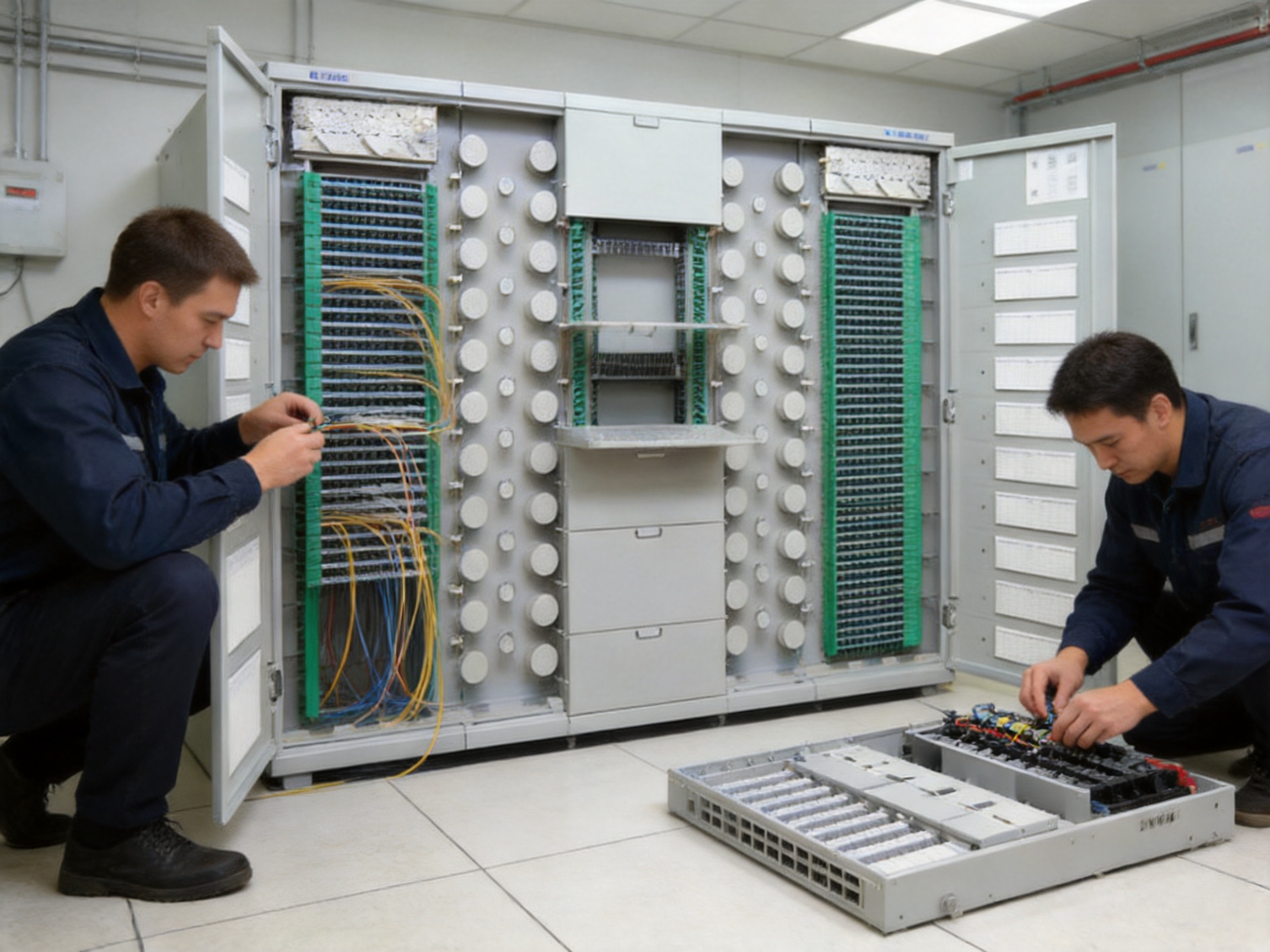
Installation efficiency is a major cost factor in access network construction. A well-designed distribution frame helps reduce labor time, field adjustments, and rework. Because this frame integrates multiple functions and provides dedicated structural zones, installers can follow a logical workflow.
The single-side operation structure reduces the need for rear access. In many access rooms, the back side of a cabinet may be close to a wall or another equipment row. If a frame requires rear access for installation or maintenance, room planning becomes more difficult. Single-side operation simplifies the physical layout and can reduce installation constraints.
The 12F integrated tray supports systematic splicing and distribution. Group-based tray handling helps technicians work in an organized way. Clear tray structure can reduce confusion during initial installation, service activation, and future expansion.
The fiber storage and management frame supports patch cord organization from the beginning of the project. Many cabinets look clean when first installed but become disordered after multiple service changes. Providing a dedicated storage area helps preserve neat routing as the network grows.
The modular frame system can also simplify logistics. Instead of using unrelated accessories from different sources, the basic frame, extended frame, and storage frame can be planned as a coordinated system. This helps reduce compatibility issues and supports more predictable field assembly.
Maintenance and Operational Benefits
Network operators must consider not only how a frame performs on installation day but also how it performs after years of subscriber growth, equipment upgrades, and maintenance tasks. The Access Layer Optical Distribution Frame is designed to support long-term operation by improving visibility, routing discipline, and separation of functions.
During troubleshooting, technicians need to identify fiber paths quickly. A frame with clear zones and organized patch cord routing reduces time spent searching for connections. Reduced troubleshooting time can lower operating costs and improve service restoration speed.
During expansion, technicians need available routing paths and storage capacity. The fiber coiling frame and fiber storage and management frame support this need. Without proper storage, excess patch cord length may be forced into random spaces, increasing bend risk and making future work harder.
During service changes, patch cords may need to be added, removed, or re-routed. The “M”-shaped hanging structure provides a stable routing habit, helping technicians avoid unnecessary disturbance to existing fibers. This is particularly important in high-density access rooms where many customers depend on the same passive infrastructure.
During inspection, a neat frame allows supervisors and quality teams to verify installation standards more easily. Visual order is not merely cosmetic; it indicates that fibers are likely routed according to plan and that future maintenance will be manageable.
Quality Control and Product Consistency
Quality control for an optical distribution frame should include material inspection, structural dimension checks, tray fit verification, surface treatment inspection, assembly quality review, and packaging protection. These controls are important because small mechanical inconsistencies can become major field problems.
Dimensional accuracy ensures that frames align properly during installation and that trays can be inserted and removed smoothly. A high-density frame may include many trays and routing components, so cumulative tolerances must be controlled. Precision manufacturing reduces field adjustment time and improves user experience.
Tray quality is especially important. Trays must support fiber routing without sharp edges, rough surfaces, or awkward handling. Integrated trays should protect fibers during splicing and distribution while allowing technicians to access fibers when needed.
Frame strength is also essential. A distribution frame may hold many components and cables. The structure must remain stable during installation, patching, and maintenance. Good cabinet manufacturing experience supports rigidity, alignment, and durability.
Packaging quality should not be overlooked. A well-manufactured frame must be protected during transport. Proper packaging reduces shipping damage and helps ensure that the product reaches the site ready for installation.
Customization and Integrated Solutions
Access-layer network projects often require customized planning. Room dimensions, cable entry directions, service growth forecasts, operator standards, and existing infrastructure conditions can vary widely. The manufacturer’s ability to provide integrated solutions for customized products is therefore an important advantage.
Customization may involve configuration selection, frame height planning, tray arrangement, cable routing strategy, patch cord storage design, and integration with existing optical communication systems. Instead of treating the frame as a standalone metal product, a solution-oriented manufacturer can help match the frame to the network design.
For customers deploying FTTH modernization projects, 5G transport support infrastructure, Ethernet optical networks, or rail transit communication systems, integrated planning can reduce risk. Passive infrastructure must be correctly designed from the beginning because later modifications can be expensive and disruptive.
The company’s global sales network, covering more than 20 countries and regions, also supports export project experience. Different markets may have different installation habits and project requirements. International experience helps a manufacturer understand diverse customer expectations and deliver more practical solutions.
Role in 5G and Broadband Modernization
Although the frame is a passive optical product, it plays an important role in modern broadband and 5G-related infrastructure. 5G networks, cloud services, high-definition video, smart homes, enterprise connectivity, and industrial digitalization all increase demand for reliable fiber access. The access-layer optical distribution frame provides the physical foundation for connecting feeder networks to distribution networks.
In broadband modernization projects, older distribution points may become overloaded or poorly organized. Upgrading to a high-density access-layer optical distribution frame can improve service capacity, simplify management, and prepare the network for future growth. A modern frame supports not only today’s subscriber demand but also future service evolution.
For Ethernet optical networks, stable passive distribution supports active equipment performance. Switches, optical line terminals, and transmission equipment depend on clean and reliable fiber connections. If the passive layer is disorganized, even advanced active equipment may experience avoidable operational problems.
For railway transit and urban communication systems, optical distribution frames contribute to reliable signaling, communication, monitoring, and passenger service networks. Infrastructure environments that require stable operation benefit from organized passive optical management.
Economic Value
The economic value of a high-quality access-layer optical distribution frame should be evaluated across the full life cycle, not only the purchase price. A low-cost frame that creates installation delays, cable disorder, limited expansion, or frequent maintenance difficulty may become expensive over time.
This product can reduce life-cycle cost by improving installation efficiency, reducing rework, supporting expansion, and lowering maintenance risk. High capacity helps reduce the number of frames required in some deployments. Modular configuration allows customers to select suitable capacity instead of overbuilding or underbuilding.
Reliable manufacturing quality also reduces hidden costs. Frames that arrive damaged, fail to assemble properly, or require field modification can delay project schedules. Consistent production and timely delivery support predictable construction progress.
Operational cost savings may also result from faster troubleshooting and safer service changes. In a large FTTH network, even small improvements in maintenance efficiency can become significant when multiplied across many sites and many years.
Selection Guidance
When selecting an Access Layer Optical Distribution Frame, project teams should first evaluate required fiber capacity. The number of subscribers, split ratio, feeder fibers, distribution fibers, and expected growth should be considered. A 2200 mm frame may be suitable for high-capacity nodes, while a 1600 mm option may be appropriate for smaller rooms or limited spaces.
Second, teams should choose between Type A and Type B. Type A is efficient for many standard access-layer applications. Type B is preferable where left and right routing, multiple termination zones, or additional splitting organization are required.
Third, teams should review room layout. Single-side operation is beneficial, but cable entry direction, wall position, aisle space, and adjacent equipment should still be evaluated. The frame should be placed where technicians can work safely and where cables can enter without excessive bending.
Fourth, teams should plan patch cord storage from the beginning. Patch cord management is often underestimated. Adequate storage and routing discipline help preserve long-term network quality.
Fifth, teams should consider future upgrades. FTTH networks usually grow over time. Selecting a modular frame system with expansion capability helps avoid costly replacement later.
Q&A Section
What is the main purpose of the Access Layer Optical Distribution Frame?
The main purpose is to provide a centralized frame for FTTH access-layer equipment rooms where optical cable fixing, splicing, termination, patching, splitting, distribution, and fiber storage must be managed in an organized way.
Where is this product typically used?
It is typically used in FTTH access-layer rooms, fixed optical splitting locations, broadband access sites, central equipment rooms, Ethernet optical network facilities, railway communication systems, and urban transit communication infrastructure.
What are the main differences between Type A and Type B?
Type A provides a practical configuration with a basic splitting frame, an extended termination frame, and a fiber storage and management frame. Type B provides a more expanded arrangement with left and right extended frames and left and right fiber storage management frames, supporting more complex termination, splitting, and patch cord management requirements.
Why is the single-side structure important?
The single-side structure helps save room space and simplifies operation in equipment rooms where rear access may be limited. It supports installation and maintenance from one side, which can improve practicality in dense access environments.
What capacity can the basic frame support?
Depending on height, the basic frame can support 768 cores, 960 cores, 1056 cores, or 1152 cores under the listed 1:32 capacity reference. The 2200 mm version supports up to 1152 cores.
What splitter types are supported?
The frame supports tray type splitters, with main splitter types including 1:32 and 1:64. Selection depends on optical budget, network design, service density, and operator standards.
Why is the customized 12F integrated tray useful?
The 12F integrated tray supports organized splicing and distribution in fiber groups. It improves versatility, makes installation more systematic, and supports easier maintenance.
How does the “M”-shaped hanging structure help?
The “M”-shaped hanging structure provides an orderly patch cord routing path. It helps reduce cable disorder, supports bend radius control, improves visual identification, and lowers the risk of accidental disturbance during maintenance.
What advantages does this frame offer over ordinary optical distribution cabinets?
It offers higher integration, better functional separation, stronger patch cord management, flexible Type A and Type B configurations, high-density capacity, and a tray-based structure designed for FTTH access-layer needs.
Why is manufacturing experience important for this product?
Manufacturing experience affects frame strength, dimensional accuracy, tray quality, surface treatment, assembly consistency, and long-term reliability. A distribution frame must protect optical fibers and remain serviceable for many years.
Conclusion
The Access Layer Optical Distribution Frame is a high-density, modular, and fiber-friendly solution for FTTH access-layer optical networks. It integrates cable fixing, termination, patching, splitting, and fiber storage into a structured frame system. With Type A and Type B configurations, multiple height options, 12F integrated trays, tray type splitter support, and “M”-shaped patch cord routing, it is designed to solve the real challenges of access-layer fiber management.
Its advantages over conventional competitor solutions are clear: better functional integration, stronger cable organization, higher configuration flexibility, efficient space usage, and long-term maintainability. For network operators and infrastructure builders, these advantages can translate into faster installation, easier troubleshooting, safer expansion, and more reliable service delivery.
Backed by a manufacturer with long experience in communication cabinets, passive optical components, Ethernet optical networks, central equipment rooms, railway transit communication systems, and customized integrated solutions, the product combines practical engineering with advanced manufacturing capability. In the modernization of FTTH, 5G supporting infrastructure, Ethernet optical networks, and urban communication systems, a dependable access-layer optical distribution frame is not optional; it is a foundation for stable network growth.
References
International Telecommunication Union. ITU-T G.984 Series: Gigabit-Capable Passive Optical Networks.
International Electrotechnical Commission. IEC 61753 Series: Fibre Optic Interconnecting Devices and Passive Components Performance Standards.
International Electrotechnical Commission. IEC 60794 Series: Optical Fibre Cables.
Telecommunications Industry Association. TIA-568: Generic Telecommunications Cabling for Customer Premises.
FTTH Council. FTTH Handbook: Planning, Design, and Deployment of Fiber Access Networks.
BICSI. Telecommunications Distribution Methods Manual.
International Organization for Standardization and International Electrotechnical Commission. ISO/IEC 11801: Information Technology, Generic Cabling for Customer Premises.
Product: Fiber Solution-Access Layer Optical Distribution Frame
PREV:20-Foot Containerized Data Center for Rapid, Reliable, and Scalable Digital Infrastructure
NEXT:High-Value Consumables House: A Digital Management Hub for Safer Medical Supply Control
NEXT:High-Value Consumables House: A Digital Management Hub for Safer Medical Supply Control
Interested in cooperation or have questions?
Related products
-
-
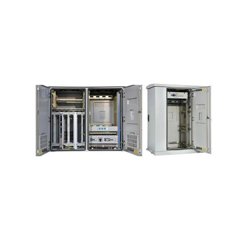
Application:It is used for the fixed network and broadband access, providing physical working environment and security system for the workstation in wired network. Features:•The cabinet is composed of...
See Details -
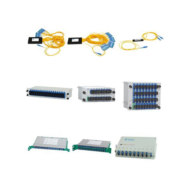
Application:It is used to split one optical signal to multiple output ports. The splitters can be divided into the micro type splitter, the box type splitter, the tray type splitter, and the frame typ...
See Details -
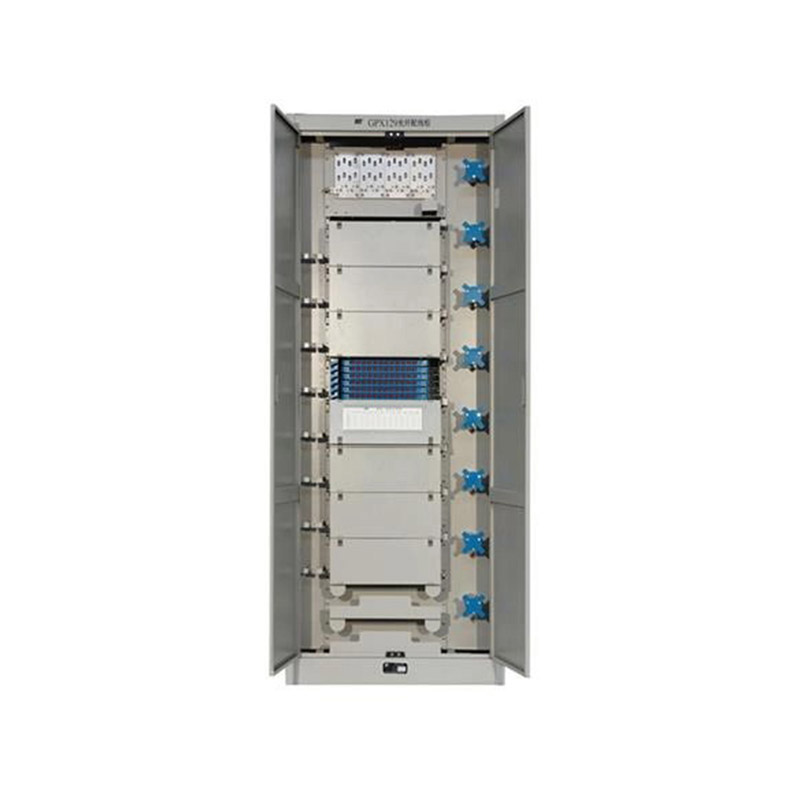
Application ScopeThe GPX129BKC fiber optic distribution frame is used to connect and distribute optical cables to optical communication equipment, and is suitable for large-capacity fiber optic commun...
See Details
Ready to Get started ? Contact Us Now !

Product.
Contact Details.
-
 +86 13958188250
-
 +86 13958188250
-
 [email protected]
- Wanma Industrial Park Taihu Yuan Town Lin'an District Hangzhou City China.
QR Code

Copyright © Wanma Technology Co., Ltd. All Rights Reserved.
Custom Ethernet Optical Network Railway Transit Equipments Suppliers
