

 English
 Français
 Español
 Português
 عربى






WM-1001-F055 It offers a wide range of functions which is needed in your Ftth broadband project in a compact and smart design. Extremely compact/variable transfer unit Multifunctional base plate Vario...
See DetailsCompact Fiber Optic Distribution Box for Flexible FTTH Network Deployment
Content
- 1 Product Overview and Design Purpose
- 2 Core Construction of the Distribution Unit
- 3 Splice and Connector Capacity
- 4 Protection and Environmental Suitability
- 5 Advantages Compared with Conventional Fiber Distribution Boxes
- 6 Manufacturing and Engineering Strengths
- 7 Recommended Installation Workflow
- 8 Use in Different Market Applications
- 9 Technical Specifications
- 10 Why Select This Product for a Network Project?
- 11 Procurement and Project Planning Considerations
- 12 Maintenance Recommendations
- 13 Questions and Answers
- 13.1 What is the primary purpose of the WM-1001-F055?
- 13.2 How compact is the distribution box?
- 13.3 Which connector types can it support?
- 13.4 Can the box accommodate a PLC splitter?
- 13.5 What microduct sizes are supported?
- 13.6 Does the product support different splice methods?
- 13.7 Is the enclosure suitable for outdoor use?
- 13.8 How does the lock improve network security?
- 13.9 What makes the product different from a basic fiber termination box?
- 13.10 Who manufactures the product?
- 13.11 Can the product be used in railway or utility communications?
- 13.12 What should be confirmed before placing an order?
- 14 Conclusion
- 15 References
- 16 Product: WM-1001-F055 Fiber Optic Distribution Box
Modern broadband networks depend on compact, reliable, and serviceable passive optical infrastructure. As fiber-to-the-home, fiber-to-the-building, enterprise access, utility communications, and broadband cable networks continue to expand, network operators need distribution equipment that can organize fibers, protect splices, accommodate different connector systems, and simplify installation in limited spaces. The WM-1001-F055 Fiber Optic Distribution Box is designed to address these requirements through a compact three-part housing, a multifunctional base plate, flexible cable entry arrangements, integrated splitter support, and a versatile splice cassette.
The product is developed for FTTH broadband projects in which space efficiency, installation flexibility, and long-term maintenance are essential. Rather than functioning only as a basic enclosure, the distribution box combines cable management, splitter positioning, splice protection, adapter accommodation, and access control in one wall-mounted unit. Its structure enables technicians to work on the base plate before the enclosure is fully assembled, helping make installation more organized and efficient.
Wanma Technology Co., Ltd. manufactures and supplies the WM-1001-F055 as part of its broader portfolio of communication cabinets, communication electronic equipment, and passive optical components. Established in 1997, the company serves Ethernet networks, optical communication networks, central equipment rooms, high-speed railway systems, and urban rail transit applications. This experience gives the product a practical design foundation that extends beyond a single residential broadband application.
The distribution box is particularly suitable for network environments where different fiber routes, splice methods, splitter configurations, and connector types may be required. Its ability to support LC duplex, SC simplex, and E-2000® couplers provides a degree of adaptability that can reduce the need for several enclosure models across a deployment program. With an IP54 environmental rating, the unit is also intended to provide protection against dust, dirt, and sand in appropriate indoor or sheltered outdoor installations.
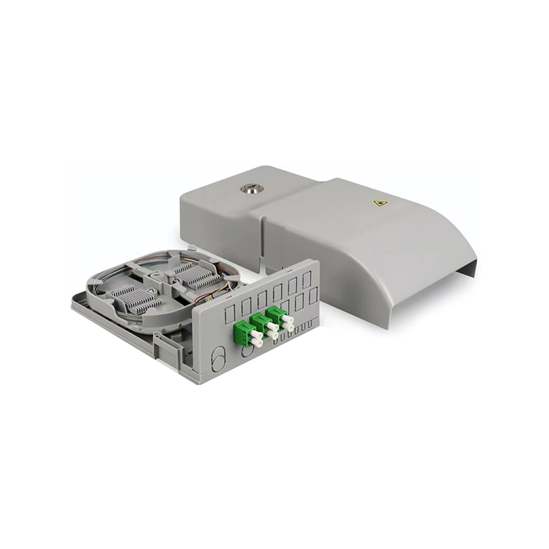
WM-1001-F055 Fiber Optic Distribution Box
Product Overview and Design Purpose
The WM-1001-F055 Fiber Optic Distribution Box is a compact fiber distribution and termination enclosure for FTTH and other optical access networks. It provides a controlled location for cable entry, fiber routing, splicing, splitter installation, adapter termination, and subscriber-side distribution. The unit measures 122 by 59 by 256 millimeters and weighs approximately 335 grams, making it suitable for installations where wall space, cabinet depth, and handling efficiency are important considerations.
A compact enclosure must balance several competing requirements. It must be small enough for installation in constrained locations, yet large enough to provide adequate fiber bend management and working room. It must allow technicians to access splices and connectors without unnecessarily disturbing adjacent fibers. It must also provide sufficient structural protection against dust and accidental contact. The WM-1001-F055 approaches this balance through a three-part housing consisting of a base plate, a splice cassette section, and a protective cover.
The base plate is installed at the selected location before the remainder of the distribution unit is assembled. This arrangement allows the technician to establish the mounting position, prepare cable routes, and organize the incoming fiber without being restricted by the final enclosure cover. Once the internal work is complete, the additional housing sections and long protective lid can be fitted into place.
The design is intended to support a broad range of FTTH broadband project requirements. It can be used where a passive optical network requires a compact termination point, where a PLC splitter must be mounted close to the distribution fibers, or where splicing and subscriber-side connectorization must be combined in one enclosure. The unit can also serve as a practical transition point between feeder, distribution, and drop cables.
Core Construction of the Distribution Unit
Three-Part Housing
The three-part housing is one of the product’s main practical advantages. In conventional compact fiber boxes, the installer may need to remove the entire enclosure or work through a narrow opening while positioning cables and splice components. A sectional housing can make the work sequence more logical by separating mounting, internal arrangement, and final protection.
The base plate provides the initial mechanical foundation. It can be fixed to the wall or another suitable mounting surface at the required location. Since the working area remains accessible during the early installation stages, the technician can prepare cable entries and identify component positions before closing the housing.
The second attachment contains the versatile splice cassette. This part provides dedicated space for fiber splicing and connector accommodation. The final long lid protects the assembled unit and helps prevent unauthorized or accidental access by subscribers. The lid can also be secured through the built-in cylinder lock, providing an additional level of physical control for network operators and service personnel.
This staged construction can be beneficial during both initial installation and later service work. Technicians can isolate the area requiring attention, inspect the splice cassette, and work with less interference from the external cable route. A clear separation between structural support, splice management, and protection also helps improve the consistency of field installation.
Multifunctional Base Plate
The base plate is designed to perform more than a simple mounting function. It incorporates a PLC splitter holder, cable entry options, space for a splice receptacle, and an area that can be used for through splicing. This multifunctional approach helps consolidate several passive optical tasks within a single compact product.
The integrated PLC splitter holder is important in FTTH networks that use centralized or distributed optical splitting. A splitter placed within the enclosure can divide an incoming optical signal for several subscribers or downstream distribution branches. By providing a designated position for the splitter, the product helps keep the component stable and reduces the chance of loose modules interfering with fiber routing.
The base plate also provides receptacle space for a splice receptacle. The supplied arrangement can be replaced by another suitable splice or shrink receptacle when a project uses a different splice protection method. This replaceable approach is valuable because installation contractors and network operators may use different splicing systems according to regional standards, existing inventory, or maintenance policy.
The lower plate area and crimp holder can be used for a through splice. This gives the installer another option for managing a continuous or passing fiber route without requiring a separate external splice enclosure. The choice between a standard splice fixture, shrink fixture, or crimp-based arrangement can be made according to the project’s fiber preparation and repair practices.
Flexible Cable Entry Arrangements
Fiber projects rarely follow a single cable routing pattern. Cables may enter from the top, bottom, side, or through a microduct arrangement. A distribution box with only one entry direction can create unnecessary bends, extra slack, or awkward wall routing. The WM-1001-F055 addresses this issue with various cable entry options integrated into the base plate.
Two cut-outs on the base plate support the insertion of 7-millimeter or 12-millimeter microducts. This feature allows the unit to be connected to different microduct configurations without requiring extensive field modification. Microduct compatibility can be particularly useful in dense urban deployments, buildings with pre-installed pathways, and projects that use blown fiber or protected small-diameter cable systems.
The intelligent cable guide helps the installer lay and fix cables in an orderly manner. Proper routing is important because optical fibers can be affected by excessive bending, crushing, pulling, or unintentional pressure from other components. A guided internal path supports better separation between incoming cables, splice areas, and connector positions.
Flexible entry design also improves the product’s suitability for retrofit work. Existing buildings and communication rooms may not provide a clean, standardized cable route. The ability to select a suitable entry point can simplify installation around walls, ducts, conduits, and previously installed network equipment.
Splice and Connector Capacity
Versatile Splice Cassette
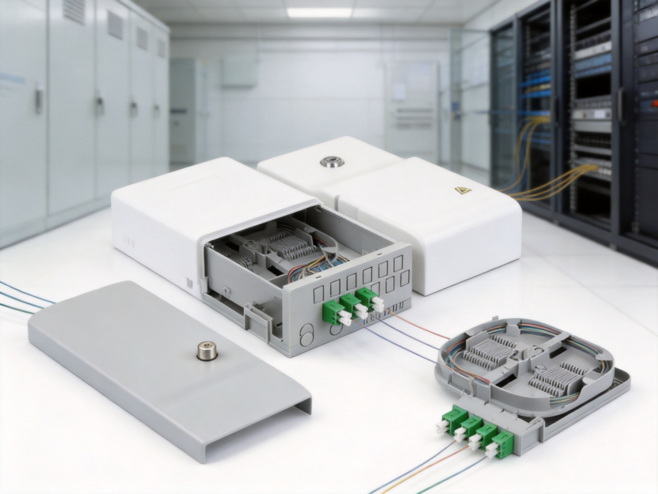
The splice cassette can accommodate up to 12 couplings and provides space for up to 24 fibers. This capacity makes the box suitable for compact distribution points that require more than a basic single-fiber termination but do not justify a large cabinet or rack-mounted fiber frame.
The cassette includes twelve knockouts that can be configured with up to 12 LC duplex couplers, 12 SC simplex couplers, or 12 E-2000® couplers. This configuration flexibility allows the same general enclosure platform to support different connector ecosystems. Operators can select a connector format according to the network design, installed customer equipment, maintenance tools, and regional preference.
LC duplex connectors are often selected where high port density is required. Their compact form can help maximize the number of optical interfaces within a limited panel area. SC simplex connectors are widely recognized for their straightforward handling and established use in access networks. E-2000® couplers may be selected for applications that require their particular connector design and operational characteristics.
Supporting several adapter options is a competitive advantage over single-format distribution boxes. A single-format enclosure can force an operator to purchase, store, and manage multiple product versions for different projects. A configurable platform can simplify procurement and make replacement planning more efficient, provided that the selected adapters and internal components are correctly specified for the intended network.
Crimp Splice Holders
The two receptacles in the splice cassette are occupied by two crimp splice holders for twelve fibers each. These holders can also be replaced with standard splice or shrink fixtures. This arrangement supports a practical balance between supplied functionality and field adaptability.
Crimp splicing can be useful when technicians require a secure mechanical fiber splice method without using a heat-shrink sleeve for every connection. In other projects, standard fusion splice protection or shrink fixtures may be preferred. By allowing the holders to be replaced, the enclosure can be adjusted to the operator’s selected fiber preparation method instead of locking the user into a single approach.
Splice protection is central to long-term network reliability. A properly protected splice is less vulnerable to mechanical disturbance, contamination, and accidental contact during maintenance. The enclosure’s dedicated cassette area helps keep splice points separate from general cable movement and connector handling.
The stated splice capacity in the product information is one splice, while the detailed design description identifies internal provisions for multiple fibers, crimp holders, and splice cassette positions. For a specific project, the final usable capacity should therefore be confirmed with the manufacturer according to the selected splice fixtures, splitter arrangement, connector configuration, and cable construction. This is a normal engineering step when adapting a modular fiber enclosure to a particular network design.
Protection and Environmental Suitability
The WM-1001-F055 carries an IP54 environmental rating. IP54 indicates protection against limited dust ingress and protection against water splashes from various directions. The product information further identifies resistance to dust, dirt, and sand. The rating makes the unit appropriate for many indoor, sheltered outdoor, telecommunications room, building entrance, utility, and controlled infrastructure locations.
IP54 protection should be considered within the context of the installation environment. The enclosure should be mounted according to the manufacturer’s instructions, with compatible cable entries and correctly secured covers. It is not intended to be treated as a fully waterproof underground closure or as a substitute for a higher-rated outdoor enclosure in locations exposed to driving rain, flooding, immersion, or severe chemical contamination.
The long cover provides a physical barrier over the internal components and helps prevent casual access by subscribers. The built-in cylinder lock adds a further access-control feature. This is valuable in shared buildings, public corridors, utility sites, and other locations where network equipment may be physically reachable by people who are not responsible for fiber maintenance.
The specified ambient temperature range is from minus 25 degrees Celsius to 70 degrees Celsius. This broad operating range supports many telecommunications and infrastructure environments. Temperature performance can depend on installation conditions, component selection, solar exposure, cable materials, and the overall enclosure location, so project designers should evaluate the complete environmental profile rather than relying on the enclosure rating alone.
Advantages Compared with Conventional Fiber Distribution Boxes
Efficient Use of Limited Space
One of the clearest advantages of the WM-1001-F055 is its compact form. With dimensions of 122 by 59 by 256 millimeters, it can be considered where a larger wall cabinet would be excessive or where several pieces of passive equipment must fit within a narrow service area. Compact equipment can reduce visual impact in building interiors and help preserve room for electrical, security, or building management systems.
However, compactness alone does not determine the usefulness of a fiber box. A small enclosure can become difficult to install if it lacks internal organization. The product combines its small dimensions with a cable guide, splitter holder, splice areas, adapter positions, and a sectional housing. This combination gives the compact enclosure practical working value instead of merely reducing its external size.
More Installation Options
Many basic fiber termination boxes provide a fixed cable entry and a fixed connector arrangement. The WM-1001-F055 is more adaptable through its various cable entry options, 7-millimeter and 12-millimeter microduct cut-outs, replaceable splice receptacle, and selectable coupler formats. These features can reduce the amount of field improvisation required when network layouts differ from the original design assumption.
Installation flexibility can also reduce the total number of enclosure models required by a network operator. If one product platform can support multiple connector and splice configurations, purchasing teams may be able to simplify inventory. Service teams can become familiar with one basic housing design while using different internal components for individual project requirements.
Improved Serviceability
Maintenance is a major lifecycle consideration for access networks. Fiber distribution points may need to be opened for fault isolation, subscriber activation, connector cleaning, splitter replacement, cable rearrangement, or future capacity expansion. A protected but accessible internal layout can reduce the risk of disturbing unrelated fibers during these tasks.
The three-part housing provides a logical working sequence, while the splice cassette and cable guide help separate different functions. The lockable long lid helps control access after maintenance is complete. Compared with a simple unstructured box, these characteristics can support more repeatable service procedures.
Support for Different Network Architectures
The enclosure can be used in several FTTH arrangements. It may serve as a small building distribution point, a floor-level termination unit, a compact fiber splitter box, or an intermediate point between feeder and drop cables. The PLC splitter holder supports optical splitting, while the splice and connector provisions support direct termination or spliced distribution.
Its use is not limited to residential broadband. The same functional requirements appear in small enterprise networks, utility communications, broadband cable infrastructure, transportation facilities, and certain wireless backhaul or fronthaul support environments. The company’s experience across Ethernet, optical communication, railway, and urban rail transit applications provides a relevant background for these broader deployments.
Manufacturing and Engineering Strengths
Experience in Passive Optical Components
Wanma Technology Co., Ltd. was established in 1997 and specializes in communication cabinets, communication electronic equipment, and passive optical components. This product background is significant because a fiber distribution box must be designed as part of a complete optical network rather than as an isolated plastic or metal enclosure.
Passive optical products must address mechanical protection, fiber routing, connector alignment, installation repeatability, and long-term access. Experience across these areas helps a manufacturer understand how an enclosure will be handled by installers, connected to other network components, and maintained over many years. The WM-1001-F055 reflects this application-oriented approach through its combination of cable organization, splice support, splitter mounting, and adapter flexibility.
Integrated Product Development
The company develops, manufactures, and markets products under its own brand while also providing integrated solutions for customized products. This capability can be valuable for customers whose requirements do not fit a standard catalog configuration. Potential customization discussions may involve connector type, internal splice fixtures, cable entry arrangements, branding, packaging, or integration with a wider communication cabinet system, subject to technical confirmation.
Integrated development also supports more consistent communication between product engineering, manufacturing, quality control, and customer service teams. When the supplier understands both the product design and the application environment, it can be easier to identify practical solutions to installation constraints.
Manufacturing Process Considerations
The manufacturing of a fiber distribution box requires control over multiple stages. Material selection must provide adequate mechanical strength, dimensional stability, and resistance to the expected environmental conditions. Housing components must be formed or molded with consistent dimensions so that the base plate, cassette, adapters, and cover align correctly.
Assembly quality is equally important. Cable guides, splitter holders, splice fixtures, locks, and cover fasteners must be installed securely and checked for correct operation. Misalignment in a connector panel or excessive pressure near a fiber route can create field problems even if the external enclosure appears satisfactory. A disciplined assembly process helps prevent such issues.
Quality control should also include visual inspection, dimensional checks, component verification, cover and lock operation, and confirmation that the specified internal accessories are included. Where applicable, manufacturers may perform environmental, mechanical, or ingress-related evaluations according to the product’s intended rating and applicable customer requirements.
For the WM-1001-F055, the practical manufacturing objective is to produce a compact housing that remains easy to assemble, compatible with the stated fiber accessories, and reliable under the specified temperature and environmental conditions. Consistency from one unit to the next is essential because installers need predictable mounting points, cable entries, and internal clearances.
Application-Based Engineering
Wanma Technology serves more than 20 countries and regions, including the United States, Australia, the United Kingdom, Italy, South Africa, and Ghana. International experience exposes a manufacturer to different building practices, cable types, connector preferences, installation regulations, and climate conditions. Such exposure can support more practical product development and a better understanding of regional network requirements.
The company’s products are used in Ethernet networks, optical communication networks, central equipment rooms, national high-speed railways, and urban rail transit systems. These sectors often require dependable passive infrastructure because access to installed equipment may be difficult, service interruptions may be costly, and cable management must remain orderly in equipment-dense environments.
The same engineering principles benefit FTTH applications. A distribution box must protect fiber pathways, simplify service access, control unauthorized handling, and remain compatible with the project’s optical architecture. The WM-1001-F055 applies these principles in a compact format intended for practical field deployment.
Recommended Installation Workflow
A successful installation begins with a site survey. The technician should identify the wall material, available clearance, cable approach direction, temperature conditions, expected dust or moisture exposure, and location of nearby network equipment. The selected position should provide sufficient room to open the lid and perform future maintenance.
The base plate should then be positioned and securely attached using mounting hardware appropriate for the wall or support structure. The installer should confirm that the mounting surface is stable and that the box will not be subjected to excessive vibration, impact, or cable tension.
Incoming and outgoing cables should be routed through the most suitable entry options. If microducts are used, the 7-millimeter or 12-millimeter cut-out should be selected according to the actual duct size and project design. Cable slack should be managed carefully so that fibers are not sharply bent or compressed against the housing.
The intelligent cable guide should be used to establish an orderly path. The cable should be fixed without excessive force, and the minimum bend radius specified for the particular fiber cable should be maintained. Different cable types may have different bend limits, so the cable manufacturer’s requirements should be followed.
If a PLC splitter is part of the network architecture, it should be installed in the designated splitter holder. The installer should verify the splitter’s input and output fiber routing before connecting it to the splice or adapter areas. Optical labels should be applied clearly so that future technicians can identify feeder, distribution, splitter, and subscriber-side fibers.
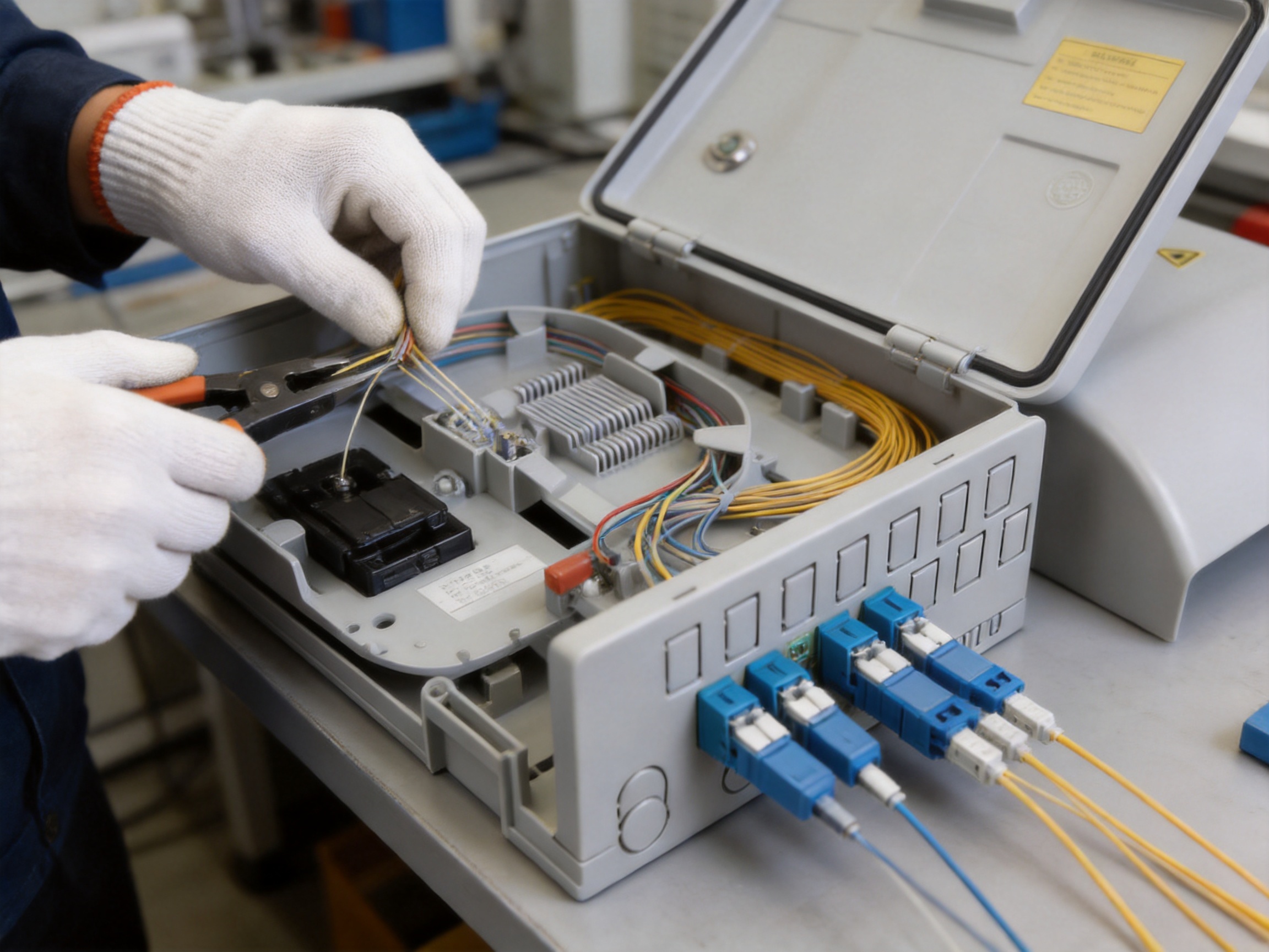
The selected splice receptacle or fixture should be installed in the appropriate base plate or cassette position. Fusion splices, crimp splices, or shrink-protected splices should be prepared according to the applicable technical procedure. Splice protectors must be seated correctly, and fiber loops should remain organized within the cassette.
Connector adapters can then be installed in the available knockouts. Up to 12 LC duplex, 12 SC simplex, or 12 E-2000® couplers may be accommodated according to the selected configuration. The installer should avoid mixing adapter types without confirming that the cassette and panel arrangement support the intended combination.
Before the housing is closed, the technician should inspect fiber routing, verify that no fiber is trapped beneath a component, confirm that the cover can be fitted without pressure on the cables, and check that all splice and connector positions are secure. The long lid should be closed and locked where access control is required.
Final commissioning may include visual inspection, optical power measurement, insertion-loss testing, continuity testing, connector end-face inspection, and documentation of the installed fibers. Accurate records make future repairs and subscriber activation more efficient.
Use in Different Market Applications
Residential FTTH
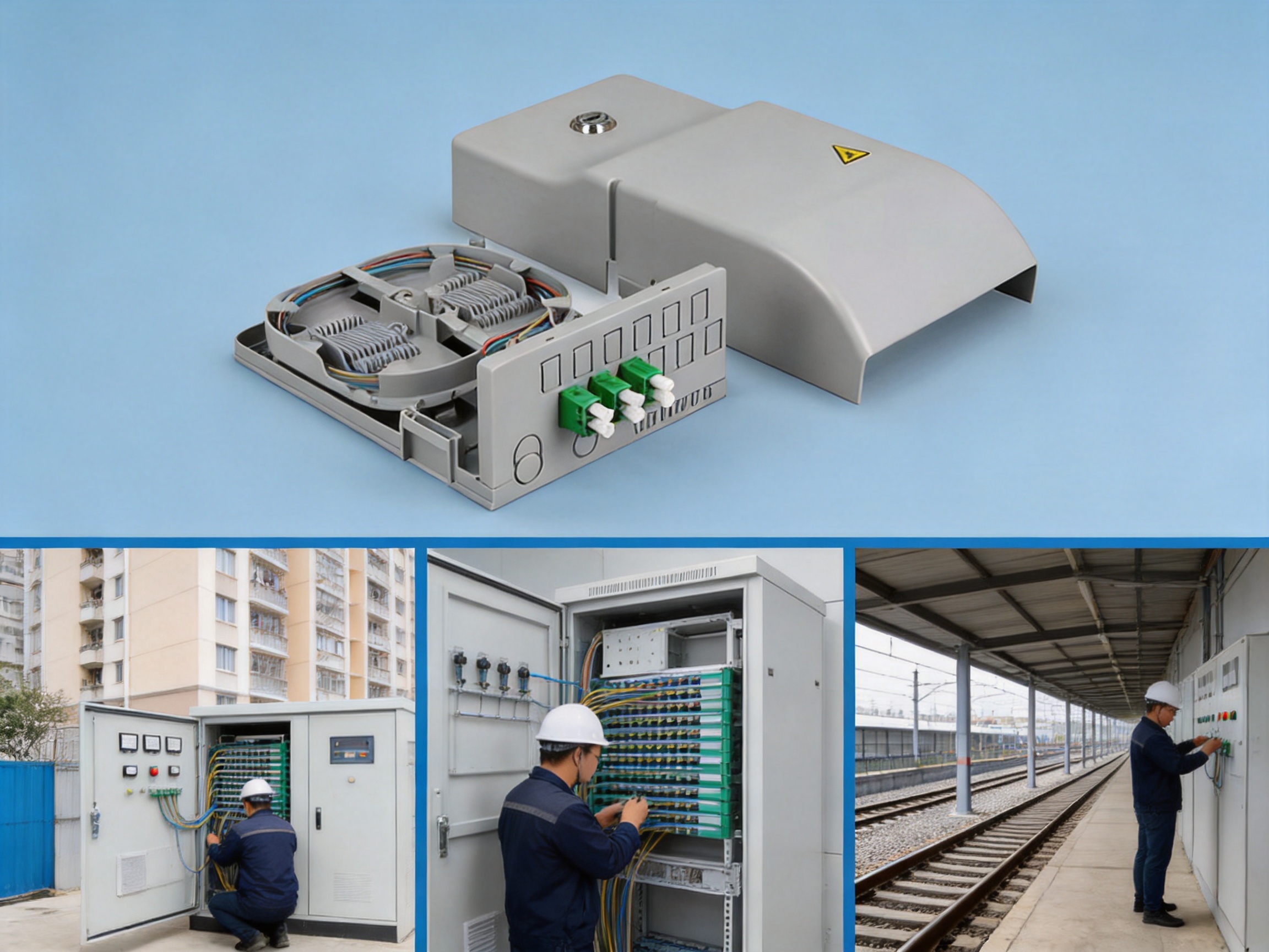
In residential FTTH deployments, the WM-1001-F055 can provide a compact point for fiber splitting, splicing, and subscriber distribution. Its lockable cover is useful in shared corridors, apartment buildings, and other areas where residents may be able to reach the equipment. The configurable connector area enables operators to match the box with the connector system already used in the access network.
Multi-Dwelling Buildings
Multi-dwelling buildings often require fiber infrastructure that fits within restricted risers, service closets, or floor-level communication spaces. The compact dimensions and multiple cable entry choices can assist with installation where a large cabinet is not practical. The enclosure can also support staged expansion if the internal layout is planned carefully and spare capacity is reserved.
Utility Networks
Utility communications networks may use fiber for monitoring, control, protection, and operational data. In these applications, a compact enclosure can provide a structured termination point near field equipment or a local communication room. The IP54 rating and broad temperature range may be suitable for selected utility environments, provided that the complete installation meets the site’s environmental requirements.
Broadband Cable Networks
Broadband cable operators increasingly use fiber deeper into the access network. A fiber distribution box can support the transition between optical feeder infrastructure and local distribution routes. The WM-1001-F055’s splitter and splice provisions can be adapted to network architectures that require compact optical branching and connector termination.
Transportation Infrastructure
Railway and urban rail transit systems require organized communications infrastructure across stations, control areas, equipment rooms, and trackside facilities. Wanma Technology’s involvement in high-speed railway and urban rail transit applications provides relevant industry experience. The WM-1001-F055 may be considered for suitable indoor or sheltered fiber distribution points where its environmental rating, capacity, and mounting arrangement meet the project specification.
Technical Specifications
| Parameter | Specification |
|---|---|
| Product | WM-1001-F055 Fiber Optic Distribution Box |
| Primary application | FTTH broadband and optical communication networks |
| Dimensions | 122 × 59 × 256 millimeters |
| Weight | Approximately 335 grams |
| Ambient temperature | Minus 25°C to 70°C |
| Environmental rating | IP54 |
| Environmental protection | Resistance to dust, dirt, and sand under the stated rating |
| Splice cassette capacity | Up to 12 couplings and space for up to 24 fibers, subject to configuration |
| Connector options | Up to 12 LC duplex, 12 SC simplex, or 12 E-2000® couplers |
| Microduct entry options | 7-millimeter and 12-millimeter cut-outs |
| Splitter support | Integrated PLC splitter holder |
| Housing structure | Three-part housing with base plate, splice cassette section, and protective lid |
| Access control | Built-in cylinder lock and side sealing provision |
Why Select This Product for a Network Project?
The most important reason to select the WM-1001-F055 is the combination of compactness and functional density. The product does not merely reduce enclosure size; it integrates several functions that are normally distributed across separate components. This can simplify the physical design of an FTTH access point and support more efficient use of wall and cabinet space.
The second reason is configuration flexibility. The product supports multiple coupler formats, replaceable splice fixtures, different cable entry approaches, microduct compatibility, and PLC splitter mounting. This flexibility can help network operators adapt the box to varying project standards without changing the complete enclosure design.
The third reason is service-oriented construction. The cable guide, splice cassette, sectional housing, and lockable cover address the practical needs of installers and maintenance teams. A distribution point that is easy to identify, access, and restore can contribute to lower maintenance effort over the life of the network.
The fourth reason is supplier experience. Wanma Technology has operated in the communications equipment field since 1997 and serves customers across multiple international markets. Its product range and application history cover passive optical components, communication cabinets, Ethernet networks, railway systems, and urban rail transit. This background supports confidence that the product has been developed with real infrastructure requirements in mind.
Finally, the product is appropriate for customers seeking a balance between standardization and customization. It provides a defined enclosure platform while allowing internal configuration to change according to connector, splice, splitter, and cable requirements. This can be valuable for contractors, telecommunications operators, utility companies, and system integrators managing projects across different sites.
Procurement and Project Planning Considerations
Before ordering, the customer should identify the required connector type, number of active ports, number of spare ports, splice method, splitter model, cable diameter, entry direction, mounting surface, and environmental exposure. These details determine whether the standard configuration is suitable or whether additional accessories or customized internal arrangements are needed.
It is also important to confirm the relationship between the stated splice capacity and the selected internal accessories. The detailed product design supports multiple fiber management positions, but actual usable capacity depends on how the cassette, splice holders, splitter, and couplers are configured together. A project-specific bill of materials can help avoid overestimating capacity.
Network operators should consider future expansion. Even if only a portion of the available adapter or splice positions is needed initially, reserving clear routing space and documenting unused positions can make later activation easier. Spare adapters, protective caps, labels, and compatible splice fixtures should be included in the maintenance plan.
Packaging and delivery consistency are also important for large deployments. Wanma Technology emphasizes reliable product quality, timely delivery, and long-term strategic partnerships. These factors can support projects that require repeated shipments, consistent product versions, and coordination between equipment delivery and field construction schedules.
Maintenance Recommendations
Maintenance personnel should inspect the enclosure periodically for visible damage, loose mounting hardware, unusual cable tension, contamination, and signs of water entry. The cover and cylinder lock should be checked to ensure that the box remains properly secured.
When the box is opened, technicians should clean their hands and tools, follow fiber safety procedures, and avoid touching connector end faces. Protective caps should be used on unused adapters and disconnected connectors. Fiber routing should be restored to its original organized position after every intervention.
Any changes to the splitter, splice, or connector arrangement should be recorded. Updated labels and port documentation can prevent confusion during future troubleshooting. Optical testing should be performed when a service event involves a splice, connector, splitter, or cable route.
Although the enclosure has an IP54 rating, maintenance teams should confirm that cable entries, seals, covers, and mounting interfaces remain correctly installed. In dusty or sandy environments, additional inspection may be appropriate. If the unit is installed outdoors or in a location with unusual exposure, the site operator should verify that the total installation—not only the enclosure—is suitable for those conditions.
Questions and Answers
What is the primary purpose of the WM-1001-F055?
The WM-1001-F055 is a compact fiber optic distribution box designed for FTTH broadband and optical communication networks. It provides space for cable entry, fiber routing, PLC splitter mounting, splicing, connector termination, and protected distribution within one enclosure.
How compact is the distribution box?
The stated dimensions are 122 by 59 by 256 millimeters, with a weight of approximately 335 grams. Its compact size makes it suitable for restricted wall, cabinet, service-room, and building communication spaces.
Which connector types can it support?
The splice cassette includes twelve knockouts that can be equipped with up to 12 LC duplex, 12 SC simplex, or 12 E-2000® couplers, depending on the selected configuration and project requirements.
Can the box accommodate a PLC splitter?
Yes. The multifunctional base plate includes a PLC splitter holder. The selected splitter model and fiber routing arrangement should be confirmed during project design.
What microduct sizes are supported?
The base plate includes two cut-outs for 7-millimeter or 12-millimeter microducts. The correct option should be selected according to the actual microduct and cable design.
Does the product support different splice methods?
Yes. The design includes crimp splice holders for twelve fibers each, and these can be replaced with standard splice or shrink fixtures. This allows the enclosure to be adapted to different field splicing practices.
Is the enclosure suitable for outdoor use?
The product has an IP54 rating and a specified ambient temperature range of minus 25°C to 70°C. It may be suitable for indoor or sheltered outdoor locations that meet these conditions. It should not automatically be treated as a waterproof underground or immersion-rated closure.
How does the lock improve network security?
The long lid helps prevent access by subscribers, while the built-in cylinder lock provides physical access control. This is useful in shared buildings, public areas, utility locations, and other sites where unauthorized handling could disrupt the optical network.
What makes the product different from a basic fiber termination box?
It combines a three-part housing, multifunctional base plate, splitter holder, flexible cable entry options, microduct cut-outs, replaceable splice fixtures, configurable coupler positions, and a lockable cover. These features provide more installation and maintenance flexibility than a basic fixed-format termination box.
Who manufactures the product?
The product is manufactured and supplied by Wanma Technology Co., Ltd., a company established in 1997 that specializes in communication cabinets, communication electronic equipment, and passive optical components.
Can the product be used in railway or utility communications?
It may be considered for suitable railway, urban rail transit, utility, and broadband infrastructure locations when the project’s environmental, capacity, mounting, and optical requirements match the product specifications. A project-specific technical review should be completed before selection.
What should be confirmed before placing an order?
Customers should confirm connector type, splice method, splitter requirements, cable diameter, microduct size, entry direction, required port count, environmental conditions, mounting method, and any customization or accessory requirements.
Conclusion
The WM-1001-F055 Fiber Optic Distribution Box is designed to provide a compact yet versatile platform for FTTH and optical communication network deployment. Its three-part housing supports a practical installation sequence, while the multifunctional base plate combines mounting, cable entry, splitter support, splice accommodation, and through-splice capability.
The configurable splice cassette can accommodate different coupler formats, including LC duplex, SC simplex, and E-2000® options. Replaceable splice holders and multiple cable entry arrangements allow the box to adapt to different project methods. The 7-millimeter and 12-millimeter microduct cut-outs further improve its usefulness in modern access networks.
With an IP54 rating, a minus 25°C to 70°C ambient temperature range, a lockable long lid, and a side sealing provision, the enclosure provides practical protection for many indoor and sheltered infrastructure applications. Its compact dimensions and low weight make it suitable for locations where a larger distribution cabinet would be unnecessary or difficult to install.
Wanma Technology’s experience in communication cabinets, passive optical components, Ethernet networks, railway systems, and urban rail transit strengthens the product’s application value. The company’s manufacturing, engineering, customization, and international supply capabilities support customers seeking dependable optical infrastructure and long-term project cooperation.
For operators, contractors, utilities, and system integrators, the product offers a useful balance between standardized construction and configuration flexibility. When correctly specified, installed, and maintained, it can help create organized, accessible, and protected fiber distribution points for present network needs and future service expansion.
References
Wanma Technology Co., Ltd. Product information for the WM-1001-F055 Fiber Optic Distribution Box.
Wanma Technology Co., Ltd. Corporate information and communication infrastructure application profile.
International Electrotechnical Commission. Degrees of Protection Provided by Enclosures, IP Classification Principles.
International Electrotechnical Commission. Fibre Optic Interconnecting Devices and Passive Components Standards.
International Telecommunication Union. Optical Access Network and Fiber-to-the-Home Deployment Guidance.
Telecommunications Industry Association. Fiber Optic Cabling Infrastructure and Administration Practices.
International Organization for Standardization. Quality Management Principles for Manufacturing and Product Delivery.
Product: WM-1001-F055 Fiber Optic Distribution Box
PREV:Intelligent Shelves for Transparent, Precise, and Efficient Medical Consumables Management
NEXT:Armored Soft Fiber Patch Cords for Reliable Network Connections in Demanding Environments
NEXT:Armored Soft Fiber Patch Cords for Reliable Network Connections in Demanding Environments
Interested in cooperation or have questions?
Related products
-
-
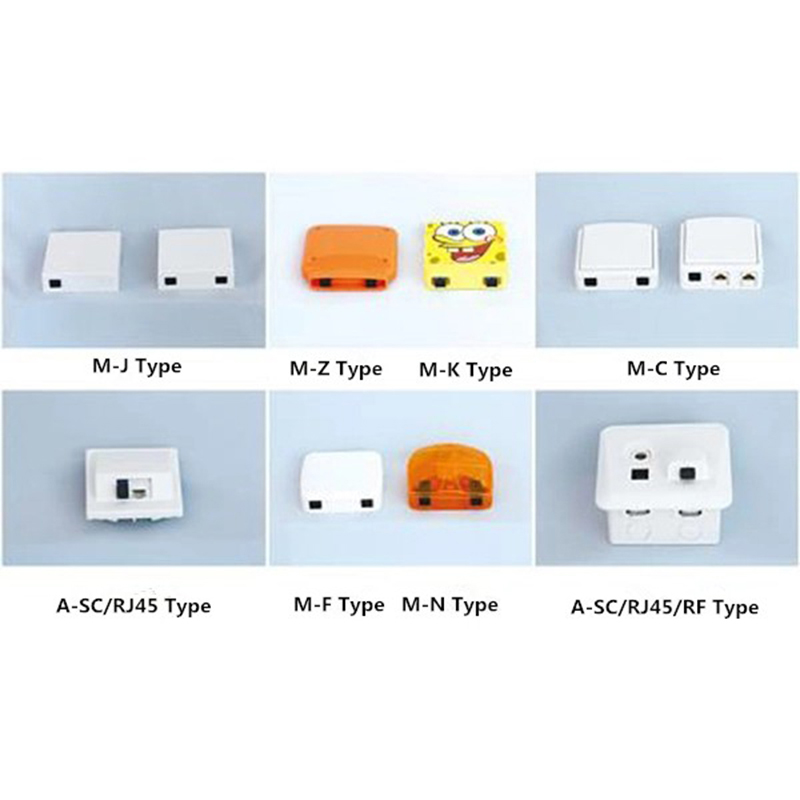
Application:It can be applied to FTTH, FTTO, FTTB applications and also has the functions of splicing, welding and installing connectors. Features:•Large variety; Full specification; Pleasing appearan...
See Details -
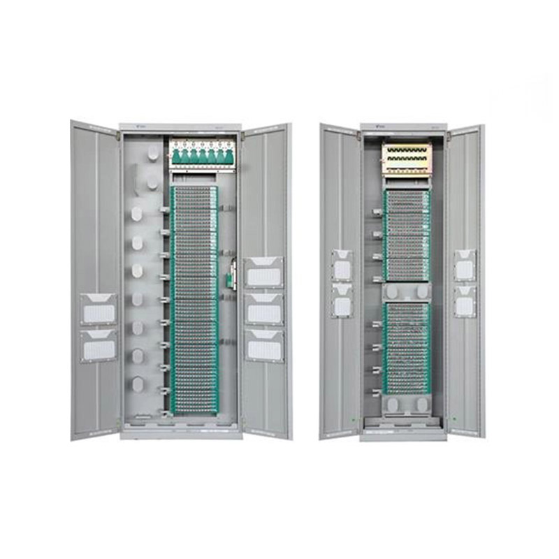
Application ScopeThe GPX129-09T fiber optic distribution frame is used to connect, distribute, and manage fiber optic cables and optical communication equipment. It is suitable for large-capacity fibe...
See Details -
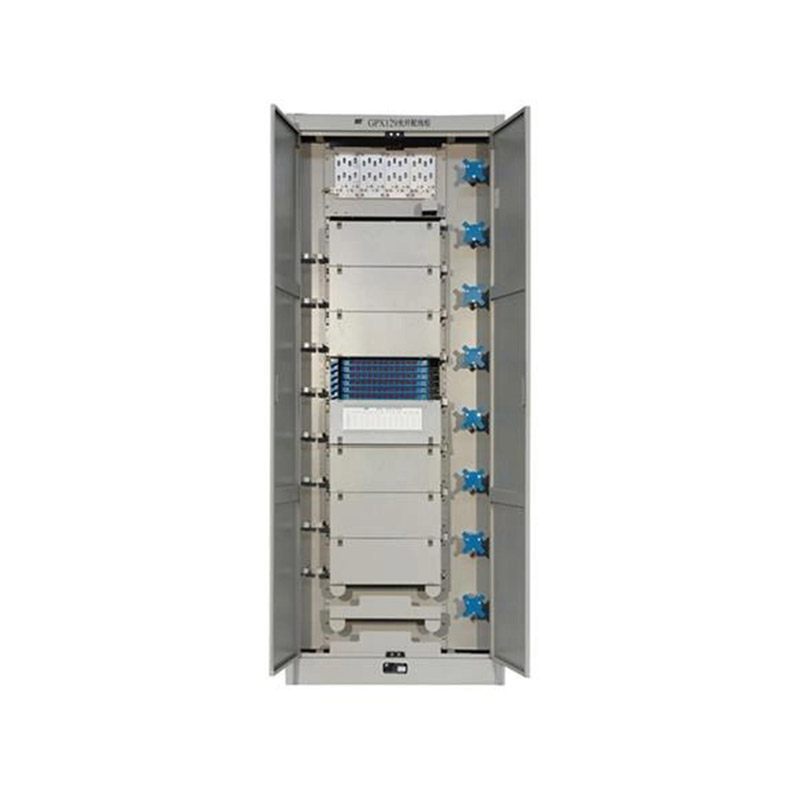
Application ScopeThe GPX129BKC fiber optic distribution frame is used to connect and distribute optical cables to optical communication equipment, and is suitable for large-capacity fiber optic commun...
See Details
Ready to Get started ? Contact Us Now !

Product.
Contact Details.
-
 +86 13958188250
-
 +86 13958188250
-
 [email protected]
-
 AUDIT Email:[email protected]
- Wanma Industrial Park Taihu Yuan Town Lin'an District Hangzhou City China.
QR Code

Copyright © Wanma Technology Co., Ltd. All Rights Reserved.
Privacy
Custom Ethernet Optical Network Railway Transit Equipments Suppliers
