

 English
 Français
 Español
 Português
 عربى
عربى




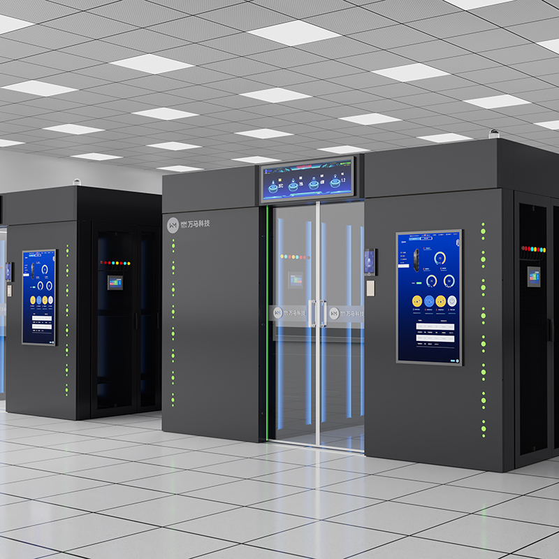
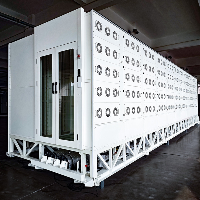
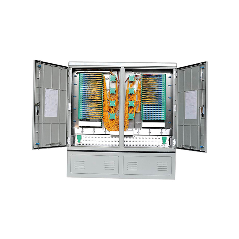

Application1) The Optical Distribution Frame can be installed in a 19-inch standard rack or cabinet.2) The height of the patch panel is 1U, and the modular design is modular.3) The optical fiber adapt...
See DetailsHigh-Density 1U LC Optical Distribution Frame for Modern Fiber Networks
Content
- 1 Product Overview
- 2 Key Specifications
- 3 High-Density Design for Limited Rack Space
- 4 Flexible Capacity Options for Staged Network Growth
- 5 Sliding Tray for Easier Installation and Maintenance
- 6 LC Duplex Interface for Modern Optical Networks
- 7 Fiber Protection and Bend Radius Management
- 8 Strong Mechanical Construction with SPCC Steel
- 9 Advantages Over Conventional Competing Products
- 9.1 Higher Port Density in the Same Rack Space
- 9.2 Better Maintenance Access Through Sliding Tray Design
- 9.3 Capacity Flexibility Across Project Sizes
- 9.4 Integrated Splice and Fiber Storage Management
- 9.5 Strong Material Configuration
- 9.6 Compatibility with OS2, OM3, and OM4 Networks
- 9.7 Professional Appearance and Organized Rack Layout
- 10 Applications in Telecommunications Networks
- 11 Applications in Data Centers and Enterprise Networks
- 12 Applications in Railway Transit Communication Systems
- 13 Manufacturing Strength Behind the Product
- 14 Customization and Integrated Solution Capability
- 15 Role in FTTH and 5G Infrastructure Modernization
- 16 Installation Considerations
- 17 Maintenance and Long-Term Operation
- 18 Ordering Options
- 19 Why This ODF Is a Strong Choice for Network Builders
- 20 Q&A Section
- 20.1 What is the main function of a 1U LC Optical Distribution Frame?
- 20.2 How many cores can this product support?
- 20.3 Why is LC duplex used instead of larger connector types?
- 20.4 Is the frame suitable for both single-mode and multimode networks?
- 20.5 What is the advantage of the pull-out tray?
- 20.6 Why is bend radius management important?
- 20.7 What material is used for the enclosure?
- 20.8 Where can this product be used?
- 20.9 How does this product compare with conventional patch panels?
- 20.10 Can the configuration be customized?
- 21 Conclusion
- 22 References
- 23 Product: 1U 24/48/72/96 Cores LC Optical Distribution Frame
As optical networks expand toward higher bandwidth, lower latency, and denser deployment, the physical layer must become more organized, more compact, and easier to maintain. A 1U 24/48/72/96 Cores LC Optical Distribution Frame is designed for exactly this environment. It gives network builders a rack-mounted platform for fiber termination, splicing, storage, protection, and patching while occupying only 1U of standard 19-inch rack space. For data centers, telecom rooms, central equipment rooms, FTTH infrastructure, enterprise networks, railway transit communication systems, and 5G modernization projects, this type of optical distribution frame provides the foundation for stable, scalable, and high-performance fiber management.
The product is built around a high-density LC duplex interface arrangement and is available in 24-core, 48-core, 72-core, and 96-core configurations. This flexible capacity range allows project planners to choose a model that matches immediate deployment requirements while leaving room for future expansion. Its modular structure, sliding tray, integrated splice management, SPCC steel enclosure, black powder-coated finish, and compatibility with single-mode OS2 and multi-mode OM3/OM4 fiber make it suitable for both carrier-grade and enterprise-level applications.
Compared with conventional patch panels that often provide limited fiber capacity, insufficient cable storage, inconvenient maintenance access, or weak structural protection, this 1U LC optical distribution frame emphasizes density, usability, and long-term reliability. It is not only a passive fiber management product; it is a carefully engineered component that directly affects signal stability, maintenance efficiency, network appearance, and upgrade flexibility.
1U 24/48/72/96 Cores LC Optical Distribution Frame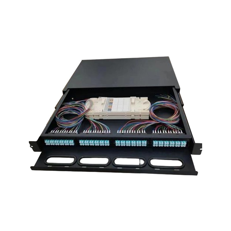
Product Overview
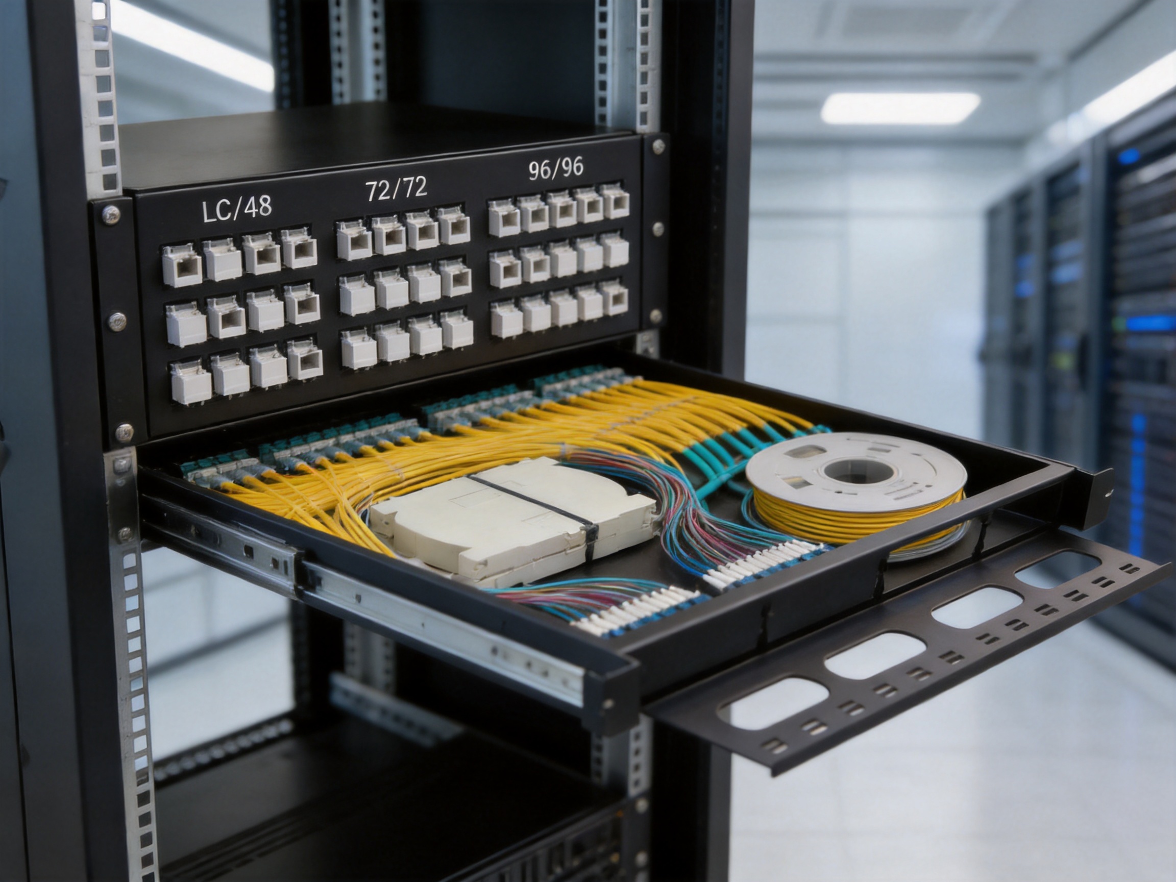
The 1U 24/48/72/96 Cores LC Optical Distribution Frame, also called a 1U LC ODF, is a rack-mount fiber management unit for optical communication networks. It is designed to be installed in a standard 19-inch rack or cabinet and provides organized termination points for optical fiber cables. The front side accommodates LC duplex adapters, while the internal structure provides enough space for pigtails, fiber splicing, fiber routing, and cable storage.
The product adopts a modular design. This allows the same basic enclosure concept to support multiple capacity options. Users can select 24, 48, 72, or 96 cores according to network requirements. For dense fiber networks, the 96-core version provides a significant advantage because it allows a large number of fibers to be managed within a single 1U space. For smaller projects or staged deployment, 24-core and 48-core models offer cost-effective flexibility without overbuilding the rack system.
The LC duplex interface is widely used in modern optical communication infrastructure because of its compact size and stable optical performance. By using LC duplex adapters, the frame can accommodate high fiber density while maintaining an organized front patching area. This is especially valuable in modern racks where space is limited and cable routing must remain clean and readable.
The enclosure is manufactured from SPCC steel, offering mechanical strength and dimensional stability. The body thickness is 1.2 mm, the cover thickness is 1.0 mm, and the mounting bracket thickness is 2.0 mm. These structural choices help the product resist deformation during installation, cable handling, and long-term operation. The black powder-coated outer frame provides corrosion resistance, a clean appearance, and better durability in telecom rooms and equipment cabinets.
The frame contains a fiber splice tray and provides space for fiber splitter arrangement and fiber reel management. This internal space is important because optical fibers must not be bent beyond their recommended radius. Excessive bending can cause insertion loss, reflection, signal attenuation, or long-term fiber damage. By providing a designed routing path and storage area, the ODF helps maintain the required curvature radius throughout the fiber management process.
Key Specifications
Item |
Specification |
Product Name |
1U LC Optical Distribution Frame |
Available Capacity |
24 / 48 / 72 / 96 cores |
Connector Type |
Duplex LC |
Enclosure Type |
19-inch rack mount |
Height |
1U |
Material |
SPCC steel |
Body Thickness |
1.2 mm |
Cover Thickness |
1.0 mm |
Bracket Thickness |
2.0 mm |
Storage Temperature |
-45℃ to +65℃ |
Fiber Compatibility |
Single-mode OS2 and multi-mode OM3 / OM4 |
Configuration |
LC adapters and 12-core bundle type LC pigtails according to capacity demand |
Typical Applications |
Telecom networks, FTTH, 5G infrastructure, data centers, railway transit communication systems, central equipment rooms, enterprise optical networks |
High-Density Design for Limited Rack Space
One of the most important advantages of this product is its ability to support up to 96 cores in only 1U. Rack space is expensive in data centers, central offices, and communication rooms. Every extra rack unit used for passive infrastructure reduces space available for switches, routers, transmission equipment, power distribution units, and other active systems. A high-density ODF directly improves rack utilization.
Traditional low-density optical patch panels may require multiple rack units to manage the same number of fibers. This increases cabinet cost, complicates cabling, and makes future maintenance more difficult. By contrast, the 1U LC ODF provides a dense and compact solution. In 96-core configuration, it can replace several lower-capacity panels, making the rack more efficient and visually organized.
The use of LC duplex adapters is central to this advantage. LC connectors have a small form factor, which enables more ports to be arranged across the front panel without requiring excessive space. Duplex LC adapters support two fibers per adapter position, making them especially suitable for high-density Ethernet, optical transmission, and data communication environments.
High density is not only about placing many ports into a small front panel. It also requires proper internal routing. If the interior is poorly designed, the fibers may become crowded, bent, or difficult to identify. The product addresses this through its internal tray design, splice tray arrangement, and fiber storage space. This allows high density to be achieved without sacrificing fiber protection or operational convenience.
For network operators planning 5G fronthaul, midhaul, and backhaul networks, high-density ODFs can help simplify site construction. Many 5G deployments require increased fiber counts between base stations, aggregation nodes, and equipment rooms. A 1U 96-core LC frame allows more fibers to be terminated and patched within compact cabinets, which is especially valuable in urban locations where equipment space is constrained.
Flexible Capacity Options for Staged Network Growth
Not every project requires 96 cores on day one. Some deployments begin with a small number of active connections and expand as users, devices, or services increase. The availability of 24-core, 48-core, 72-core, and 96-core options makes the product suitable for staged network growth.
A 24-core configuration may be suitable for small enterprise network rooms, branch offices, localized FTTH distribution points, or equipment cabinets with limited fiber counts. A 48-core model can support medium-scale optical distribution, including building backbone networks and access layer applications. A 72-core model offers a balance between higher capacity and manageable deployment scale. The 96-core model is ideal for dense telecom, data center, and metropolitan network applications.
This capacity flexibility gives planners more control over budget and expansion strategy. Instead of purchasing a large frame for a small project or installing multiple low-capacity units for a growing system, the user can choose a model aligned with current needs. At the same time, the consistent product family makes it easier to standardize installation practices across different sites.
Standardization is a major advantage for maintenance teams. When multiple sites use similar rack-mounted ODF structures, technicians can work more efficiently. They understand the tray movement, adapter arrangement, pigtail routing, splice tray location, and labeling approach. This reduces training time and lowers the risk of operational mistakes during installation or troubleshooting.
Sliding Tray for Easier Installation and Maintenance
The product includes a tray that can be pulled out easily through a high-quality slide mechanism. This feature is highly practical in real network environments. Optical fibers require careful handling, and technicians often need clear access to pigtails, splices, adapters, and stored fibers. A fixed internal structure can make maintenance difficult, especially when the ODF is installed among other equipment in a crowded rack.
The sliding tray allows technicians to pull the working area forward. This improves visibility and access without removing the whole frame from the rack. During initial installation, the tray helps with cable preparation, pigtail splicing, adapter connection, and fiber routing. During maintenance, it allows technicians to inspect splices, check cable paths, replace pigtails, or rearrange connections more conveniently.
This design reduces maintenance time and helps avoid accidental fiber stress. When technicians have insufficient access, they may need to bend fibers sharply, pull cables, or work at awkward angles. These actions increase the risk of fiber damage or signal degradation. A smooth pull-out tray creates a more controlled workspace and supports safer handling.
For operators managing many racks or remote sites, maintenance efficiency has direct financial value. Faster access means shorter service windows, reduced labor cost, and lower risk of network interruption. In industries such as rail transit communication, emergency response networks, financial data communication, and carrier access networks, reducing downtime is essential.
LC Duplex Interface for Modern Optical Networks
The optical fiber adapter of the patch panel uses a standardized LC duplex interface. LC connectors are widely adopted because they combine compact size with stable performance. They are suitable for high-speed optical communication systems and are commonly found in Ethernet switches, optical transceivers, passive optical network equipment, and data center infrastructure.
Compared with larger connector types, LC enables greater port density. This is a major reason why the product can reach up to 96 cores in a 1U structure. The duplex format is ideal for transmit-and-receive fiber pairs, which are frequently used in Ethernet and point-to-point optical links.
Standardized LC interfaces also simplify compatibility. Network operators can connect the ODF to common LC patch cords, LC pigtails, LC transceivers, and LC-equipped transmission equipment. This reduces procurement complexity and makes replacement parts easier to source. Compatibility is especially important in projects that involve multiple equipment vendors or phased upgrades over many years.
The product can be configured with LC adapters and 12-core bundle type LC pigtails according to the required capacity. This helps streamline deployment because the frame can be supplied with the necessary internal fiber components. By matching adapters and pigtails to the selected capacity, the user receives a more complete and organized solution rather than a bare enclosure requiring extensive additional sourcing.
Fiber Protection and Bend Radius Management
Optical fiber is highly efficient but also sensitive to improper mechanical handling. Excessive bending, twisting, pulling, or compression can cause optical loss or permanent damage. A professional ODF must therefore do more than hold adapters; it must protect the physical condition of the fiber throughout its path.
This 1U LC ODF contains a fiber splice tray and provides enough space for fiber routing and storage. The design helps ensure that fibers remain within a safe curvature radius. This is particularly important for high-density configurations because more fibers are present in the same enclosure. Without proper routing design, high density can become a disadvantage. Crowded fibers may cross each other randomly, bend sharply, or become difficult to trace.
The internal space supports fiber reel management, pigtail storage, and splice organization. Splice trays keep fusion splices protected and arranged, while routing areas guide fibers from cable entry points to adapters. This supports long-term stability because fibers remain in predictable positions even after maintenance activities.
Bend radius management is also related to signal quality. Macrobending can increase attenuation, especially at longer wavelengths. Microbending caused by pressure points or tight cable ties can also degrade optical performance. By providing a structured fiber management environment, the frame helps maintain low-loss transmission and reduces hidden faults that may otherwise appear after installation.
Strong Mechanical Construction with SPCC Steel
The enclosure is made from SPCC steel, a material commonly used for precision sheet metal products that require strength, formability, and dimensional consistency. For rack-mounted telecom equipment, enclosure strength is important because the product must withstand installation forces, cable loads, repeated tray operation, and long-term cabinet conditions.
The frame uses different material thicknesses according to structural requirements. The body is 1.2 mm thick, giving the main enclosure rigidity. The cover is 1.0 mm thick, balancing protection with manageable weight. The mounting bracket is 2.0 mm thick, providing stronger support at the rack connection points. This combination helps ensure that the ODF remains stable when installed in a 19-inch rack.
Compared with lightweight or poorly reinforced panels, this stronger construction reduces deformation risk. Deformation can create alignment issues, affect tray movement, stress adapters, or make rack installation difficult. A robust enclosure also gives technicians confidence when handling the unit during installation and maintenance.
The black powder-coated surface improves corrosion resistance and appearance. Powder coating creates a durable finish that can resist scratches, oxidation, and normal handling wear better than many simple painted finishes. In telecom rooms and data centers, a neat and uniform black finish also improves the professional appearance of the rack system.
Mechanical quality is often overlooked in passive fiber products, but it directly affects service life. An ODF may remain in operation for many years while active equipment around it is upgraded several times. A strong and well-finished enclosure protects the investment and helps preserve the physical layer through multiple network technology cycles.
Advantages Over Conventional Competing Products
In the optical distribution frame market, many products appear similar at first glance. However, real differences become clear during installation, high-density operation, and long-term maintenance. The 1U 24/48/72/96 Cores LC Optical Distribution Frame offers several competitive advantages.
Higher Port Density in the Same Rack Space
Some competing patch panels offer only 12, 24, or 48 cores in 1U. For small systems this may be acceptable, but for modern fiber-intensive networks it leads to rapid rack consumption. The ability to reach up to 96 cores in 1U gives this product a density advantage. It helps users reduce the number of rack units required, simplify cabinet layouts, and improve the scalability of optical distribution points.
Better Maintenance Access Through Sliding Tray Design
Many low-cost ODFs use fixed trays or limited-access internal structures. This can make splicing and troubleshooting inconvenient. The pull-out tray of this product improves access and reduces the risk of fiber damage during service. For network operators, this is not just a convenience feature; it can reduce maintenance time and improve operational reliability.
Capacity Flexibility Across Project Sizes
A product family covering 24, 48, 72, and 96 cores provides broader application flexibility than a single-capacity solution. Users can standardize on one design style while choosing different capacities for different sites. This is an advantage over competitors that require separate product types for different density levels.
Integrated Splice and Fiber Storage Management
Some patch panels focus only on adapter presentation and leave limited room for splicing or storage. This product includes a splice tray and enough space for fiber routing and fiber reel management. That makes it suitable for real installation scenarios where incoming cables must be spliced to pigtails and stored safely.
Strong Material Configuration
The use of SPCC steel with specified body, cover, and bracket thickness gives the product structural credibility. Thin, weak, or poorly finished enclosures may reduce cost initially but can create problems over time. A stronger enclosure improves rack stability, tray function, and long-term durability.
Compatibility with OS2, OM3, and OM4 Networks
The frame supports single-mode OS2 and multi-mode OM3/OM4 fiber configurations. This makes it useful across many network types, from long-distance single-mode transmission to high-speed multimode data center links. Competitors with narrower fiber compatibility may require different products for different projects.
Professional Appearance and Organized Rack Layout
The black powder-coated finish, rack-mount format, LC front interface, and internal cable organization contribute to a clean and professional installation. In complex equipment rooms, appearance is not merely aesthetic. Clear and organized cabling supports faster troubleshooting and reduces human error.
Applications in Telecommunications Networks
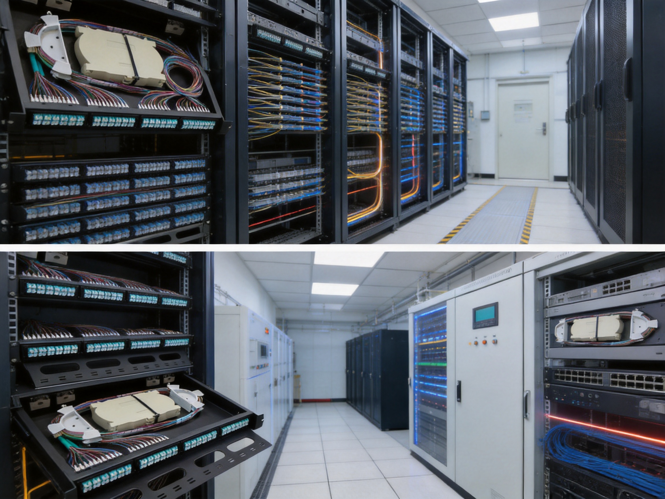
Telecommunications networks depend on reliable optical fiber infrastructure. Whether used in central offices, access networks, aggregation points, or transmission rooms, an ODF provides the physical interface between outside plant cables and active optical equipment. The 1U LC ODF is especially suitable for telecom applications because it combines density, protection, and standardized LC connectivity.
In central equipment rooms, large volumes of fiber links may connect routers, optical transport systems, switches, and external cable routes. High-density ODFs help manage these connections in a compact and readable way. The 96-core capacity option is useful when many circuits must be terminated in limited rack space.
In access network deployments, the frame can support fiber-to-the-home and fiber-to-the-building architectures. Operators can use it to terminate distribution fibers, connect pigtails, and patch services toward optical line terminals or aggregation devices. Because the product supports different capacities, it can be selected according to the size of the neighborhood, building, or distribution node.
For 5G network modernization, fiber connectivity becomes even more important. 5G sites require high-capacity backhaul and, in some architectures, extensive fronthaul fiber. Compact ODFs help organize these connections in base station equipment rooms, edge data centers, and aggregation cabinets. A dense 1U solution supports network scaling without excessive cabinet expansion.
Applications in Data Centers and Enterprise Networks
Data centers require structured cabling systems that support high bandwidth, quick changes, and reliable documentation. The 1U LC Optical Distribution Frame can be used as part of the fiber patching infrastructure between switches, storage systems, servers, interconnect equipment, and external carrier links.
LC duplex connectivity is widely used with optical transceivers, making the frame compatible with many common data center architectures. The high-density design helps reduce the amount of rack space consumed by passive cabling hardware. This is important because data center racks are often planned carefully around power, cooling, cable pathways, and equipment density.
Enterprise networks also benefit from organized fiber distribution. Campus networks, hospitals, universities, industrial parks, transportation hubs, and office complexes often use fiber backbones between buildings and communication rooms. A rack-mounted ODF provides a clean termination and patching point, helping IT teams manage backbone links with less confusion.
Because the product can support both single-mode and multimode fiber types, it can be adapted to different enterprise requirements. Single-mode OS2 may be selected for long-distance building interconnection, while OM3 or OM4 multimode may be selected for shorter high-speed links inside facilities.
Applications in Railway Transit Communication Systems
Railway and urban transit systems require highly reliable communication networks. Signaling, surveillance, passenger information systems, dispatching, control systems, and operational data transmission all depend on stable connectivity. Optical fiber is widely used in these environments because it supports long distance, high bandwidth, and electromagnetic interference resistance.
A 1U LC ODF can be installed in station communication rooms, control centers, line-side equipment rooms, and cabinet systems. Its rack-mounted structure and strong enclosure support professional deployment in infrastructure environments. The high-density capacity is useful when many communication subsystems require fiber termination within limited equipment room space.
The product’s fiber protection design is particularly important in transit systems, where maintenance access may be constrained and service continuity is critical. A sliding tray helps technicians perform inspection or adjustments without disturbing adjacent equipment. Organized splice and storage management reduces the chance of accidental disconnection or fiber damage.
In rail transit projects, long product life and stable manufacturing quality are essential. Passive optical components may be expected to remain in service for many years. Therefore, structural strength, corrosion-resistant finishing, precise adapter placement, and dependable assembly are important selection criteria.
Manufacturing Strength Behind the Product
The quality of an optical distribution frame depends heavily on manufacturing capability. A well-designed product can only perform reliably if it is produced with controlled processes, accurate metalwork, consistent finishing, careful assembly, and strict quality inspection. Wanma Technology Co., Ltd. has manufacturing experience in communication cabinets, communication electronic equipment, and passive optical components. Since its establishment in 1997, the company has developed products for optical communication networks, Ethernet networks, central equipment rooms, national high-speed railway systems, and urban rail transit systems.
This background is important because the 1U LC ODF is not an isolated product. It belongs to a broader ecosystem of telecom physical infrastructure. Experience in cabinets, electronic communication equipment, and passive optical components allows the manufacturer to understand how the ODF fits into real network installations. Rack compatibility, cable routing, enclosure durability, fiber management, and project customization are all influenced by this practical industry experience.
Precision Sheet Metal Processing
The enclosure requires accurate cutting, forming, punching, and bending. Adapter ports must align properly, rack mounting ears must fit standard 19-inch cabinets, and the sliding tray must move smoothly. Precision sheet metal processing helps ensure that these dimensions remain consistent from one unit to another.
Accurate sheet metal work also affects assembly efficiency. If panels are misaligned or holes are inaccurate, the product may require rework or may not fit correctly in the rack. A mature manufacturing process reduces these risks and supports stable batch production.
Durable Surface Treatment
The black powder-coated finish is more than a visual feature. Powder coating requires surface preparation, controlled coating application, curing, and inspection. A uniform coating helps protect the SPCC steel from corrosion and handling damage. It also gives the product a professional appearance suitable for modern equipment rooms.
Compared with weak finishing processes, high-quality powder coating improves long-term durability. This matters in environments where equipment may be installed for years and exposed to temperature variation, humidity, dust, or frequent technician handling.
Controlled Assembly of Adapters and Pigtails
The ODF can be configured with LC adapters and 12-core bundle type LC pigtails according to capacity demand. Assembly quality affects optical performance and maintenance convenience. Adapters must be securely fixed, pigtails must be routed properly, and splice trays must be arranged for easy access.
Controlled assembly helps ensure that the internal fiber paths are clean and predictable. It also supports capacity customization, allowing the product to be delivered in different configurations for OS2, OM3, and OM4 networks.
Quality Inspection and Practical Reliability
Quality inspection for an ODF should include mechanical appearance, dimensional conformity, adapter installation, tray movement, coating quality, accessory completeness, and packaging protection. For configured units, optical component quality and pigtail arrangement are also important.
Manufacturing strength is reflected in repeatability. A buyer does not need one good sample; the buyer needs every delivered unit to meet the same standard. Consistency reduces installation surprises and helps large projects progress on schedule.

Customization and Integrated Solution Capability
Modern communication projects often require more than standard catalog products. Cabinet dimensions, fiber counts, connector types, cable entry directions, labeling requirements, color preferences, accessory packages, and application environments may vary. A manufacturer with integrated solution capability can help adapt products to project needs.
Wanma Technology Co., Ltd. develops, manufactures, and markets its own branded products while also providing integrated solutions for customized products. This is an advantage for project contractors, telecom operators, and system integrators who need reliable supply and technical coordination. Instead of sourcing separate components from multiple suppliers, they can work with a manufacturer familiar with the full communication infrastructure environment.
Customization capability may include different capacity configurations, pigtail types, adapter colors, packaging requirements, special labeling, cabinet integration, and project-specific accessory kits. For international projects, the ability to support different network standards and application habits can also be valuable.
The company’s sales network covers more than 20 countries and regions, including the United States, Australia, the United Kingdom, Italy, South Africa, and Ghana. This international presence indicates experience with diverse customer expectations, project requirements, and delivery conditions. For buyers, global supply experience can provide confidence in communication, logistics coordination, and long-term cooperation.
Role in FTTH and 5G Infrastructure Modernization
Fiber-to-the-home and 5G modernization are two major drivers of optical network expansion. Both require dense and reliable fiber management. FTTH networks bring optical fiber closer to end users, increasing the number of distribution points, splicing locations, and patching interfaces. 5G networks require high-capacity connections between radio sites, edge nodes, and core networks.
The 1U LC ODF is well suited for these modernization trends. In FTTH infrastructure, it can be used in central offices, building equipment rooms, aggregation cabinets, and distribution nodes. Its splice tray supports pigtail splicing, while the LC adapter front panel provides a convenient patching interface.
In 5G infrastructure, the frame helps organize high-volume optical links. As networks evolve toward cloud radio access networks, edge computing, and higher-capacity transport, physical fiber management becomes more complex. Dense ODFs reduce space pressure and make network changes easier to manage.
Modernization projects also require products that can be deployed repeatedly across many sites. The 24/48/72/96 capacity range supports this need. A single product family can be used for small, medium, and large sites, simplifying procurement and maintenance standards.
Installation Considerations
Proper installation is essential to obtain the full benefit of the product. The ODF should be installed in a standard 19-inch rack or cabinet using suitable mounting hardware. The rack should provide enough front and rear working space for cable routing and maintenance access. Incoming optical cables should be secured to prevent pulling force from being transferred to splices or adapters.
During installation, technicians should prepare cables carefully and maintain the recommended bend radius. Fibers should be routed through the internal management paths and stored neatly in the splice tray or fiber storage area. Pigtails should not be twisted or compressed. Cable ties, if used, should be applied gently and should not create pressure points.
Labeling is also important. Each adapter port should be identified clearly according to the network design. Good labeling reduces troubleshooting time and lowers the risk of incorrect patching. For high-density 72-core or 96-core units, labeling becomes especially important because many connections are located in a compact area.
After splicing and patching, optical performance should be tested using suitable instruments. Insertion loss, continuity, and route identification should be verified according to project requirements. The tray should be pushed back carefully after confirming that no fiber is pinched or bent sharply.
Maintenance and Long-Term Operation
A well-designed ODF supports long-term network operation by making maintenance easier and safer. The sliding tray allows technicians to access internal components without removing the unit from the rack. This helps during inspection, cleaning, connector replacement, pigtail adjustment, and troubleshooting.
Connector cleanliness is critical in optical networks. Dust or contamination on LC connector end faces can cause signal loss or reflection. Maintenance teams should follow proper cleaning procedures before connecting patch cords. Dust caps should be used when ports are not connected.
Fiber records should be kept updated. Every patching change should be documented to prevent confusion. In high-density installations, undocumented changes can quickly create operational risk. A clean ODF layout and clear labeling system make documentation easier to maintain.
The enclosure should also be inspected periodically for mechanical damage, loose screws, blocked tray movement, or cable stress. The powder-coated SPCC steel structure is durable, but normal inspection helps ensure that the physical layer remains reliable over years of use.
Ordering Options
The product family includes single-mode OS2 and multi-mode OM3 ordering options for several capacity levels. The correct choice depends on the network type, transmission distance, equipment interface, and project design. OS2 is typically used for longer-distance single-mode links, while OM3 and OM4 are used for high-speed multimode applications over shorter distances.
Model |
Description |
WM-ODF-24LC-OS2 |
24-core LC single-mode OS2 fiber optic distribution frame |
WM-ODF-24LC-OM3 |
24-core LC multi-mode OM3 fiber optic distribution frame |
WM-ODF-48LC-OS2 |
48-core LC single-mode OS2 fiber optic distribution frame |
WM-ODF-48LC-OM3 |
48-core LC multi-mode OM3 fiber optic distribution frame |
WM-ODF-72LC-OS2 |
72-core LC single-mode OS2 fiber optic distribution frame |
WM-ODF-72LC-OM3 |
72-core LC multi-mode OM3 fiber optic distribution frame |
WM-ODF-96LC-OS2 |
96-core LC single-mode OS2 fiber optic distribution frame |
WM-ODF-96LC-OM3 |
96-core LC multi-mode OM3 fiber optic distribution frame |
Although the listed options include OS2 and OM3, the product can also support OM4 fiber according to capacity and configuration requirements. Buyers should confirm the required fiber type, connector polish type, adapter color, pigtail length, and packaging accessories before ordering.
Why This ODF Is a Strong Choice for Network Builders
Network builders need products that combine performance, usability, reliability, and cost efficiency. The 1U 24/48/72/96 Cores LC Optical Distribution Frame addresses these needs through high-density capacity, flexible configuration, mechanical strength, and practical fiber management.
Its strongest value is the combination of 1U space efficiency and up to 96-core capacity. This helps users build dense optical networks without consuming unnecessary rack space. The LC duplex interface supports modern network equipment and high-density patching. The sliding tray improves maintenance access, while the internal splice tray and fiber storage area protect fibers from harmful bending and disorganization.
The SPCC enclosure and powder-coated finish provide physical durability. The ability to support OS2, OM3, and OM4 networks makes the product adaptable across telecom, data center, enterprise, FTTH, 5G, and rail transit applications. When paired with a manufacturer that has long-term communication infrastructure experience and integrated solution capability, the product becomes a dependable element of modern optical network construction.
For buyers comparing passive fiber management products, it is important to look beyond simple port count and price. A lower-cost panel with weak tray access, poor cable storage, thin material, or limited configuration flexibility may create higher costs later through installation delays, signal problems, maintenance difficulty, or premature replacement. A professionally designed ODF supports the entire life cycle of the network.
Q&A Section
What is the main function of a 1U LC Optical Distribution Frame?
A 1U LC Optical Distribution Frame is used to terminate, splice, store, protect, and patch optical fibers in a standard 19-inch rack or cabinet. It provides a structured interface between incoming optical cables and network equipment.
How many cores can this product support?
The product is available in 24-core, 48-core, 72-core, and 96-core configurations. The maximum capacity is 96 cores in a 1U rack-mount enclosure.
Why is LC duplex used instead of larger connector types?
LC duplex connectors provide a compact interface suitable for high-density optical networks. Their small form factor allows more ports to fit into a 1U panel while remaining compatible with many modern optical transceivers and patch cords.
Is the frame suitable for both single-mode and multimode networks?
Yes. The frame can support single-mode OS2 fiber and multi-mode OM3/OM4 fiber configurations. This makes it useful for long-distance telecom links as well as high-speed data center and enterprise applications.
What is the advantage of the pull-out tray?
The pull-out tray improves access during installation and maintenance. Technicians can reach splices, pigtails, adapters, and stored fibers more easily, reducing service time and lowering the risk of damaging fibers.
Why is bend radius management important?
Optical fibers can suffer increased attenuation or permanent damage if bent too sharply. The internal structure of the ODF provides organized routing and storage space to help maintain a safe bend radius.
What material is used for the enclosure?
The enclosure is made from SPCC steel. The body is 1.2 mm thick, the cover is 1.0 mm thick, and the bracket is 2.0 mm thick. This supports stable rack installation and long-term durability.
Where can this product be used?
It can be used in telecom networks, FTTH systems, 5G infrastructure, data centers, enterprise networks, central equipment rooms, railway communication systems, and urban rail transit projects.
How does this product compare with conventional patch panels?
It offers higher density, a sliding tray for easier maintenance, better internal fiber storage, flexible capacity options, a durable SPCC steel enclosure, and compatibility with multiple fiber types. These advantages make it more suitable for modern high-density networks.
Can the configuration be customized?
Yes. Capacity, fiber type, adapter and pigtail configuration, labeling, and accessory requirements can be selected according to project needs. The manufacturer also has experience providing integrated communication infrastructure solutions.
Conclusion
The 1U 24/48/72/96 Cores LC Optical Distribution Frame is a compact, high-density, and practical solution for modern fiber management. It brings together the essential features that network operators and system integrators require: LC duplex connectivity, 24 to 96 core capacity, rack-mount installation, a pull-out tray, integrated splice management, safe fiber routing, SPCC steel construction, powder-coated protection, and compatibility with OS2, OM3, and OM4 fiber networks.
Its advantages are especially clear in space-constrained and fiber-intensive environments. By supporting up to 96 cores in 1U, it helps optimize rack usage. By offering a sliding tray and internal storage structure, it simplifies installation and maintenance. By using durable materials and professional manufacturing processes, it supports long-term operation in demanding communication environments.
Behind the product is the manufacturing experience of Wanma Technology Co., Ltd., a company established in 1997 with expertise in communication cabinets, communication electronic equipment, and passive optical components. Its products are used in Ethernet networks, optical communication networks, central equipment rooms, national high-speed railways, and urban rail transit systems. This background strengthens the product’s value for buyers who need dependable manufacturing, customized solutions, timely delivery, and long-term cooperation.
For telecommunications operators, data center planners, enterprise IT teams, FTTH contractors, 5G infrastructure builders, and rail transit communication projects, this 1U LC ODF provides an efficient physical layer platform. It is a small rack-mounted product with a large impact on network organization, reliability, and future scalability.
References
1. International Electrotechnical Commission. Optical Fibres, Cables and Connector Standards for Telecommunication Networks.
2. Telecommunications Industry Association. Generic Telecommunications Cabling for Customer Premises.
3. International Organization for Standardization and International Electrotechnical Commission. Information Technology Generic Cabling for Customer Premises.
4. Fiber Optic Association. Reference Guide to Fiber Optics and Premises Cabling.
5. ITU-T. Optical Fibre Cable and Components Recommendations for Telecommunication Systems.
6. BICSI. Telecommunications Distribution Methods Manual.
Product: 1U 24/48/72/96 Cores LC Optical Distribution Frame
PREV:High-Value Consumables House: A Digital Management Hub for Safer Medical Supply Control
NEXT:Electronic Fence for Intelligent Clean-Area Access and Uniform Management
NEXT:Electronic Fence for Intelligent Clean-Area Access and Uniform Management
Interested in cooperation or have questions?
Related products
-
-
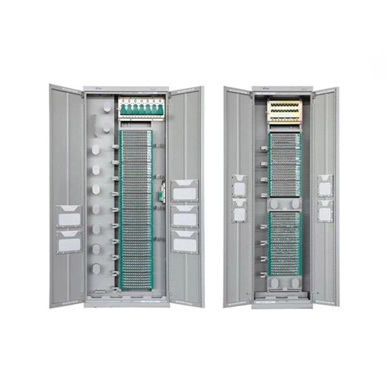
Application ScopeThe GPX129-09T fiber optic distribution frame is used to connect, distribute, and manage fiber optic cables and optical communication equipment. It is suitable for large-capacity fibe...
See Details -
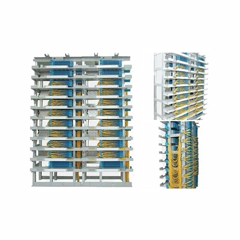
Application Used in independent fiber patching areas of newly built communication equipment rooms and central equipment rooms. After cable removal, the original main distribution frame is dismantled, ...
See Details -
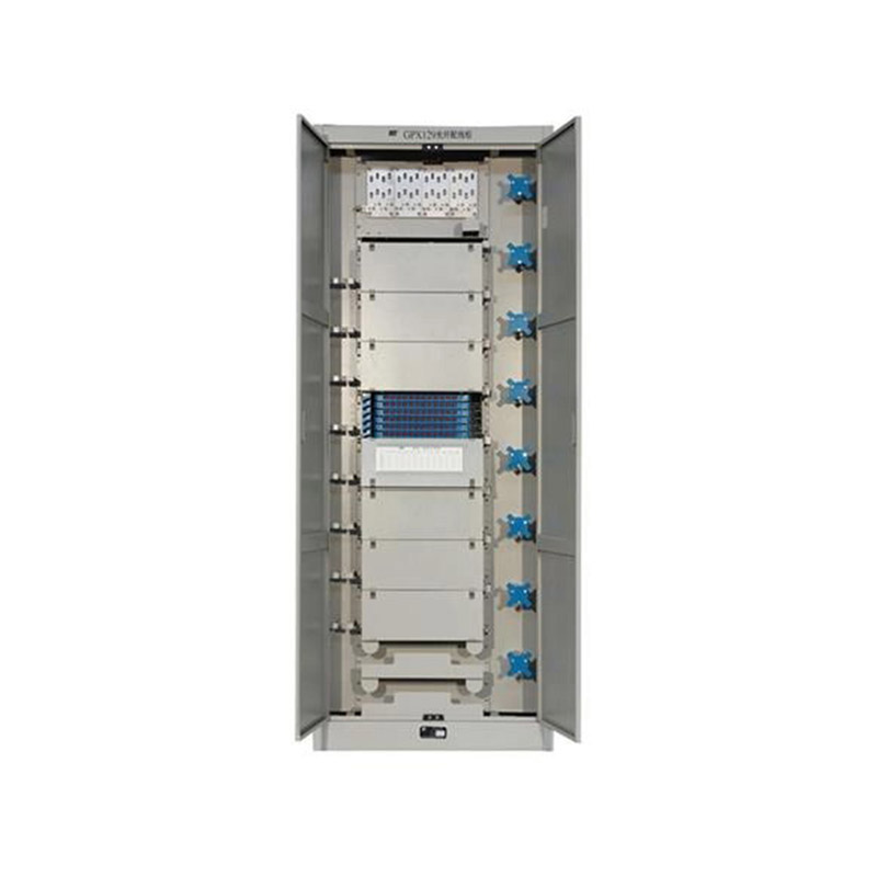
Application ScopeThe GPX129BKC fiber optic distribution frame is used to connect and distribute optical cables to optical communication equipment, and is suitable for large-capacity fiber optic commun...
See Details
Ready to Get started ? Contact Us Now !

Product.
Contact Details.
-
 +86 13958188250
-
 +86 13958188250
-
 [email protected]
- Wanma Industrial Park Taihu Yuan Town Lin'an District Hangzhou City China.
QR Code

Copyright © Wanma Technology Co., Ltd. All Rights Reserved.
Custom Ethernet Optical Network Railway Transit Equipments Suppliers
