

 English
 Français
 Español
 Português
 عربى






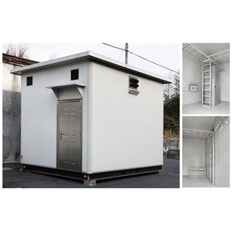

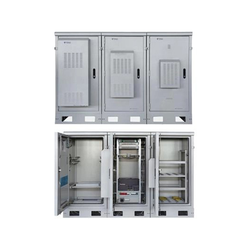
Application:Outdoor Signal Control Cabinets are widely used in the subway signal control system. Features:Material: Galvanized steel or Stainless steel.Protection Level: IP55Color: RAL7035 Gray
See DetailsOutdoor Railway Signal Control Cabinets: EMC Protection, Manufacturing Quality, and Trackside Reliability
Content
- 1 1. The Role of an Outdoor Signal Control Cabinet in Railway Systems
- 2 2. Product Configuration and Main Characteristics
- 3 3. Why Railway EMC Protection Matters
- 4 4. Performance Advantages Compared with Ordinary Industrial Cabinets
- 5 5. Advanced Manufacturing Process
- 5.1 5.1 Engineering Review and Project Specification
- 5.2 5.2 Precision Sheet Metal Fabrication
- 5.3 5.3 Welding and Structural Assembly
- 5.4 5.4 Surface Preparation and Coating
- 5.5 5.5 Gasket, Door, and Locking Assembly
- 5.6 5.6 Internal Mounting and Wiring Organization
- 5.7 5.7 Inspection and Functional Verification
- 6 6. Design Features That Support Long-Term Outdoor Service
- 7 7. Customization for Railway Transit Projects
- 8 8. Manufacturing Strength and Integrated Supply Capability
- 9 9. Quality, Delivery, and Lifecycle Value
- 10 10. Recommended Selection Criteria
- 11 11. Installation and Maintenance Recommendations
- 12 12. Frequently Asked Questions
- 12.1 Q1. Can a standard industrial control cabinet be used beside railway tracks?
- 12.2 Q2. What materials are available for the outdoor signal control cabinet?
- 12.3 Q3. What does IP55 mean for this cabinet?
- 12.4 Q4. Why are shielding and grounding both necessary?
- 12.5 Q5. Can the cabinet include communication equipment?
- 12.6 Q6. Can the internal layout be customized?
- 12.7 Q7. Is grounding the cabinet to the rail sufficient?
- 12.8 Q8. How can condensation be controlled?
- 12.9 Q9. How often should surge protection devices be replaced?
- 12.10 Q10. What information should be provided for a customized quotation?
- 13 13. Conclusion
- 14 References
- 15 Product: Outdoor Signal Control Cabinet
Outdoor signal control cabinets are essential enclosures in railway signaling, subway infrastructure, urban rail transit, and other trackside communication systems. They protect relays, programmable logic controllers, power supplies, terminal blocks, network equipment, signal interfaces, and surge protection devices from weather, electromagnetic interference, mechanical impact, and unauthorized access.
Unlike ordinary industrial enclosures, a railway signal control cabinet must perform reliably in an electrically aggressive and environmentally demanding location. It may be installed beside electrified tracks, close to traction substations, exposed to lightning, and subjected to wide temperature changes, dust, moisture, vibration, and maintenance activity. A cabinet that only provides physical protection is not sufficient. It must also control electromagnetic coupling, manage heat, maintain grounding continuity, and support safe and efficient field maintenance.
The outdoor signal control cabinet described in this article is designed for subway signal control systems and railway transit applications. It is available in galvanized steel or stainless steel, uses an IP55 protection design, and is commonly finished in RAL7035 gray. Its value is not limited to the strength of the enclosure. The complete product concept combines robust materials, controlled fabrication, EMC protection, practical internal organization, and customized manufacturing support.
1. The Role of an Outdoor Signal Control Cabinet in Railway Systems
Railway signaling depends on the accurate transfer and processing of information. Track circuits, axle counters, switch machines, platform systems, interlocking equipment, train detection systems, and supervisory control systems must exchange signals without unintended interruption. The outdoor cabinet forms the physical and electrical interface between these field devices and the protected control equipment inside.
In a typical installation, the cabinet may contain terminal blocks for incoming field cables, circuit breakers, low-voltage power distribution, relays, isolation modules, fiber or copper communication equipment, PLC or remote I/O units, grounding bars, and surge protection devices. The cabinet may also provide separate compartments for power circuits and sensitive signal circuits.
Proper separation is important because power switching and traction-related disturbances can create unwanted currents in signal wiring. If these currents reach a relay coil, input module, or communications interface, they may cause data errors, equipment resets, false indications, or unintended switching. The cabinet therefore has to support both mechanical protection and system-level electromagnetic compatibility.
Trackside installation also creates special environmental requirements. The enclosure must prevent rainwater and dust from entering during normal operation. It must withstand sunlight, wind, temperature cycling, condensation, and routine cleaning. It should provide a stable platform for equipment while allowing technicians to inspect, test, replace, and reconfigure components safely.
2. Product Configuration and Main Characteristics
2.1 Galvanized Steel or Stainless Steel Construction
The cabinet can be manufactured from galvanized steel or stainless steel according to project conditions, budget, corrosion exposure, and customer preference. Galvanized steel provides a strong and economical solution for many railway and subway installations. The zinc coating improves resistance to atmospheric corrosion and helps protect areas where the steel is exposed during normal service.
Stainless steel is suitable for locations with higher humidity, salt exposure, aggressive industrial atmospheres, coastal conditions, or demanding lifecycle requirements. It can also be selected where a particularly high level of corrosion resistance and surface durability is required.
The choice between galvanized steel and stainless steel should be made after reviewing the installation environment. Important considerations include local rainfall, proximity to the sea, deicing chemicals, pollution levels, cleaning agents, expected service life, and maintenance practices. Offering both materials enables the cabinet to be adapted rather than forcing every project into a single standard configuration.
2.2 IP55 Protection
The cabinet is designed around an IP55 protection level. The first digit indicates protection against dust that could interfere with the satisfactory operation of the equipment. The second digit indicates protection against water jets from any direction. This makes the enclosure suitable for many outdoor industrial and railway environments when installed and maintained correctly.
IP55 performance depends on the complete enclosure assembly, not simply on the cabinet body. Doors, hinges, locks, cable entry plates, ventilation components, joints, and sealing gaskets must work together. Correct installation is equally important. Cable glands must be properly tightened, unused openings must be sealed, and doors must be closed evenly to maintain gasket compression.
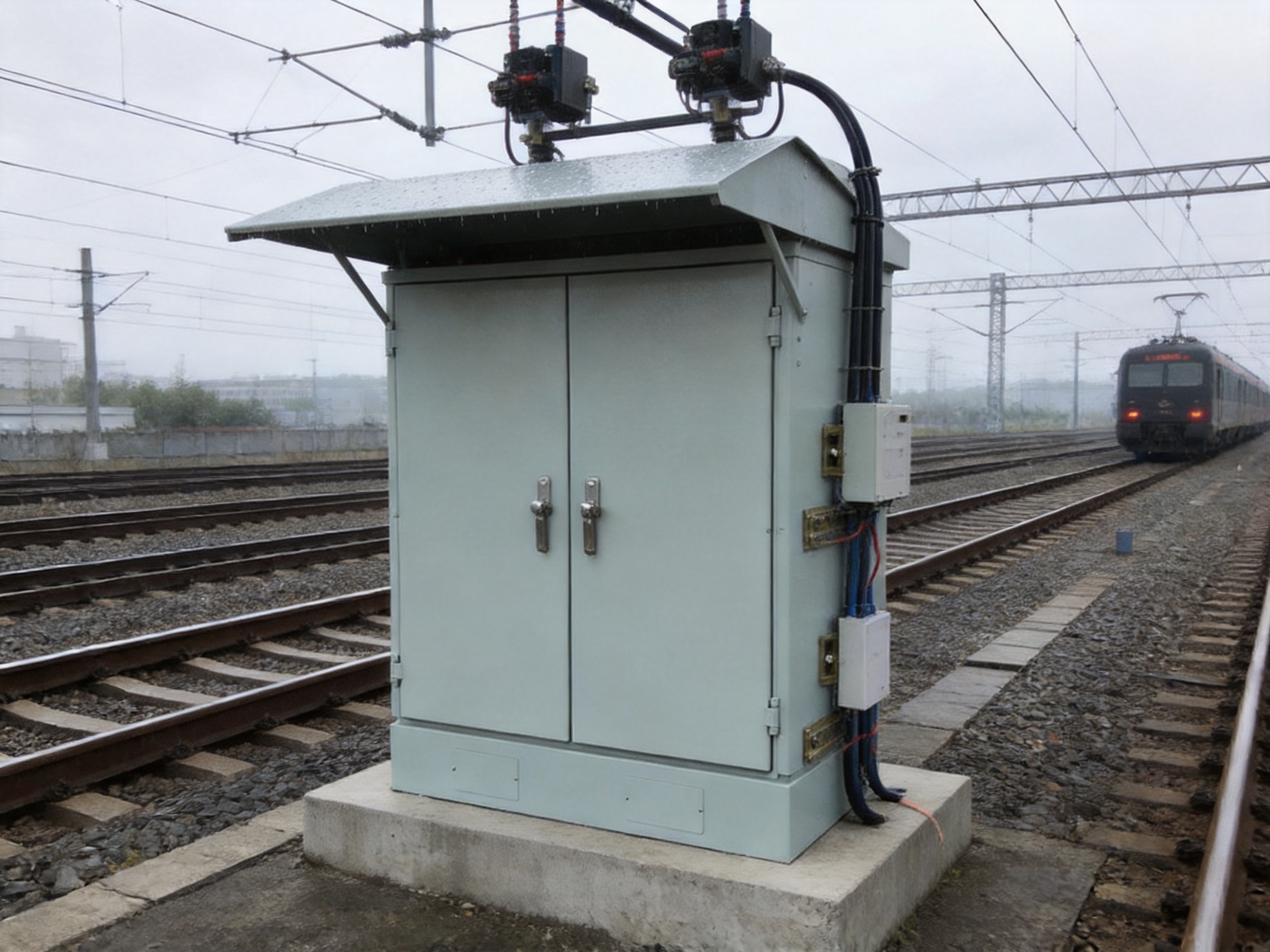
For locations with special exposure, additional measures may be specified. These can include rain canopies, sloped roofs, anti-condensation heaters, thermostatic control, filtered ventilation, sun shields, raised plinths, or stainless-steel hardware. Such options can be integrated into the design according to the project requirements.
2.3 RAL7035 Gray Finish
RAL7035 gray is widely used for industrial and railway equipment because it provides a neutral, professional appearance and is compatible with many infrastructure environments. A properly prepared and coated surface can improve resistance to corrosion, abrasion, ultraviolet exposure, and routine handling.
The surface treatment may include degreasing, cleaning, pretreatment, powder coating, curing, and inspection. Coating thickness, adhesion, color consistency, and surface defects should be controlled during manufacturing. Areas around mounting points, hinges, door edges, and cable openings require particular attention because poor treatment in these areas can accelerate corrosion or reduce mechanical performance.
3. Why Railway EMC Protection Matters
Railway environments are exposed to stronger electromagnetic disturbances than many conventional industrial installations. Traction systems can produce large return currents, switching transients, harmonic components, and magnetic fields. Lightning can create high-energy surge conditions on power and signal cables. Nearby radio transmitters, switching power supplies, and other railway equipment can also contribute to the electromagnetic environment.
Traction return currents can reach very high values during train acceleration. The resulting magnetic field may couple into wiring loops, relay circuits, and analog signal paths. Lightning strikes, whether direct or nearby, can induce substantial voltages in long outdoor cables. Even when a surge does not destroy a component, it may cause temporary malfunction, memory corruption, communication interruption, or an incorrect signal state.
In railway signaling, a short interruption can be operationally significant. An incorrect indication may cause unnecessary service delays, repeated equipment resets, or a failure to detect a field condition. More seriously, inadequate protection can increase the risk of false relay operation or unintended control commands. For this reason, EMC design must be considered from the beginning of the cabinet engineering process.
3.1 Continuous Metallic Shielding
A metallic enclosure helps reduce the penetration of radiated electromagnetic energy. Galvanized steel or stainless steel cabinet walls create a conductive barrier around the internal equipment. The shielding effect depends on material properties, wall thickness, seams, door construction, openings, cable interfaces, and grounding arrangements.
For demanding railway applications, cabinet panels can be designed with controlled aperture areas and reinforced seams. Doors should maintain electrical continuity with the enclosure. Conductive finger strips or equivalent bonding components can be used around door edges to maintain a low-impedance connection when the door is closed. This is especially important at higher frequencies, where small gaps can behave as unintended antennas.
Shielding must also extend to cable entry points. A cabinet with excellent walls can still have poor EMC performance if signal cables enter through large unsealed openings or if cable shields are terminated incorrectly. Cable glands, shield clamps, bonding plates, and grounding terminals should therefore be selected as part of the complete EMC design.
3.2 Filtered Power Entry
Power cables can conduct disturbances into the cabinet. Multi-stage filters may be used to reduce common-mode and differential-mode noise over the relevant frequency range. These filters are designed to attenuate unwanted high-frequency energy while allowing the required operating power to pass to the internal equipment.
Filter selection depends on voltage, current, frequency, leakage current, short-circuit conditions, installation category, and the sensitivity of the connected devices. A filter should be mounted with short connections and a suitable reference to the cabinet bonding system. Long wires between the filter and the enclosure can reduce effectiveness by adding parasitic inductance.
Separating incoming power circuits from signal circuits improves the overall result. Internal wiring should be routed in an organized manner, with high-energy conductors kept away from low-level signal cables. Where necessary, metal partitions, shielded cable ducts, or separate compartments can be incorporated into the cabinet.
3.3 Coordinated Surge Protection
Surge protection devices help limit transient voltages caused by lightning and switching operations. Type 1 and Type 2 protective devices may be coordinated on AC power systems, while specialized protectors can be installed on signal, communication, and control lines.
A coordinated protection system may include gas discharge tubes, metal oxide varistors, transient voltage suppression devices, fuses, circuit breakers, and thermal disconnects. Each stage has a different role. The first stage handles high-energy surges, while downstream stages provide faster and more precise voltage limitation for sensitive electronics.
Surge protection must be selected according to the system voltage, earthing arrangement, expected surge current, line type, impulse category, and equipment withstand level. The connecting conductors should be short, direct, and appropriately sized. A surge protector installed with long looping wires may not provide the expected clamping performance.
3.4 Segmented Grounding
Grounding is a central part of cabinet safety and EMC performance. A railway cabinet may require protective earth bonding, signal reference connections, cable shield termination, lightning current paths, and equipment bonding. These functions must be planned so that high-energy currents do not pass through sensitive signal circuits.
A single-point ground busbar can provide a clear reference for internal bonding. Separate paths may be arranged for protective earth, signal reference, and lightning discharge conductors, depending on the electrical design and project standards. The objective is to minimize ground loops and prevent ground potential differences from driving unwanted currents through equipment interfaces.
Connecting a cabinet directly to a running rail is not automatically sufficient. Rails may carry substantial traction return current and can rise significantly above remote earth potential. A complete grounding design should consider dedicated earth electrodes, grounding mats, structural connections, bonding conductors, rail potential, cable shields, and the requirements of the railway infrastructure manager.
3.5 Isolated Signal Interfaces
External signal lines are potential paths for common-mode interference and surge energy. Optocouplers, isolated relays, galvanically isolated input modules, and isolated communication interfaces can reduce the transfer of unwanted voltage between field circuits and internal control equipment.
Isolation does not replace grounding and surge protection, but it adds an important layer of defense. It can help prevent a disturbance on an outdoor cable from directly reaching a PLC input, relay logic circuit, or network interface. The isolation voltage, creepage distance, clearance, response time, and signal speed should be selected according to the application.
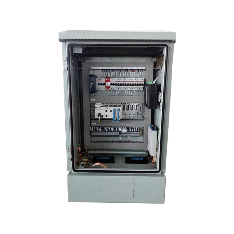
Outdoor Signal Control Cabinet
4. Performance Advantages Compared with Ordinary Industrial Cabinets
A standard industrial cabinet may provide a strong housing for equipment, but railway trackside service introduces requirements that go beyond general factory automation. The most important difference is the combination of environmental exposure, long cable runs, traction-related interference, lightning risk, operational safety, and demanding maintenance expectations.
| Performance area | Railway-oriented outdoor signal cabinet | Ordinary industrial cabinet |
|---|---|---|
| Primary application | Trackside signaling, subway control, railway communication, and outdoor transit systems | Factory automation, machinery, building services, and general electrical control |
| Environmental protection | IP55 enclosure concept with options for outdoor railway conditions | Protection level varies and may be intended mainly for indoor or sheltered locations |
| Material options | Galvanized steel or stainless steel according to corrosion and lifecycle requirements | Often based on a limited material range selected for general industrial use |
| EMC design | Shielding, filtered entry, surge protection, grounding separation, and isolated interfaces can be integrated | EMC measures may be limited to basic component-level protection |
| Traction interference consideration | Designed with awareness of high-current traction return paths and magnetic coupling | Usually not optimized for railway traction environments |
| Lightning protection | Coordinated SPD arrangements can be specified for power and signal lines | Protection may be added separately and may not be coordinated across interfaces |
| Field maintenance | Internal layout, cable management, grounding, and access can be customized for railway service | Layout is often optimized for general industrial equipment rather than trackside maintenance |
| Customization | Supports project-specific dimensions, mounting plates, compartments, cable entry, and interfaces | Typically supplied as a standard enclosure with limited adaptation |
The advantage of a railway-oriented cabinet is therefore systemic. The enclosure, internal mounting structure, access arrangement, electrical interfaces, and protective measures are developed around the conditions of railway service. This reduces the risk that individual components will be reliable while the cabinet assembly remains vulnerable to interference, moisture, poor grounding, or difficult maintenance.
4.1 Improved Operational Stability
Reliable signal equipment must remain stable during traction switching, power disturbances, and nearby lightning activity. A cabinet that combines shielding, filtering, grounding, and isolation can reduce the number of disturbance paths entering the control system. This supports more consistent operation and reduces nuisance alarms, communication resets, and intermittent faults.
Improved stability also benefits railway operators financially. Intermittent EMC faults can be difficult to diagnose because the equipment may operate normally during inspection. Reducing the number of unexplained events can lower troubleshooting time, service disruption, emergency dispatches, and replacement costs.
4.2 Better Protection of High-Value Electronics
Modern railway cabinets may contain network switches, industrial computers, PLCs, fiber communication equipment, relay modules, power supplies, and monitoring devices. These components can be expensive and may have long procurement lead times. A correctly designed enclosure helps protect them from dust, moisture, impact, and electrical transients.
The cabinet also provides a controlled mounting environment. Equipment can be fixed securely, cables can be supported, and heat-producing devices can be separated from temperature-sensitive components. This can extend service life and make the condition of the equipment easier to inspect.
4.3 Simplified Maintenance
Trackside maintenance is often performed under time pressure and difficult weather conditions. A well-organized cabinet should give technicians clear access to terminal blocks, protective devices, grounding points, and replaceable modules. Labels, wiring ducts, removable mounting plates, and logical circuit separation can reduce the time required for testing and repair.
Doors, locks, hinges, lifting points, and internal clearances must be considered from a practical maintenance perspective. A cabinet that is technically strong but difficult to open, inspect, or reconfigure can create avoidable lifecycle costs. Customer-specific access arrangements and internal layouts can help align the cabinet with the operator’s maintenance procedures.
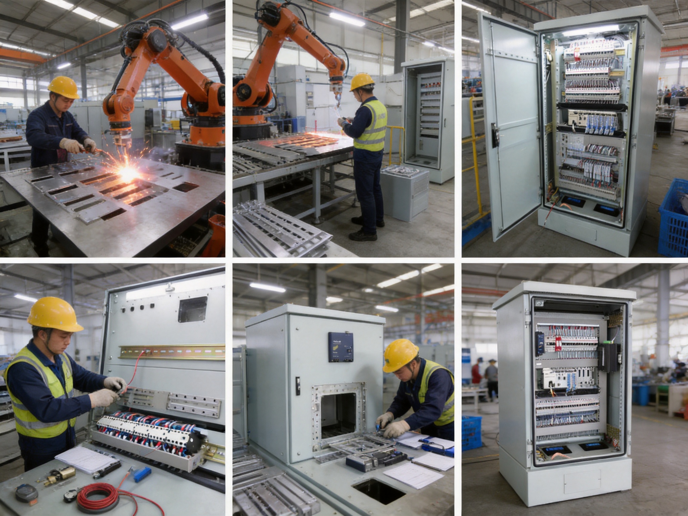
5. Advanced Manufacturing Process
The performance of an outdoor signal control cabinet depends heavily on manufacturing discipline. A cabinet may have a strong specification on paper, but inconsistent welding, poor surface preparation, inaccurate drilling, weak door bonding, or inadequate inspection can compromise the final product. A controlled manufacturing process is therefore essential.
5.1 Engineering Review and Project Specification
Manufacturing begins with a review of the application rather than only the external dimensions. Engineers should identify the installation environment, equipment list, heat dissipation requirements, cable entry direction, grounding method, door access, transport conditions, and maintenance clearance.
For railway projects, the review should also consider power supply characteristics, signal interface types, surge exposure, electromagnetic environment, separation between circuits, and applicable customer or railway standards. This early evaluation helps prevent late modifications that can affect cost, delivery, or cabinet performance.
Three-dimensional modeling and detailed production drawings can be used to verify mounting clearances, door swing, component placement, cable routing, and service access. When a cabinet is part of a larger system, interface drawings can confirm the relationship between the enclosure, foundation, cable trench, external conduits, and adjacent equipment.
5.2 Precision Sheet Metal Fabrication
Cabinet panels, doors, roofs, base sections, mounting plates, and internal partitions are produced through controlled sheet metal operations. Cutting and forming accuracy affects door alignment, gasket compression, panel fit, and the final appearance of the cabinet.
Computer-controlled cutting and bending equipment can improve repeatability across production batches. Accurate bends reduce unnecessary stress and help maintain consistent dimensions. Mounting holes and cable openings should be positioned according to approved drawings to ensure that equipment and accessories fit without field modification.
For customized railway cabinets, precision is particularly important because the internal equipment may be densely arranged. A small dimensional error in a mounting plate or partition can interfere with wiring ducts, circuit breakers, or cable entry hardware. Controlled fabrication reduces these risks and improves assembly efficiency.
5.3 Welding and Structural Assembly
Welded joints provide the mechanical strength required for lifting, transport, installation, and long-term outdoor service. Welding procedures should be selected according to the material and structural design. Weld quality affects not only strength but also sealing, corrosion resistance, appearance, and electrical continuity.
After welding, surfaces should be checked for distortion, sharp edges, incomplete joints, spatter, and areas that may interfere with doors or gaskets. Particular attention should be given to cabinet corners, base frames, door frames, lifting points, and grounding studs. A robust structure helps maintain alignment during temperature changes and mechanical vibration.
5.4 Surface Preparation and Coating
Surface preparation is a critical stage in corrosion protection. Oil, dust, oxidation, and manufacturing residue must be removed before coating. The selected pretreatment should be compatible with galvanized steel or stainless steel and with the final coating system.
Powder coating can provide a durable and uniform finish when the process is properly controlled. Key process variables include powder selection, application voltage, curing temperature, curing time, film thickness, and environmental cleanliness. The finished surface should be inspected for color consistency, pinholes, bubbles, poor adhesion, scratches, and exposed metal.
Where stainless steel is selected, the finishing process may include cleaning, polishing, passivation, or other treatments appropriate to the service environment. Fasteners and accessories should be selected to reduce galvanic corrosion between dissimilar metals.
5.5 Gasket, Door, and Locking Assembly
Doors are a major part of outdoor protection and EMC performance. Gaskets must be continuous, correctly positioned, and compressed evenly when the door is closed. A damaged or poorly fitted gasket can allow water and dust to enter and may also create an electromagnetic leakage point.
Hinges should support the door without excessive sagging. Locks should provide secure closure while allowing authorized maintenance personnel to gain access. Multi-point locking may be used for larger doors to achieve uniform compression around the perimeter.
Conductive bonding components can be installed where EMC requirements demand continuous electrical contact between the door and the cabinet frame. Bonding straps may also be used to maintain continuity across painted or mechanically movable sections.
5.6 Internal Mounting and Wiring Organization
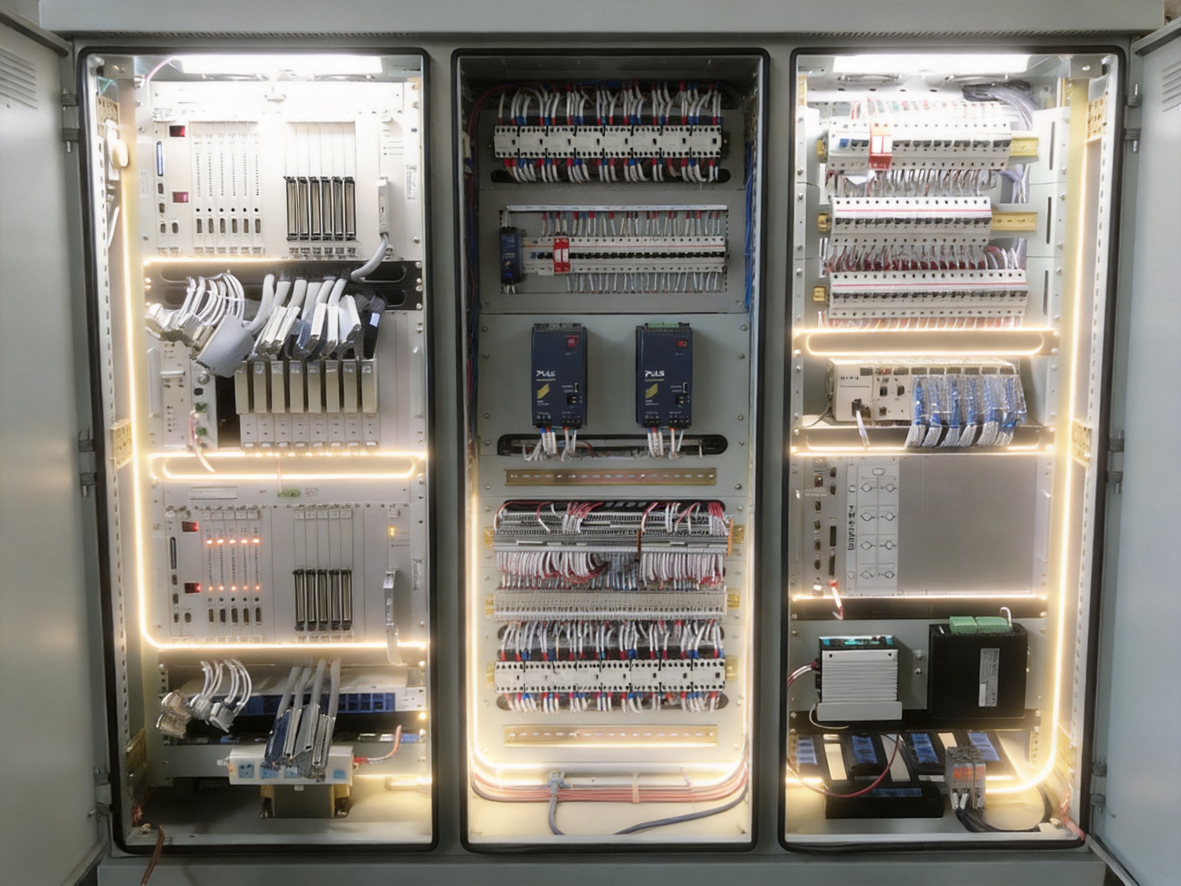
The internal structure can include galvanized mounting plates, DIN rails, cable ducts, terminal supports, partitions, grounding bars, and equipment brackets. The arrangement should support separation between power, control, communication, and field wiring.
Good wiring organization improves both safety and fault diagnosis. Cable routes should avoid sharp edges, excessive bending, heat sources, and unnecessary loops. Signal cables should be routed away from high-current conductors wherever possible. Shield termination points should be clearly defined, and spare capacity should be considered for future expansion.
Removable mounting plates can simplify assembly and field servicing. They allow equipment to be prewired or tested before final installation and can reduce the time technicians spend working inside a narrow enclosure. The exact configuration can be adjusted according to the customer’s bill of materials and maintenance strategy.
5.7 Inspection and Functional Verification
Quality control should be applied throughout production rather than only at the final stage. Incoming materials can be checked for specification, thickness, coating, and surface condition. In-process inspections can verify dimensions, welds, mounting holes, door alignment, and grounding points.
Final inspection may include dimensional verification, visual inspection, coating checks, gasket examination, lock operation, continuity testing, insulation checks, and accessory verification. When the cabinet is supplied with installed electrical components, additional tests may include wiring continuity, terminal identification, protective device arrangement, and functional simulation.
Inspection records provide traceability and help ensure consistency across repeated orders. For customized products, approved drawings and inspection checklists are especially valuable because they establish a clear reference for both the manufacturer and the customer.
6. Design Features That Support Long-Term Outdoor Service
6.1 Rain and Condensation Management
Keeping liquid water out of the cabinet is only one part of outdoor environmental control. Temperature changes can cause internal condensation even when the enclosure remains sealed. Condensation may occur when warm, humid air enters the cabinet and cools against internal surfaces.
Depending on the climate and equipment requirements, the cabinet may be fitted with anti-condensation heaters, thermostats, humidity control, ventilation systems, or pressure compensation devices. A roof overhang or rain canopy can reduce direct water exposure and solar heating. The cabinet foundation should also prevent water from accumulating around the base.
6.2 Heat Dissipation
Electronic equipment generates heat during operation. If heat accumulates inside the cabinet, component temperature may exceed the recommended range and reduce service life. Thermal management should consider internal power dissipation, ambient temperature, solar radiation, cabinet orientation, ventilation, and available installation space.
Natural convection may be sufficient for low-power equipment. Higher heat loads may require filtered fans, heat exchangers, air conditioners, or external cooling arrangements. Ventilation openings must be compatible with the required IP protection level and must not create unacceptable EMC leakage.
6.3 Mechanical Strength and Vibration Resistance
Railway environments can transmit vibration through the ground, foundation, and cable connections. The cabinet should have sufficient structural rigidity, stable mounting points, and secure internal component fixation. Heavy equipment should be positioned to avoid excessive stress on doors, mounting plates, and cable glands.
Fasteners should be tightened according to appropriate procedures, and components should be protected against loosening where necessary. Cable supports can prevent vibration from transferring mechanical stress to terminal connections. The base structure should be compatible with the project foundation and anchoring method.
6.4 Security and Access Control
Outdoor signaling equipment must be protected from unauthorized access and accidental interference. Lockable doors, controlled key systems, tamper-resistant fasteners, and door monitoring contacts can be specified where required.
Security features should not prevent emergency maintenance. The access system should align with railway operator procedures and allow authorized personnel to identify whether a cabinet has been opened. Internal barriers can prevent accidental contact with live power sections while allowing safe access to low-voltage control and communication equipment.
7. Customization for Railway Transit Projects
Railway projects rarely use a completely universal cabinet. The available space, equipment list, cable routes, foundation design, electrical standards, and maintenance rules vary from one line to another. A cabinet supplier must therefore provide a structured customization process.
7.1 External Dimensions and Installation Method
External dimensions can be adapted to the available trackside area, service walkway, equipment room boundary, or concrete foundation. Single-door, double-door, side-by-side, back-to-back, and multi-bay configurations may be considered according to access requirements.
The base can include a plinth, cable chamber, lifting provisions, anchor holes, or removable sections. Cable entry may be arranged through the bottom, side, rear, or top, depending on the site layout. The design should maintain bending radius requirements and prevent cable congestion.
7.2 Internal Compartmentalization
Separate compartments can be used for AC power, DC power, signaling relays, communication equipment, and field terminals. This arrangement may improve safety, EMC performance, and maintenance clarity. Partitions can also limit the spread of heat or prevent technicians from contacting unrelated circuits.
The internal layout should reserve enough space for cable routing, ventilation, labeling, testing, and future expansion. Overfilling a cabinet may reduce cooling performance and make EMC control more difficult. A well-designed layout balances equipment density with safe serviceability.
7.3 Electrical and Communication Interfaces
The cabinet can be prepared for terminal blocks, circuit breakers, relays, PLC systems, optical network devices, Ethernet switches, fiber distribution modules, and remote monitoring equipment. Interface selection should account for the number of circuits, conductor size, isolation requirements, communication speed, and maintenance method.
Railway communication systems may use both copper and fiber connections. Fiber interfaces offer electrical isolation and are particularly useful where long distances or strong electromagnetic fields are involved. Copper interfaces may require shield termination, surge protection, isolation, and carefully controlled cable routing.
7.4 Documentation and Identification
Clear documentation is essential for installation and future maintenance. Depending on the project, the supply package may include general arrangement drawings, mounting drawings, wiring diagrams, terminal schedules, bills of materials, grounding diagrams, inspection records, and operation or maintenance instructions.
Internal labels should be durable and easy to read. Terminal markings, cable numbers, circuit identifiers, warning labels, and equipment references should correspond to the approved drawings. Consistent identification reduces the risk of wiring errors and helps maintenance teams locate circuits quickly.
8. Manufacturing Strength and Integrated Supply Capability
Wanma Technology Co., Ltd. was established in 1997 and specializes in communication cabinets, communication electronic equipment, and passive optical components. Its product range supports Ethernet networks, optical communication networks, central equipment rooms, high-speed railway systems, and urban rail transit applications.
The company’s experience across communication and infrastructure equipment supports an integrated approach to cabinet manufacturing. Railway cabinets increasingly need to accommodate both signaling hardware and communication equipment, including Ethernet switches, fiber modules, network distribution components, and remote monitoring interfaces. A supplier familiar with these technologies can better understand the relationship between enclosure design and network equipment protection.
The company develops, manufactures, and markets its own branded products while also providing customized integrated solutions. This combination gives customers access to standard manufacturing resources together with project-specific engineering support. Customization may cover cabinet dimensions, materials, internal structures, cable entry, equipment mounting, protective devices, and appearance.
A broad international customer base also provides experience with differing technical expectations, delivery conditions, documentation requirements, and project coordination practices. The company’s sales network covers more than 20 countries and regions, including the United States, Australia, the United Kingdom, Italy, South Africa, and Ghana.
For railway contractors, system integrators, network operators, and equipment distributors, an integrated supplier can simplify procurement. Instead of coordinating separate manufacturers for the cabinet body, internal mounting structure, communication interfaces, and accessories, customers can work with one organization for a more unified solution.
9. Quality, Delivery, and Lifecycle Value
The initial purchase price is only one part of the total cost of a railway cabinet. A lower-cost enclosure may create additional expenses through installation modification, repeated field faults, difficult maintenance, corrosion, water ingress, or incompatible internal layouts. A more thoroughly engineered cabinet can deliver better lifecycle value by reducing these risks.
9.1 Reduced Installation Work
Accurate mounting plates, preplanned cable entries, clearly identified terminals, and project-specific accessories can reduce field labor. When equipment and interfaces are prepared according to approved drawings, installers spend less time drilling, cutting, repositioning, or correcting wiring routes on site.
9.2 Lower Maintenance Burden
Reliable sealing and surface protection reduce the frequency of corrosion repairs and water-ingress investigations. Organized internal wiring allows technicians to identify faults more quickly. Replaceable SPDs, accessible grounding bars, and clear inspection points support preventive maintenance.
9.3 Support for Spare Parts and Expansion
Railway systems often remain in service for many years. A cabinet should allow the replacement of protective devices, power supplies, communication modules, and terminal components without requiring complete enclosure replacement. Spare space and modular internal mounting can also support future upgrades.
9.4 Consistent Delivery
Project schedules are often linked to civil works, cable installation, signaling commissioning, and operational testing. Delays in cabinet delivery can affect multiple downstream activities. A supplier with established manufacturing procedures, material coordination, assembly capability, and inspection processes is better positioned to support repeat orders and project deadlines.
10. Recommended Selection Criteria
When selecting an outdoor signal control cabinet, buyers should evaluate more than the external appearance and nominal protection rating. The following questions can help determine whether the cabinet is suitable for a railway environment.
Is the cabinet intended specifically for outdoor railway, subway, or transit installation?
Are galvanized steel and stainless steel options available for different corrosion conditions?
Does the complete assembly support the required IP protection level, including doors, cable entries, and accessories?
Can the design accommodate shielding, filtered power entry, surge protection, isolated interfaces, and controlled grounding?
Are power, signal, communication, and field circuits separated appropriately?
Can the internal layout be customized for the actual equipment list and cable requirements?
Are heat dissipation, condensation prevention, and solar exposure considered?
Can the supplier provide drawings, inspection records, labels, and other project documentation?
Does the manufacturer have experience with communication equipment, high-speed railways, and urban rail transit systems?
Is there sufficient access for testing, SPD replacement, grounding inspection, and future expansion?
11. Installation and Maintenance Recommendations
Even a well-manufactured cabinet requires correct installation. The foundation should be level, stable, and capable of supporting the cabinet under wind and service loads. The cabinet should be anchored according to the approved installation drawings, and cable routes should prevent mechanical stress on entry points.
All cable glands should be tightened and sealed. Unused openings should be closed with suitable blanking elements. Cable shields should be terminated according to the EMC design rather than left unconnected or connected at random points. The protective earth conductor should be bonded before energization.
After installation, technicians should inspect door compression, lock operation, grounding continuity, cable routing, warning labels, and internal clearances. Surge protection status indicators should be checked during scheduled maintenance. If an SPD indicates end of life, it should be replaced before the next period of high lightning risk.
In moderate lightning regions, Type 1 and Type 2 SPDs may require replacement at intervals determined by the manufacturer, local conditions, and inspection results. Areas with frequent lightning or a history of direct strikes require a more conservative maintenance strategy. Any SPD involved in a significant surge event should be evaluated immediately.
Maintenance personnel should also look for coating damage, corrosion, loose fasteners, deteriorated gaskets, blocked ventilation filters, condensation, and signs of water entry. Early corrective action is usually less disruptive than repairing a cabinet after internal equipment has been damaged.
12. Frequently Asked Questions
Q1. Can a standard industrial control cabinet be used beside railway tracks?
A standard cabinet may be physically installable, but it should not be selected automatically for railway signaling. Railway environments can involve higher electromagnetic exposure, long outdoor cable runs, traction return currents, and lightning-induced surges. A suitable solution should be evaluated against the applicable railway EMC, environmental, electrical safety, and installation requirements.
Q2. What materials are available for the outdoor signal control cabinet?
The main material options are galvanized steel and stainless steel. Galvanized steel is suitable for many general outdoor railway locations and offers a balance of strength, corrosion resistance, and cost. Stainless steel is more appropriate for highly corrosive, humid, coastal, or chemically aggressive environments.
Q3. What does IP55 mean for this cabinet?
IP55 indicates protection against dust that could interfere with equipment operation and protection against water jets from any direction. Actual performance depends on the complete installation, including door seals, cable glands, cable entry plates, ventilation components, and correct maintenance.
Q4. Why are shielding and grounding both necessary?
Shielding reduces the entry of radiated electromagnetic energy, while grounding provides controlled paths for protective, surge, and reference currents. Shielding without proper bonding may perform poorly, and grounding without a suitable enclosure and cable arrangement may allow interference to reach sensitive circuits.
Q5. Can the cabinet include communication equipment?
Yes. The cabinet can be configured for Ethernet switches, optical communication equipment, fiber distribution components, remote I/O, power supplies, terminal blocks, and related railway network devices. The internal layout should separate communication circuits from high-energy power and relay circuits where appropriate.
Q6. Can the internal layout be customized?
Customization can include mounting plates, DIN rails, partitions, cable ducts, grounding bars, terminal arrangements, equipment brackets, cable entries, ventilation, heaters, locks, and access configuration. The best layout is developed from the actual equipment list, wiring diagram, installation space, and maintenance requirements.
Q7. Is grounding the cabinet to the rail sufficient?
No. The rail may carry large traction return currents and may have a significant voltage difference from remote earth. The grounding design should be developed by qualified engineers and may require a dedicated earth system, controlled bonding, isolated interfaces, cable shielding, and coordination with the railway earthing and bonding plan.
Q8. How can condensation be controlled?
Condensation can be managed through proper sealing, anti-condensation heaters, thermostats, pressure compensation, ventilation, drainage design, and control of internal heat. The correct solution depends on the local climate, enclosure size, equipment heat load, and installation conditions.
Q9. How often should surge protection devices be replaced?
Replacement intervals depend on lightning frequency, surge exposure, device condition, manufacturer recommendations, and maintenance records. Status indicators should be checked during routine inspections. A device that shows an end-of-life indication or has experienced a significant surge should be replaced promptly.
Q10. What information should be provided for a customized quotation?
Useful information includes external dimensions, material preference, protection level, equipment list, electrical drawings, cable entry direction, internal mounting requirements, grounding method, thermal conditions, door arrangement, surface color, quantity, delivery location, and applicable standards. Photographs or site drawings can also help confirm installation constraints.
13. Conclusion
An outdoor railway signal control cabinet is a critical part of the signaling infrastructure. Its purpose is not simply to cover electrical equipment. It must provide environmental protection, mechanical stability, safe access, efficient cable organization, electromagnetic shielding, surge control, grounding continuity, and long-term maintainability.
The galvanized steel or stainless-steel construction, IP55 protection concept, RAL7035 gray finish, and customizable internal arrangement make this cabinet suitable for subway signal control systems and many other railway transit applications. Its key advantage over a basic industrial enclosure is the ability to integrate railway-specific EMC and environmental considerations into the complete cabinet design.
Shielding, filtering, coordinated surge protection, segmented grounding, and isolated interfaces work together to reduce the risk of false operations caused by traction current or lightning. Precision fabrication, controlled welding, disciplined coating, careful door assembly, and systematic inspection further support product reliability.
Wanma Technology Co., Ltd. combines experience in communication cabinets, electronic equipment, passive optical components, Ethernet networks, optical communication systems, high-speed railways, and urban rail transit. Its manufacturing and customization capabilities allow customers to develop cabinets that match project-specific equipment, installation, and maintenance requirements.
For railway contractors, transit operators, system integrators, and communication equipment suppliers, the right cabinet can improve installation efficiency, protect valuable electronics, simplify maintenance, and support stable operation throughout the service life of the railway system.
References
1. EN 50121-4, Railway Applications: Electromagnetic Compatibility of Signaling and Telecommunications Apparatus.
2. IEC 60529, Degrees of Protection Provided by Enclosures.
3. IEC 61643 Series, Low-Voltage Surge Protective Devices.
4. IEC 61000 Series, Electromagnetic Compatibility.
5. EN 50124 Series, Railway Applications: Insulation Coordination.
6. EN 50125 Series, Railway Applications: Environmental Conditions for Equipment.
7. IEC 62208, Empty Enclosures for Low-Voltage Switchgear and Controlgear Assemblies.
8. IEC 61439 Series, Low-Voltage Switchgear and Controlgear Assemblies.
9. Railway Signaling and Communication Equipment Installation and Maintenance Practices.
10. Outdoor Enclosure Corrosion Protection, Grounding, Shielding, and Surge Protection Engineering Principles.
Product: Outdoor Signal Control Cabinet
PREV:Outdoor Telecom Cabinet Engineering for Reliable Network Infrastructure
NEXT:Intelligent Medical Carts for Safer Bedside Nursing and Digital Hospital Workflows
NEXT:Intelligent Medical Carts for Safer Bedside Nursing and Digital Hospital Workflows
Interested in cooperation or have questions?
Related products
-
-
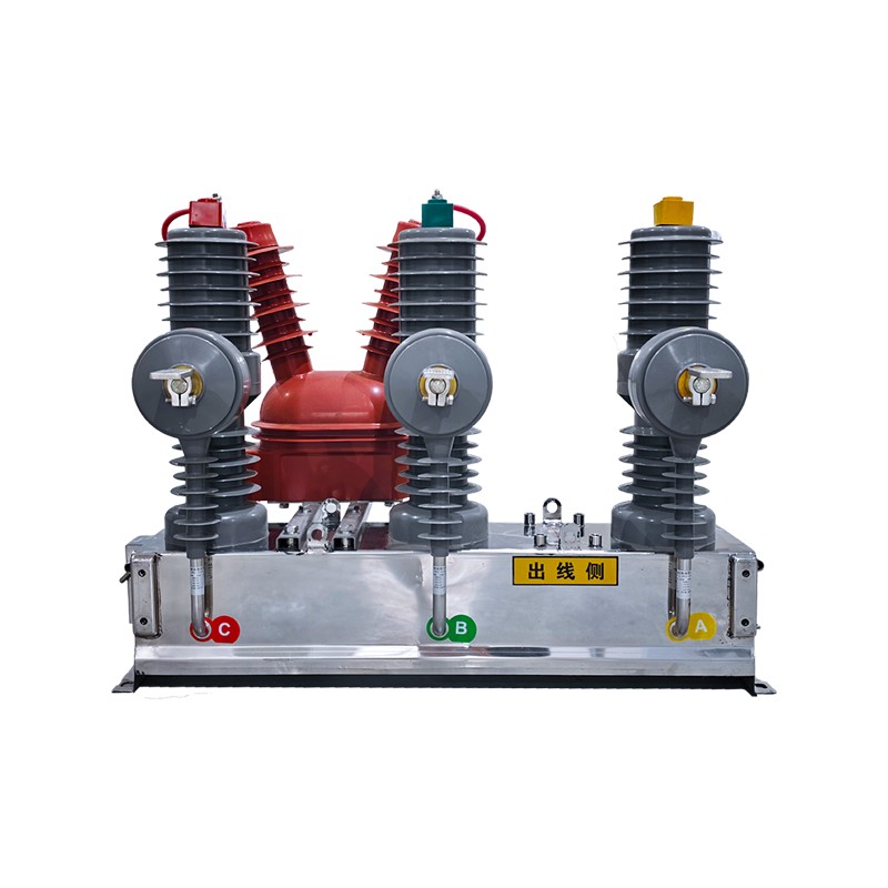
Product Overview: The ZW□-12/T630-25 outdoor high-voltage AC vacuum circuit breaker is a key device designed for 12 kV overhead distribution lines. By deeply integrating the primary switching unit wi...
See Details -
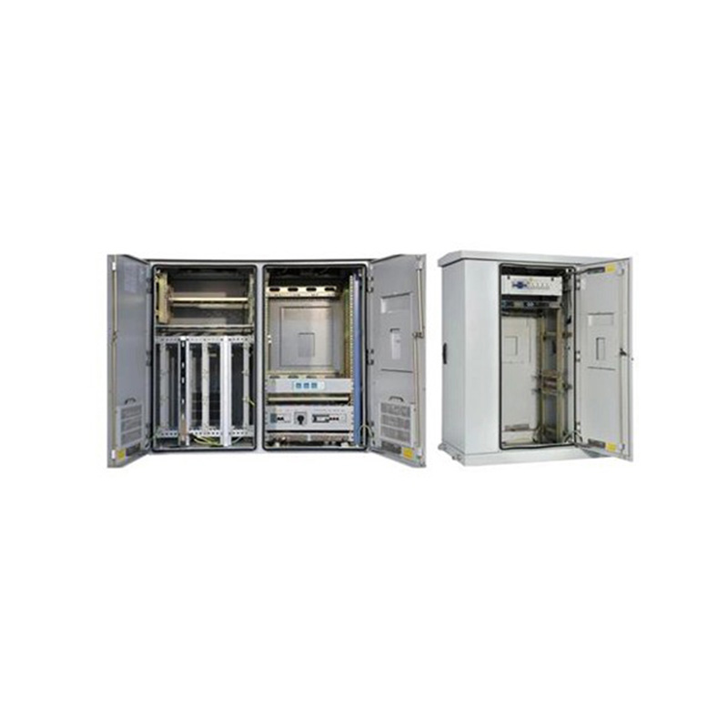
Application ScopeThis product is used in wireless network coverage systems, providing a safe and stable physical working environment and comprehensive security protection for workstations at wireless ...
See Details -
Application:It is used for the fixed network and broadband access, providing physical working environment and security system for the workstation in wired network. Features:•The cabinet is composed of...
See Details
Ready to Get started ? Contact Us Now !

Product.
Contact Details.
-
 +86 13958188250
-
 +86 13958188250
-
 [email protected]
-
 AUDIT Email:[email protected]
- Wanma Industrial Park Taihu Yuan Town Lin'an District Hangzhou City China.
QR Code

Copyright © Wanma Technology Co., Ltd. All Rights Reserved.
Privacy
Custom Ethernet Optical Network Railway Transit Equipments Suppliers
