

 English
 Français
 Español
 Português
 عربى






Feature: •Welded frame, stable structure with precise craftsmanship; •Single section, compatible with 19" standard equipments ; •Tempered glass front door with over 180 turning degree ; •Removable sid...
See DetailsWMSBG Single Section Wall Mount Cabinet: Compact, Durable, and Efficient Network Infrastructure
Content
- 1 Introduction
- 2 Product Positioning and Application Value
- 3 Main Construction and Functional Design
- 4 Material Selection and Manufacturing Process
- 5 Advantages Compared with Basic and Competing Cabinet Designs
- 6 Model Range and Selection Guidance
- 7 Installation and Cable Management Recommendations
- 8 Quality, Reliability, and Manufacturing Strengths
- 9 Optional Accessories and Customization
- 10 Recommended Use Cases
- 11 Technical Specification Summary
- 12 Q&A
- 12.1 Q1: What is the main purpose of the WMSBG single-section wall mount cabinet?
- 12.2 Q2: What is the difference between a single-section and double-section wall mount cabinet?
- 12.3 Q3: Can the cabinet accommodate equipment from different manufacturers?
- 12.4 Q4: Why are the mounting profiles adjustable?
- 12.5 Q5: Are the side panels removable?
- 12.6 Q6: Does the cabinet include ventilation?
- 12.7 Q7: What cable-entry options are provided?
- 12.8 Q8: What is the static loading capacity?
- 12.9 Q9: What colors are available?
- 12.10 Q10: What accessories can be added?
- 12.11 Q11: Is the cabinet suitable for outdoor installation?
- 12.12 Q12: How should the correct cabinet size be selected?
- 13 Conclusion
- 14 References
- 15 Product: WMSBG(Single Section Wall Mount Cabinet)
Introduction
Modern telecommunications and information technology systems require equipment enclosures that are secure, adaptable, easy to install, and efficient in the use of space. In many branch offices, small equipment rooms, retail locations, security control points, education facilities, and distributed communication sites, a full-size floor-standing rack is unnecessary. At the same time, ordinary wall boxes may not provide the mounting compatibility, cable access, structural strength, ventilation preparation, or maintenance convenience required by professional network equipment.
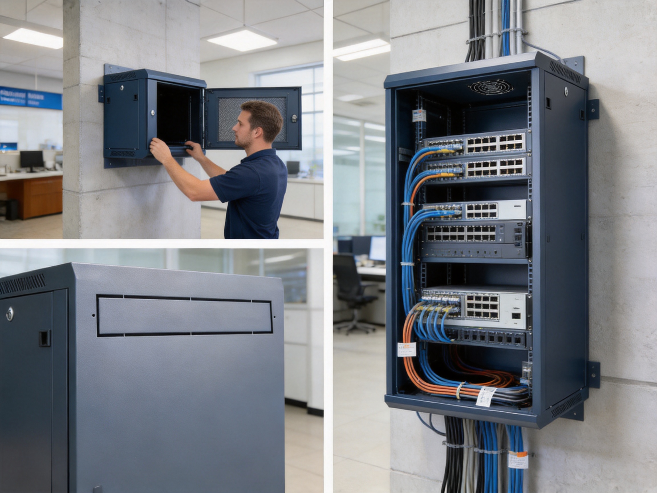
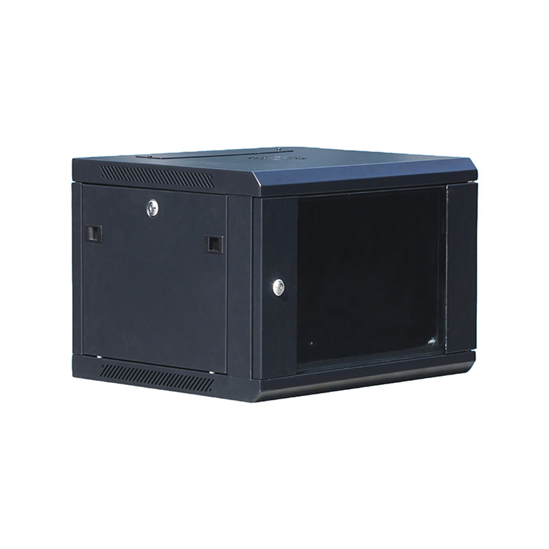
The WMSBG single section wall mount cabinet is designed to address this practical requirement. It provides a compact enclosure for 19-inch standard equipment while maintaining the essential characteristics expected from a professional telecommunications cabinet. Its welded frame, tempered glass front door, removable side panels, adjustable L-shaped mounting profiles, top and bottom cable entries, and wall-installation back panel create a balanced solution for network and communication deployments.
The cabinet is manufactured from SPCC quality cold-rolled steel and uses a multi-stage surface treatment process consisting of degreasing, pickling, phosphating, and powder coating. This combination supports structural stability, corrosion resistance, and a consistent external appearance. With a static loading capacity of up to 60 kg and an IP20 degree of protection, the product is suitable for indoor network and telecommunications applications where equipment needs to be organized, protected, and readily accessible.
Compared with basic wall-mounted boxes and some more complicated double-section designs, the single-section configuration offers a direct balance between cost, installation efficiency, equipment accessibility, and functional flexibility. It is particularly appropriate for compact networks that require professional 19-inch equipment accommodation without the size and expense of a larger cabinet system.
WMSBG(Single Section Wall Mount Cabinet)
Product Positioning and Application Value
A network cabinet is more than a metal enclosure. It provides the physical foundation for switches, patch panels, fiber optic equipment, routers, power distribution units, cable management components, and other communication devices. A suitable cabinet protects equipment from accidental contact, supports orderly cabling, simplifies maintenance, and helps create a consistent installation standard across multiple sites.
The WMSBG product family is positioned as a single-section wall mount cabinet for compact and medium-complexity installations. It is compatible with 19-inch standard equipment and is available in several heights and depths. The model range includes compact 4U and 6U versions, practical 9U and 12U versions, and larger 15U, 18U, 22U, and 27U options. Depths include 450 mm, 600 mm, and 800 mm configurations, allowing users to select a cabinet according to the dimensions of the equipment being installed.
This range gives installers greater flexibility than a single fixed-size enclosure. A small branch network may require only a switch, patch panel, and power accessory, while a larger distributed communication point may need additional rack space for fiber termination, cable management, wireless networking equipment, or security devices. Selecting the correct height reduces unused space while preserving room for future expansion.
The single-section structure is especially useful when the equipment and cable termination area do not need to be divided into separate compartments. Its direct internal layout allows installers to see and reach the main equipment without opening multiple cabinet sections. This can reduce installation time and simplify routine inspection.
Typical applications include Ethernet network distribution, optical communication systems, small server and edge computing installations, security monitoring systems, building automation, factory communication points, branch offices, retail networks, classrooms, small data rooms, railway auxiliary communication spaces, and telecommunications access locations.
Main Construction and Functional Design
Welded Frame for Structural Stability
The cabinet uses a welded frame rather than relying solely on a flat-pack structure. Welding creates a stable enclosure with consistent alignment between the main structural members. This is valuable when the cabinet must support rack-mounted equipment, maintain door alignment, and withstand repeated opening and closing during maintenance.
A stable frame also contributes to more accurate installation of the mounting profiles, side panels, top cover, and bottom panel. When these components remain properly aligned, equipment mounting becomes easier and the finished installation presents a more professional appearance.
For network cabinets, structural stability has a direct effect on long-term serviceability. Excessive movement or deformation can place stress on equipment mounting points, doors, locks, and cable connections. The WMSBG frame is therefore designed to provide a dependable foundation for equipment with a total static load of up to 60 kg, subject to correct wall anchoring and appropriate installation conditions.
Single-Section Layout
The single-section design creates one accessible equipment compartment. This configuration is simpler than a double-section cabinet, where the enclosure is divided into separate areas for equipment and cabling or for different types of systems.
A single compartment can offer several practical advantages. It requires fewer structural parts, occupies less wall space, and generally has a lower overall weight. The direct internal layout also makes it easier for installers to identify cable routes and reach mounted equipment. For a small or medium network, this simplicity often provides a better balance than a cabinet with additional internal separation.
Double-section cabinets remain valuable for high-density installations or projects requiring strict physical separation. However, where the installation does not require two compartments, the extra structure may increase cost, depth, and installation complexity. The WMSBG single-section cabinet is designed for users who want professional rack compatibility without unnecessary internal division.
Compatibility with 19-Inch Standard Equipment
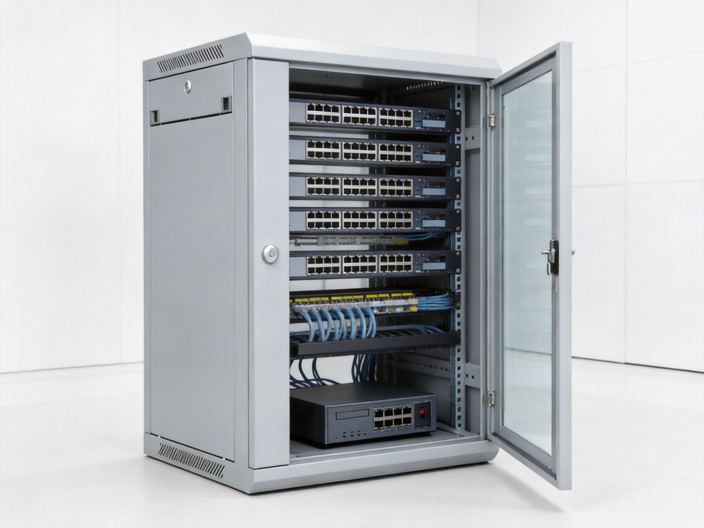
The cabinet is compatible with 19-inch standard equipment, one of the most important requirements for modern network infrastructure. This standard enables installers to use equipment from different manufacturers within the same enclosure, provided that the equipment meets the applicable rack-mount dimensions.
Common equipment that can be installed includes Ethernet switches, patch panels, fiber optic distribution units, cable organizers, rack-mounted power supplies, routers, security network equipment, wireless controllers, and other compact communication devices. Standard compatibility also simplifies replacement and future upgrading because users are not tied to a proprietary internal mounting format.
The cabinet includes L-shaped mounting profiles that can be adjusted along the mounting rail. This feature helps installers position the mounting profiles according to equipment depth and installation requirements. It can also make it easier to maintain a suitable clearance between the equipment, front door, rear cabling, and side panels.
Adjustable mounting profiles are particularly valuable when an installation includes equipment from multiple suppliers. Different devices may have different front-panel depths, rear connectors, power cable arrangements, and cable bend-radius requirements. Adjustable profiles allow the cabinet to be configured more precisely instead of forcing every installation into one fixed position.
Tempered Glass Front Door
The standard front door is made with tempered glass. Tempered glass provides visibility of the installed equipment while offering greater impact resistance than ordinary glass. Users can inspect indicator lights, patching arrangements, and equipment status without opening the cabinet.
The front door can turn through more than 180 degrees. This broad opening angle improves access in narrow corridors, rooms with adjacent walls, and installations where the cabinet is mounted close to other equipment. It also gives technicians more freedom when installing patch cords or servicing front-mounted devices.
Visibility and accessibility are important for distributed network installations. A technician may need to confirm switch activity, check link indicators, identify a patch panel, or verify that equipment is powered. A transparent door reduces the need for unnecessary opening and helps protect the internal equipment from accidental contact during routine visual checks.
The product information also identifies several front-door options, including a steel front door, a tempered glass front door, a tempered glass front door with a vented border, and a tempered glass front door with a meshed border. These variations allow the enclosure to be matched to different ventilation, visibility, and appearance requirements.
Removable Side Panels
Removable side panels provide a practical maintenance advantage. Once the cabinet is mounted on a wall, access through the front may not always be sufficient for cable routing, equipment installation, or inspection of internal fasteners. Removing the side panels gives technicians additional access to the interior.
The side panels are made from SPCC cold-rolled steel with a nominal thickness of 1.2 mm. They are designed to be removable for installation and maintenance, and a lock can be added as an option. Lockable side panels are useful where the user wants to restrict access to internal cabling or equipment while retaining the convenience of a removable panel.
Compared with fixed side walls, removable panels can reduce installation effort. They allow equipment and cable assemblies to be prepared more conveniently and can help technicians work in locations where the front door cannot be fully opened.
Top and Bottom Cable Entry
Cable entry points are provided on both the top cover and bottom panel. Each entry uses a knock-out plate, allowing the installer to select the most suitable routing direction. This arrangement supports installations where cables arrive from above, from a ceiling tray, from below, from a raised floor, or from a wall penetration.
Top and bottom access also helps separate incoming and outgoing cable paths according to the site layout. Ethernet cables, optical fiber cables, power connections, and patch cords can be routed more systematically when the cabinet offers more than one entry location.
For projects requiring improved cable protection or dust reduction, optional brush cable entries and other cable-entry designs are available. A brush entry can help close unused gaps around cables while maintaining smooth cable movement and reducing sharp contact with the enclosure.
Fan Cutout and Ventilation Preparation
A fan cutout is provided on the top cover to facilitate fan installation. Although many compact network devices can operate through natural convection, some equipment produces more heat, particularly when several active devices are installed together or when the cabinet is located in a warm environment.
The fan-ready top cover allows the enclosure to be adapted to the thermal requirements of the application. An installer can add a suitable fan assembly when required rather than purchasing a completely different cabinet. This provides a useful balance between standard configuration and future customization.
Ventilation options should always be selected according to the heat output of the installed equipment, ambient temperature, cabinet position, and manufacturer requirements. The fan cutout is a preparation feature; the final ventilation solution should be engineered for the specific installation.
Installing Back Panel for Wall Mounting
The installing back panel is designed to simplify wall fixation. It provides a dedicated interface between the cabinet and the building structure and can make positioning easier before the main cabinet body is secured.
A dedicated back panel is especially useful during installation because the installer can first establish the fixing points, confirm the cabinet height, and verify alignment. Correct wall anchoring is essential because the cabinet’s stated 60 kg static loading capacity depends on the suitability of the wall, anchors, fasteners, and installation method.
Concrete, brick, metal framing, and other wall structures may require different mounting hardware. The cabinet should be installed by qualified personnel who can evaluate the wall material and select suitable anchors. The mounting surface should be level and capable of supporting the cabinet, its equipment, and the relevant safety margin.
Material Selection and Manufacturing Process
SPCC Cold-Rolled Steel
The principal cabinet material is SPCC quality cold-rolled steel. Cold-rolled steel is widely used in professional enclosures because it offers a consistent surface, reliable formability, and suitable mechanical strength for cabinet panels and structural components.
Material thickness is selected according to the function of each component. The mounting profiles use 1.5 mm steel, while the other main cabinet components generally use 1.2 mm steel. The thicker mounting profiles provide additional support at the equipment interface, where rack-mounted devices transfer their load to the cabinet structure.
The use of different thicknesses is an efficient engineering approach. It places additional material where strength and mounting stability are most important while avoiding unnecessary weight in panels that do not require the same load-bearing performance. This helps the product remain suitable for wall mounting without compromising its core structural requirements.
Precision-Oriented Fabrication
Manufacturing a professional network cabinet requires accurate control of sheet-metal dimensions, hole positions, bends, welds, and assembly interfaces. The fabrication sequence typically includes material preparation, sheet-metal cutting, forming, punching or drilling, welding, surface treatment, coating, assembly, and inspection.
Accurate cutting and forming help ensure that panels fit correctly and that mounting profiles remain aligned. Consistent hole positioning is necessary for 19-inch equipment compatibility and for the installation of cage nuts, screws, shelves, cable organizers, and accessories.
Welding must be controlled to create a strong frame without producing excessive distortion. A stable welded frame supports reliable door operation and reduces the risk of misalignment during final assembly. After welding, components can be inspected for dimensional accuracy, sharp edges, surface defects, and correct interface relationships.
The product’s stated emphasis on stable structure and precise craftsmanship reflects the importance of process control at every stage. Cabinet quality is not determined by steel thickness alone. It also depends on how accurately the individual parts are produced and how consistently the final assembly is completed.
Multi-Stage Surface Treatment
The surface finish consists of degreasing, pickling, phosphating, and powder coating. Each stage serves a specific purpose.
Degreasing removes oil, grease, and contaminants left from steel processing. A clean surface is necessary for effective chemical treatment and coating adhesion.
Pickling helps remove oxidation, scale, and other surface impurities. This prepares the steel for the next treatment stage and creates a more uniform substrate.
Phosphating improves the surface condition for powder coating and supports corrosion resistance. It provides a conversion layer that helps the coating adhere to the metal surface.
Powder coating creates the final protective and decorative finish. Unlike a simple untreated or lightly painted enclosure, a properly prepared powder-coated surface can provide improved resistance to ordinary handling, abrasion, and indoor environmental exposure.
The standard color options include RAL 9004 and RAL 7035, with other colors available by request. RAL 9004 provides a deep black appearance, while RAL 7035 provides a light gray appearance commonly associated with network and electrical enclosures. Custom color selection can help users coordinate cabinets with corporate facilities, equipment rooms, or project standards.
Component-Level Manufacturing
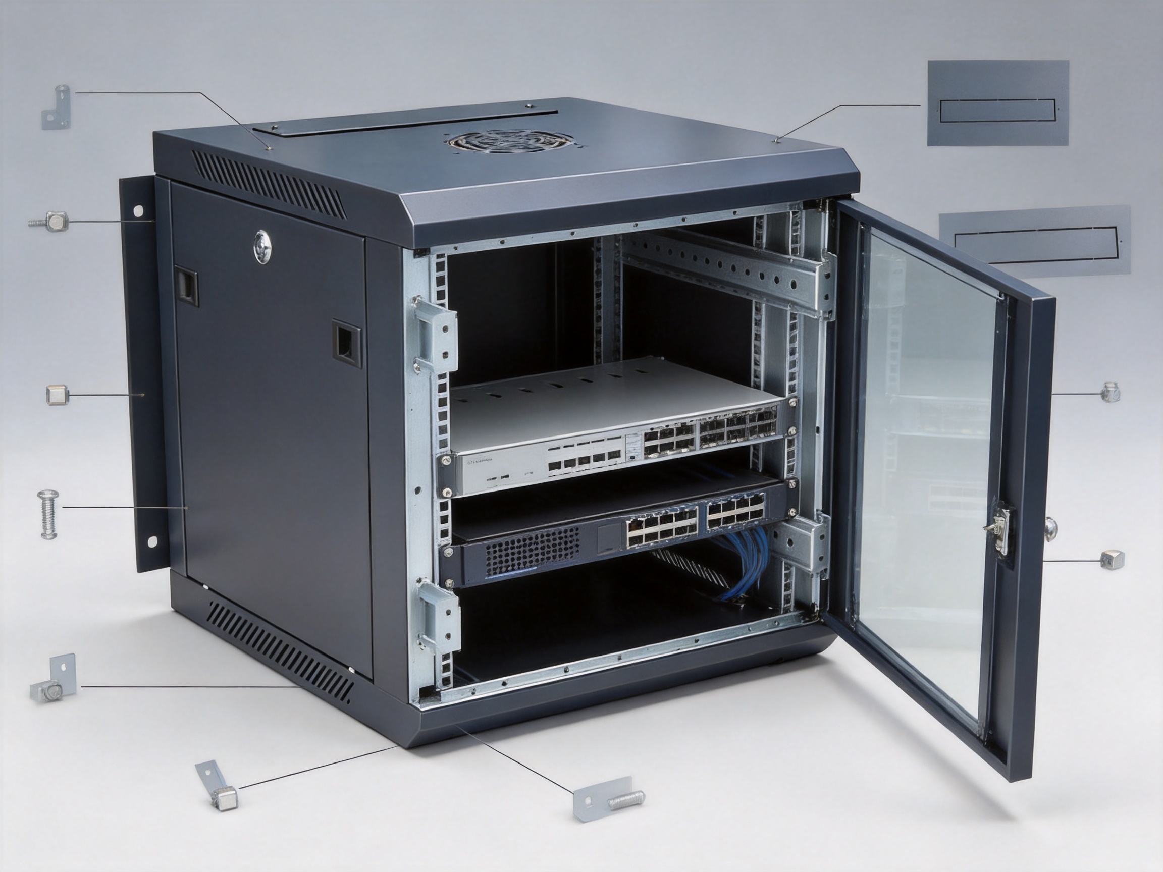
The cabinet is composed of multiple engineered parts rather than a single folded shell. The main components include the top cover, bottom panel, frame, mounting profiles, side panels, front door, lock, cable entry plates, and installing back panel.
The component structure supports modular production and configuration. For example, the same basic cabinet platform can accommodate different front-door types, optional locks, fixed shelves, decorative strips, and cable-entry arrangements. This approach allows the manufacturer to provide a standard product while still responding to project-specific requirements.
The product information identifies the main component materials and quantities. The top cover, bottom panel, frame, side panels, cable entry plates, and installing back panel use SPCC cold-rolled steel. The mounting profiles use thicker SPCC steel. The front door uses 5 mm tempered glass, while the lock is made from galvanized material and the supplied M6 screws and square nuts are steel with color zinc coating.
| Component | Quantity | Material or Specification | Finish or Treatment |
|---|---|---|---|
| Top cover | 1 piece | SPCC cold-rolled steel, 1.2 mm | Powder coated |
| Bottom panel | 1 piece | SPCC cold-rolled steel, 1.2 mm | Powder coated |
| Frame | 2 pieces | SPCC cold-rolled steel, 1.2 mm | Powder coated |
| Mounting profile | 4 pieces | SPCC cold-rolled steel, 1.5 mm | Powder coated |
| Side panel | 2 pieces | SPCC cold-rolled steel, 1.2 mm | Powder coated |
| Front door | 1 piece | 5 mm tempered glass | Powder-coated metal frame |
| Lock | 1 piece | Galvanized material | Protective finish |
| Cable entry plate | 2 pieces | SPCC cold-rolled steel, 1.2 mm | Powder coated |
| Installing back panel | 1 piece | SPCC cold-rolled steel, 1.2 mm | Powder coated |
Advantages Compared with Basic and Competing Cabinet Designs
More Professional Than Basic Wall Boxes
Basic wall boxes may provide a low-cost enclosure, but they often lack standard 19-inch mounting, adjustable profiles, removable side panels, a glass viewing door, or structured cable-entry options. These limitations can increase installation time and make future maintenance more difficult.
The WMSBG cabinet is designed around professional network equipment rather than general-purpose storage. Its mounting profiles, rack hardware, front-door options, and cable access points are intended for communication infrastructure. This makes it easier to create a consistent installation that can be inspected and serviced over its operating life.
Simpler and More Economical Than Double-Section Cabinets
Double-section cabinets are useful when cable termination and active equipment must be separated physically. However, they normally contain more parts, require more internal space, and may involve more complicated installation and maintenance procedures.
For a small network, the additional compartment may not provide enough value to justify the extra cost. The single-section WMSBG design offers a simpler internal layout and a more direct path between equipment and cables. It is therefore well suited to branch networks, small communication rooms, and distributed access points where a compact footprint is more important than compartmental separation.
Better Maintenance Access
Maintenance access is a major differentiator between a well-designed cabinet and a basic enclosure. The WMSBG front door opens beyond 180 degrees, and the side panels can be removed. These features provide several access directions for installation and service.
A technician can open the front door to work on patch panels and front-mounted devices, remove a side panel to reach internal fasteners or cable routes, and use the top or bottom entry plates to manage incoming cables. This reduces the need to remove the entire cabinet from the wall or disturb unrelated equipment during service.
Flexible Configuration
The cabinet supports optional accessories such as fixed shelves, lockable side panels, different front-door styles, decorative strips, brush cable entries, and other design variations. This level of configuration is an advantage over rigid enclosures that can only be used in their original configuration.
Configuration flexibility can reduce the need for custom cabinet fabrication. Users can select a standard model and add only the features required for a particular project. This can improve purchasing efficiency while still supporting different installation environments.
Balanced Strength and Weight
The 1.5 mm mounting profiles and welded frame provide a stable equipment-supporting structure, while 1.2 mm panels help control overall weight. This balance is important for wall-mounted products. An enclosure must be strong enough for the equipment load but not unnecessarily heavy for transportation and installation.
The stated static loading capacity is 60 kg. This capacity makes the cabinet suitable for many compact network assemblies, although the actual permissible load must always be considered together with wall strength, anchor selection, load distribution, and the weight of accessories.
Improved Visual Inspection
The tempered glass front door allows users to monitor equipment without opening the cabinet. This is useful in locations where technicians need to check link indicators, power status, and equipment arrangement during routine inspections.
Visual access can also help reduce unnecessary handling. Every additional cabinet opening creates an opportunity for dust entry, cable disturbance, or accidental contact. A transparent door supports quick checks while preserving the physical barrier around the equipment.
Model Range and Selection Guidance
The WMSBG model range is identified by cabinet width, depth, and capacity. The product family includes 600 × 450 mm, 600 × 600 mm, and 600 × 800 mm width-and-depth configurations. Capacities range from 4U to 27U, depending on the model.
| Model Group | Capacity Range | Width × Depth | Typical Selection Consideration |
|---|---|---|---|
| WMSBG-6404 to WMSBG-6427 | 4U to 27U | 600 × 450 mm | Compact equipment and limited wall depth |
| WMSBG-6604 to WMSBG-6627 | 4U to 27U | 600 × 600 mm | Equipment requiring additional internal depth |
| WMSBG-6815 | 15U | 600 × 800 mm | Deeper equipment and expanded cable clearance |
| WMSBG-6818 | 18U | 600 × 800 mm | Deeper equipment with additional rack capacity |
The 450 mm depth models are appropriate when the installed devices are relatively shallow and wall space is limited. They can be useful for compact switches, patch panels, fiber equipment, and other devices that do not require substantial rear clearance.
The 600 mm depth models provide additional room for deeper equipment, cable bend radius, power connections, and future expansion. They may be preferable when the installer wants more flexibility in arranging equipment and managing cables.
The 800 mm depth models offer the greatest internal depth in the listed range. They are suitable for deeper equipment and installations that require more generous rear clearance. Before selecting an 800 mm model, the installer should confirm that the supporting wall and surrounding area can accommodate the cabinet dimensions and load.
Capacity should be selected with expansion space in mind. A cabinet that is completely filled at the time of installation may become difficult to maintain or expand. Leaving spare rack units can provide room for future equipment, cable organizers, ventilation accessories, and replacement devices.
Installation and Cable Management Recommendations
Planning the Installation Location
The cabinet should be installed in a clean, dry indoor location with sufficient space for the front door to open and for technicians to perform service work. The installer should also consider the cable approach, ventilation, power availability, wall construction, and access for future maintenance.
Although the front door opens more than 180 degrees, nearby walls, furniture, pipes, and other cabinets may still restrict access. A clear working area in front of the cabinet improves safety and reduces the chance of damaging patch cords or equipment during maintenance.
Checking Wall Capacity
The 60 kg static loading capacity refers to the cabinet’s structural capability under appropriate conditions. The wall and mounting hardware must be able to support the cabinet and its installed equipment. A strong cabinet cannot compensate for an unsuitable wall or incorrectly selected anchors.
Before installation, the mounting surface should be checked for flatness and strength. The back panel should be aligned correctly, and all fixing points should be secured using hardware appropriate for the wall material. The cabinet should not be installed on a damaged or unstable surface.
Arranging Rack Equipment
Heavy equipment should generally be mounted in lower rack positions to reduce the center of gravity and improve overall stability. Frequently accessed patch panels and cable management components can be placed where they are easiest to reach. Equipment should be installed with adequate clearance for ventilation and connector access.
Rack screws and square nuts should be installed carefully to avoid cross-threading or damage to the mounting holes. The supplied M6 B-head screws and M6 square nuts provide a standard fastening method for compatible equipment and accessories.
Routing Cables
Top and bottom cable entry plates allow the installer to choose a route that matches the building infrastructure. Cables should be routed with adequate bend radius, particularly optical fiber cables and high-performance copper cables. Excessive bending can increase transmission loss or degrade long-term reliability.
Cables should be supported so that their weight does not pull on equipment ports or patch panel connectors. Service loops may be included where appropriate, but excessive unused cable should not obstruct ventilation or prevent the side panels from being refitted.
Where cables pass through metal openings, suitable protective measures should be used. Optional brush cable-entry designs can improve cable organization and help close the opening around cable bundles. Cable labels should be applied consistently so that technicians can identify connections without unnecessary interruption of service.
Ventilation and Thermal Management
Equipment heat output should be considered before the cabinet is populated. Devices should not be installed in a way that blocks their air inlets or outlets. If the equipment load creates significant heat, the top-cover fan cutout can be used to install a compatible ventilation fan.
Ventilation design should consider airflow direction, fan capacity, dust conditions, ambient temperature, and the location of the cabinet. A fan may improve heat removal, but it also introduces a component that requires power and periodic maintenance. The appropriate solution depends on the equipment and operating environment.
Quality, Reliability, and Manufacturing Strengths
Long-Term Industry Experience
Wanma Technology Co., Ltd. was established in 1997 and specializes in communication cabinets, communication electronic equipment, and passive optical components. Its long operating history provides experience in developing products for network, telecommunications, optical communication, railway, and urban rail transit applications.
Communication infrastructure products must function reliably in systems where replacement can be disruptive and costly. Experience in these sectors supports a practical understanding of equipment integration, cabinet construction, cable routing, installation conditions, and project delivery requirements.
Integrated Product Capability
The company develops, manufactures, and markets its own branded products while also providing integrated solutions for customized products. This capability is valuable for customers who need more than an off-the-shelf enclosure.
Customization may involve cabinet dimensions, door styles, color, cable-entry arrangements, locking systems, shelves, accessories, or other project-specific details. By combining product manufacturing with solution development, the supplier can better coordinate the cabinet with the wider communication infrastructure.
Application Experience Across Network Environments
The company’s products are used in Ethernet networks, optical communication networks, central equipment rooms, national high-speed railways, and urban rail transit systems. These application areas require organized physical infrastructure and dependable equipment protection.
Railway and transit environments can place strict demands on equipment organization, installation consistency, maintenance access, and project coordination. Experience serving such environments can contribute to a disciplined approach to cabinet design and production, even when the WMSBG cabinet itself is selected for a smaller indoor network installation.
Manufacturing Consistency
Consistent manufacturing is essential when cabinets are deployed across multiple sites. Uniform dimensions, colors, mounting positions, door operation, and accessory compatibility make installation and maintenance more predictable.
The WMSBG design uses standardized components and material specifications. This helps support repeatable production and makes it easier for customers to order matching cabinets for different branches, buildings, or network expansion phases.
Supply and Partnership Support
Wanma Technology has a sales network covering more than 20 countries and regions, including the United States, Australia, the United Kingdom, Italy, South Africa, and Ghana. Its stated focus includes reliable product quality, timely delivery, and long-term strategic partnerships.
For infrastructure projects, supplier reliability includes more than product performance. It also involves communication, technical coordination, delivery planning, packaging, documentation, and after-sales support. These factors can influence the total project cost and installation schedule.
Optional Accessories and Customization
The WMSBG cabinet can be adapted through several optional features. Removable side panels may be equipped with locks when additional access control is required. Fixed shelves can support non-rack-mounted equipment, power supplies, or auxiliary devices, provided that the total load remains within the applicable limits.
Different front-door designs are available for projects that prioritize visibility, ventilation, or a more enclosed appearance. A fully glazed door supports visual inspection, while vented or meshed borders can help support airflow. The appropriate choice depends on equipment heat output and the desired appearance.
Decorative strips for the glass side or door area may be used when a particular visual finish is required. Brush cable entries and other cable-entry designs can improve cable organization and reduce exposed openings around cable bundles.
Color customization is also available beyond the normal RAL 9004 and RAL 7035 options. Custom colors can support project identification, interior design requirements, or corporate equipment standards. Color selection should be confirmed during the quotation and production stages because special colors may affect minimum order quantities and lead time.
Recommended Use Cases
Small Office and Branch Networks
Branch offices often need a compact enclosure for a network switch, patch panel, router, power accessory, and fiber termination equipment. The WMSBG cabinet keeps this equipment organized while avoiding the footprint of a floor-standing rack.
Retail and Commercial Facilities
Retail stores, restaurants, and commercial buildings may have limited technical space. A wall-mounted enclosure can be installed in a back office, service room, or communications area and can protect network equipment from accidental contact.
Optical Communication Access Points
Optical communication installations may require a combination of fiber distribution, Ethernet switching, patching, and cable management. The cabinet’s 19-inch compatibility and flexible cable-entry design can support these compact access points.
Security and Monitoring Systems
Video surveillance and access-control systems commonly use network switches, recorders, power equipment, and fiber converters. A lockable and visible cabinet can organize this equipment and help authorized personnel inspect operating status.
Industrial and Transportation Auxiliary Systems
In suitable indoor areas of industrial facilities, railway support buildings, and urban transit infrastructure, the cabinet can provide a compact housing solution for communication equipment. The installation must be evaluated according to the environmental requirements of the specific site.
Technical Specification Summary
| Specification | Product Information |
|---|---|
| Product type | Single-section wall mount network cabinet |
| Equipment compatibility | 19-inch standard equipment |
| Material | SPCC quality cold-rolled steel |
| Mounting profile thickness | 1.5 mm |
| Other primary component thickness | 1.2 mm |
| Front door | Tempered glass option, opening beyond 180 degrees |
| Side panels | Removable; lock optional |
| Cable entry | Top cover and bottom panel with knock-out plates |
| Ventilation preparation | Fan cutout on top cover |
| Static loading capacity | 60 kg |
| Degree of protection | IP20 |
| Surface finish | Degreasing, pickling, phosphating, powder coating |
| Standards referenced | ANSI/EIA RS-310-D, IEC 297-2, DIN 41497 Part 1, DIN 41494 Part 7, GB/T 3047.2-92 |
| Normal colors | RAL 9004 and RAL 7035 |
Q&A
Q1: What is the main purpose of the WMSBG single-section wall mount cabinet?
The cabinet is designed to house 19-inch standard network and telecommunications equipment in compact indoor installations. It provides equipment mounting, cable access, physical protection, visibility, and maintenance access in a wall-mounted format.
Q2: What is the difference between a single-section and double-section wall mount cabinet?
A single-section cabinet has one main internal equipment compartment, while a double-section cabinet divides the enclosure into two separate areas. The single-section version is generally simpler, more compact, and more economical. A double-section version may be preferable when equipment and cable termination must be physically separated.
Q3: Can the cabinet accommodate equipment from different manufacturers?
Yes. The cabinet is designed for 19-inch standard equipment, allowing compatible switches, patch panels, routers, fiber units, power accessories, and other rack-mounted devices from different manufacturers to be installed in the same enclosure.
Q4: Why are the mounting profiles adjustable?
Adjustable L-shaped mounting profiles allow the installer to position the equipment mounting points according to equipment depth, connector clearance, cable routing, and internal space requirements. This is useful when several equipment types are installed together.
Q5: Are the side panels removable?
Yes. The side panels are removable to make equipment installation, cable routing, and maintenance easier. A lock can be added as an optional feature when access control is required.
Q6: Does the cabinet include ventilation?
The top cover includes a fan cutout to facilitate the installation of a suitable fan. The need for active ventilation depends on the heat output of the installed equipment, the ambient conditions, and the cabinet location.
Q7: What cable-entry options are provided?
The standard design includes cable entries on the top cover and bottom panel using knock-out plates. Optional brush cable entries and other cable-entry designs can be selected for projects that require improved cable organization or gap coverage.
Q8: What is the static loading capacity?
The stated static loading capacity is 60 kg. The wall, anchors, fasteners, cabinet installation, and load distribution must all be suitable for the intended equipment weight. The cabinet should be installed by qualified personnel.
Q9: What colors are available?
The normal colors are RAL 9004 and RAL 7035. Other RAL colors may be available for customized projects, subject to confirmation with the manufacturer.
Q10: What accessories can be added?
Optional accessories include lockable side panels, fixed shelves, different front-door designs, decorative strips, brush cable entries, and other customized cable-entry or cabinet design features.
Q11: Is the cabinet suitable for outdoor installation?
The cabinet has an IP20 degree of protection and is intended primarily for indoor applications. Outdoor use or installation in harsh environments would require a separate evaluation of weather, dust, moisture, temperature, corrosion, and security requirements.
Q12: How should the correct cabinet size be selected?
The selection should consider equipment height in rack units, equipment depth, rear connector clearance, cable bend radius, ventilation space, accessory requirements, and future expansion. It is generally advisable to retain some spare rack capacity rather than filling the cabinet completely at the initial installation stage.
Conclusion
The WMSBG single section wall mount cabinet provides a practical and professional enclosure for compact network and telecommunications infrastructure. Its welded frame, SPCC cold-rolled steel construction, 19-inch equipment compatibility, adjustable L-shaped mounting profiles, tempered glass front door, removable side panels, flexible cable entry, fan-ready top cover, and installing back panel address the key requirements of modern wall-mounted equipment deployment.
Its principal advantage is balance. The cabinet is more capable and serviceable than a basic wall box, while remaining simpler and more economical than many double-section designs. It offers sufficient structural performance for a stated 60 kg static load, multiple model sizes, several depth choices, and optional accessories for different project requirements.
The manufacturing approach combines material selection, component-specific thickness, welded construction, controlled fabrication, and multi-stage surface treatment. These characteristics support a product that is designed not only for initial installation but also for long-term maintenance and organized network expansion.
Supported by Wanma Technology’s experience in communication cabinets, optical communication products, railway applications, and customized infrastructure solutions, the WMSBG product family is suitable for businesses and system integrators seeking dependable wall-mounted equipment storage. For small offices, branch networks, optical access points, security systems, and other compact indoor communication environments, it provides an efficient foundation for reliable physical network infrastructure.
References
1. ANSI/EIA RS-310-D, Racks, Panels, and Associated Equipment.
2. IEC 297-2, Dimensions of Mechanical Structures of the 482.6 mm Series.
3. DIN 41497 Part 1, Mechanical Structures for Electronic Equipment.
4. DIN 41494 Part 7, Mechanical Structures for Electronic Equipment.
5. GB/T 3047.2-92, Basic Dimensions of Panels, Racks, and Cabinets for Electronic Equipment.
6. Product technical information for the WMSBG single-section wall mount cabinet.
7. General engineering practices for 19-inch telecommunications cabinet installation and cable management.
8. General manufacturing principles for cold-rolled steel enclosures, phosphating, and powder-coated surface protection.
Product: WMSBG(Single Section Wall Mount Cabinet)
PREV:Liquid-Cooled Containerized Data Centers for High-Density Computing and Network Modernization
NEXT:Outdoor Telecom Cabinet Engineering for Reliable Network Infrastructure
NEXT:Outdoor Telecom Cabinet Engineering for Reliable Network Infrastructure
Interested in cooperation or have questions?
Related products
-
-
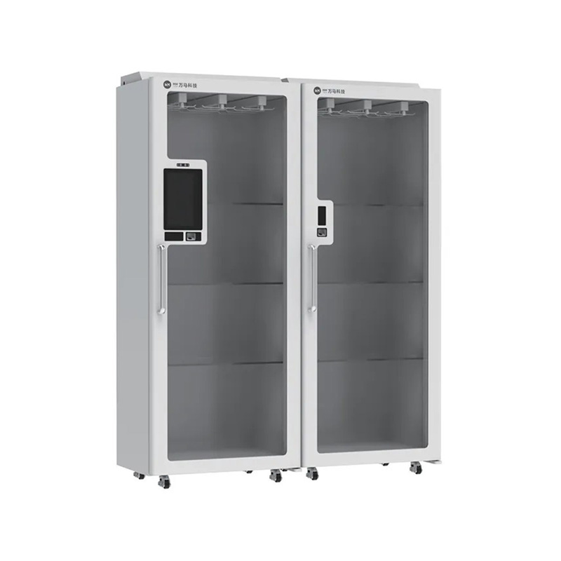
Product Definition The Single Door Consumables Elocker is an intelligent storage solution designed for secure consumables access and management, integrating identity authentication, accurate inventory...
See Details -
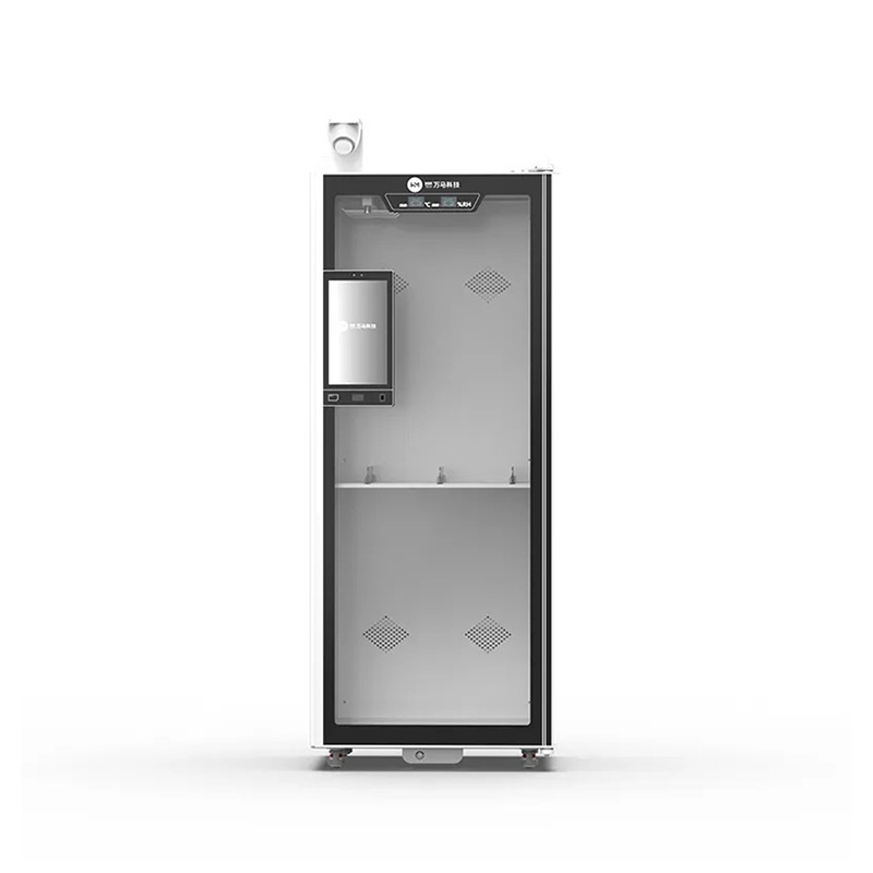
Product Definition This product is a high-capacity intelligent consumables management cabinet designed for hospitals, laboratories, and medical institutions, integrating RFID technology, smart access ...
See Details -
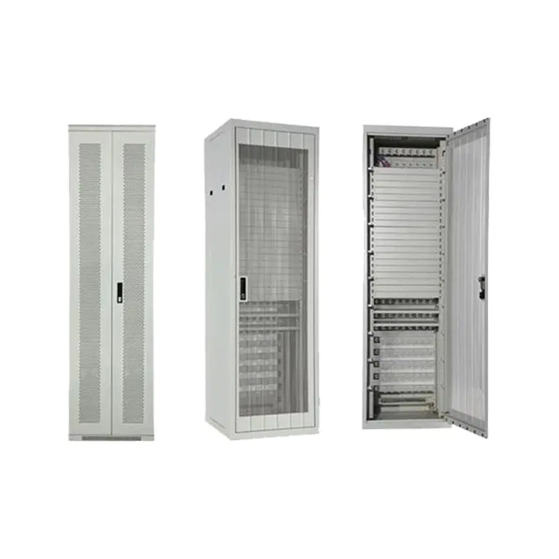
Application:It is used in generic cabling system for computer network and other projects and is mainly used to install the server, display, UPS and other 19-inch equipments and equipments in other siz...
See Details
Ready to Get started ? Contact Us Now !

Product.
Contact Details.
-
 +86 13958188250
-
 +86 13958188250
-
 [email protected]
-
 AUDIT Email:[email protected]
- Wanma Industrial Park Taihu Yuan Town Lin'an District Hangzhou City China.
QR Code

Copyright © Wanma Technology Co., Ltd. All Rights Reserved.
Privacy
Custom Ethernet Optical Network Railway Transit Equipments Suppliers
