

 English
 Français
 Español
 Português
 عربى







Application ScopeThe GPX129-09T fiber optic distribution frame is used to connect, distribute, and manage fiber optic cables and optical communication equipment. It is suitable for large-capacity fibe...
See DetailsHigh-Density 19-Inch Optical Distribution Frame for Reliable Fiber Network Management
Content
- 1 1. The Role of an Optical Distribution Frame in Modern Networks
- 2 2. Compact 1U Construction and Space Efficiency
- 3 3. Integrated Splicing and Distribution Functions
- 4 4. Materials and Structural Design
- 5 5. Drawer-Type Access for Installation and Maintenance
- 6 6. Cable Fixation and Fiber Protection
- 7 7. SC Adapter Interface and Optical Performance
- 8 8. Electrical and Insulation Characteristics
- 9 9. Compatibility with Different Cable Types
- 10 10. Accessory Package and Installation Readiness
- 11 11. Working Environment and Deployment Conditions
- 12 12. Manufacturing Strengths and Engineering Capability
- 13 13. Advantages Compared with Basic or Less Integrated Alternatives
- 14 14. Applications in Different Network Environments
- 15 15. Recommended Installation Practices
- 16 16. Maintenance and Service Considerations
- 17 17. Procurement and Project Selection Guidance
- 18 18. Quality, Delivery, and Partnership Value
- 19 19. Q&A
- 19.1 Q1: What is the capacity of the WM-ODF-24SC?
- 19.2 Q2: Can it be installed in a standard communication rack?
- 19.3 Q3: What connector type does the product use?
- 19.4 Q4: Does the unit support fiber splicing?
- 19.5 Q5: How does the drawer structure help technicians?
- 19.6 Q6: What cable types can be used with this ODF?
- 19.7 Q7: What are the specified optical performance values?
- 19.8 Q8: Which operating wavelengths are supported?
- 19.9 Q9: What materials are used in the construction?
- 19.10 Q10: What accessories are included?
- 19.11 Q11: Is the product suitable for railway and urban rail transit applications?
- 19.12 Q12: What should be considered when maintaining the unit?
- 19.13 Q13: Can the manufacturer provide customized solutions?
- 20 20. Conclusion
- 21 References
- 22 Product: WM-ODF-24SC 19inch ODF
Modern communication networks depend on organized, protected, and serviceable fiber infrastructure. As Ethernet, broadband access, railway communications, data centers, enterprise networks, and 5G transport systems continue to expand, network operators require more than simple fiber termination. They need a compact platform that can receive incoming optical cables, protect delicate fibers, accommodate splicing, provide orderly distribution, and support efficient maintenance throughout the service life of the network.
The WM-ODF-24SC 19-inch Optical Distribution Frame is designed to address these requirements in a compact 1U format. It combines fiber splicing and distribution functions in a single high-density unit with capacity for 24 optical cores. Its standard rack dimensions allow it to be installed in a 19-inch cabinet or distribution frame, while its drawer-type construction gives technicians access to the splice area without removing the entire unit from the rack.
Although the equipment occupies only one rack unit, it provides several functions normally associated with larger fiber management assemblies. These functions include cable entry and fixation, fiber routing, splice protection, pigtail organization, adapter termination, and controlled access for installation or maintenance. This integrated design helps reduce space consumption and simplifies the organization of fiber connections in communications rooms and equipment cabinets.
Manufactured by Wanma Technology Co., Ltd., a company with experience in communication cabinets, communication electronic equipment, and passive optical components, the product reflects a practical approach to fiber infrastructure engineering. The company serves applications involving Ethernet networks, optical communication systems, central equipment rooms, high-speed railways, and urban rail transit systems. Its manufacturing and product development capabilities support both standardized products and customized integrated solutions.
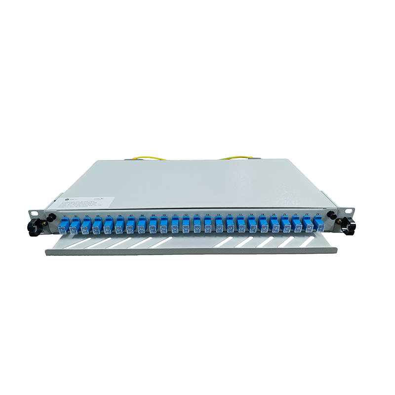
WM-ODF-24SC 19inch ODF
1. The Role of an Optical Distribution Frame in Modern Networks
An optical distribution frame, commonly known as an ODF, is a key passive component in a fiber-optic infrastructure. It provides a controlled location where optical cables can be introduced, fixed, spliced, terminated, distributed, and maintained. Without an organized ODF, individual fibers may become difficult to identify, vulnerable to bending or pulling, and challenging to repair or expand.
In a typical fiber installation, an outside cable enters an equipment room or cabinet. The cable must be mechanically secured before its internal fiber units are separated. The fibers are then routed through a protected path, spliced to pigtails, and connected to adapters on the front panel. Patch cords can subsequently connect the adapter ports to transmission equipment, network switches, optical line terminals, or other distribution equipment.
The ODF therefore performs several different tasks at once. It provides mechanical protection, optical organization, connection access, and cable-management discipline. It also creates a clear boundary between incoming network cables and equipment-side patching. This separation is essential when technicians need to test, reconfigure, isolate, or replace a connection.
The WM-ODF-24SC is intended for this type of structured deployment. Its 24-core capacity makes it suitable for small and medium fiber distribution points, access network nodes, equipment rooms, railway communication cabinets, enterprise networks, and other locations where a moderate number of fibers must be managed in a limited space.
Because the unit follows the 19-inch rack standard, it can be combined with optical transmission equipment, Ethernet equipment, power systems, monitoring devices, and other rack-mounted products. Standard mounting also reduces the need for specially fabricated cabinets, helping users create a consistent and scalable equipment-room layout.
2. Compact 1U Construction and Space Efficiency
One of the product’s main advantages is its 1U construction. The mechanical dimensions are approximately 43.6 millimeters in height, 482.6 millimeters in width, and 407 millimeters in depth. This format is compatible with the width of standard 19-inch racks and cabinets.
Space efficiency is increasingly important in communication rooms. Operators often need to install optical distribution equipment, switches, routers, power supplies, batteries, monitoring modules, and cable-management accessories in the same cabinet. A large or inefficient fiber panel can consume valuable rack space and limit future expansion.
The 1U format helps preserve vertical rack capacity while still providing room for fiber termination and splicing. Multiple units can be installed in the same cabinet when a project requires higher fiber counts. This modular approach enables network planners to begin with the capacity required for the initial deployment and add additional units as the network grows.
The compact format also supports installation in locations where floor space is restricted. These locations may include street-side cabinets, railway equipment rooms, data communication cabinets, building distribution rooms, industrial control rooms, and remote network nodes. By combining several fiber-management functions in one enclosure, the unit can help reduce the amount of separate hardware required.
Compared with larger free-standing fiber distribution cabinets, a 1U rack-mounted ODF can offer a more economical solution for moderate-capacity applications. It is easier to position close to active optical equipment, easier to integrate into existing cabinets, and simpler to include in standardized rack layouts.
Standardized Rack Compatibility
The 19-inch mounting design is an important practical advantage. Standard rack compatibility allows the ODF to be installed according to familiar cabinet engineering practices. Network designers can use existing racks, cabinet rails, mounting hardware, and cable-management systems without developing a new enclosure format for the optical distribution function.
Standardization also improves replacement and maintenance. If a unit must be removed, technicians can work with a known mounting arrangement. If the network is expanded, additional rack-compatible units can be installed using the same general cabinet architecture.
The front panel can be positioned alongside other 19-inch components, helping technicians identify optical connections from the front of the cabinet. The rear cable-entry area is used for incoming optical cable management, keeping the relationship between external cables and front-panel adapters organized.
3. Integrated Splicing and Distribution Functions
A major feature of the WM-ODF-24SC is the integration of splicing and distribution in one unit. In some network installations, separate splice boxes and distribution panels are used. While that arrangement may be suitable for large systems, it can increase the number of components, occupy more space, and make fiber routing more complicated.
By integrating the splice tray with the adapter panel, the product provides a direct path from the incoming optical cable to the terminated front-panel connection. The incoming cable is introduced through the rear of the unit, fixed in place, opened and prepared, and then routed through the fiber-management area. The individual fibers are spliced with pigtails inside the splice tray. The pigtails are subsequently connected to the SC adapters on the front panel.
This arrangement supports a clear division of functions. The cable-fixing area provides mechanical support. The fiber-routing area controls bend paths and slack. The splice tray provides a protected location for fusion or mechanical splicing operations. The adapter panel provides an accessible interface for patching and testing.
Integrating these functions can also reduce unnecessary fiber transitions. A shorter and more orderly internal fiber path may make the installation easier to inspect and troubleshoot. It also helps technicians understand the route followed by each fiber from the cable entry point to the corresponding adapter port.
The 24-core capacity is appropriate for applications that require a defined number of SC connections without the footprint of a larger high-capacity frame. It can be deployed for building-to-building links, access network distribution, optical equipment interconnection, railway communication subsystems, and small data-center or enterprise fiber systems.
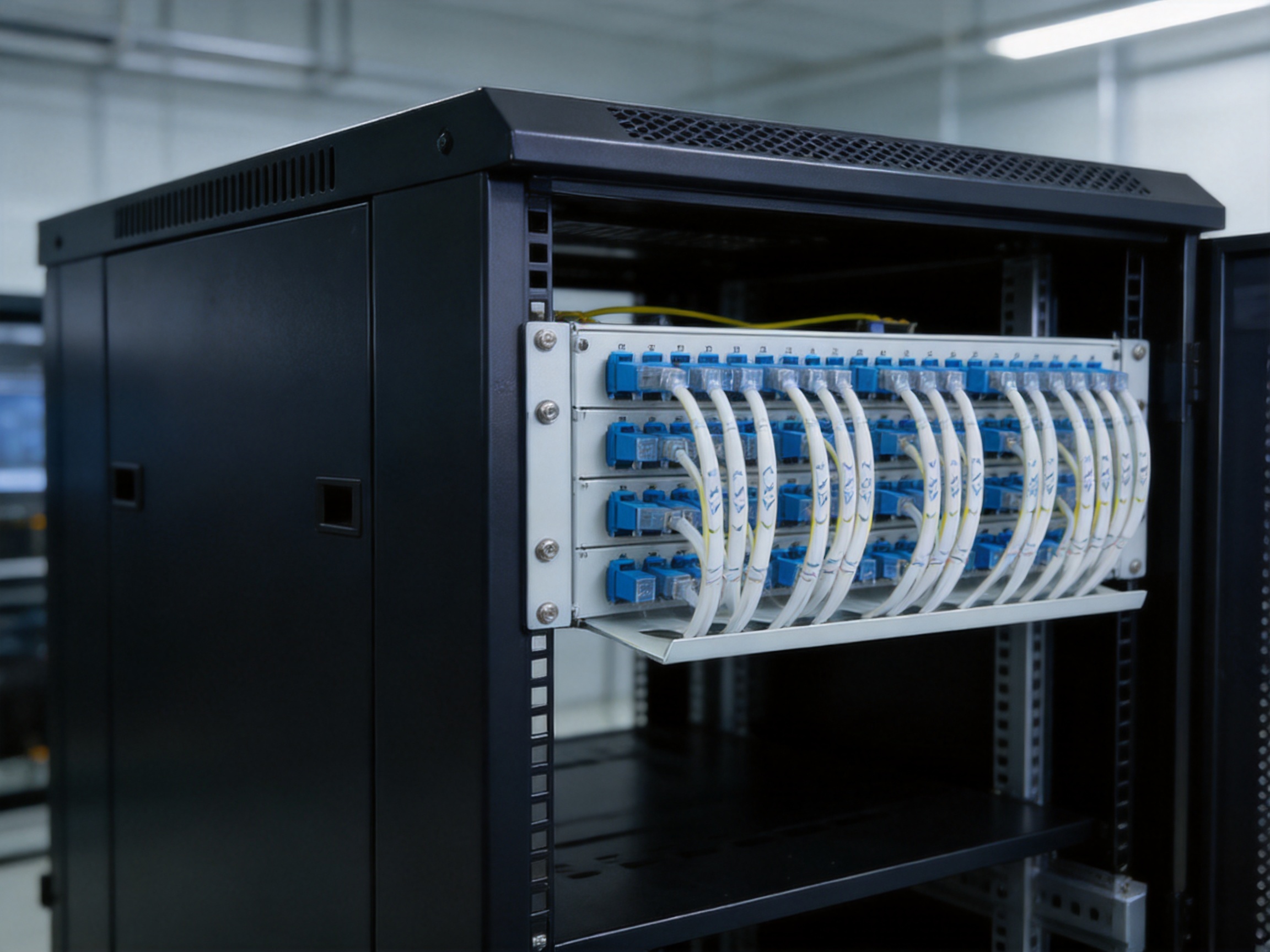
4. Materials and Structural Design
The adapter panel and primary ODF structure are made from metal material with a sprayed surface finish. This construction provides a stable mechanical platform for rack mounting, adapter installation, cable management, and repeated maintenance operations. The surface treatment also contributes to a clean and durable appearance suitable for professional equipment rooms.
Metal construction is useful in rack-mounted optical equipment because the enclosure must resist normal handling during installation, patching, and maintenance. The product may be removed, accessed, or adjusted many times over its service life. A rigid chassis helps maintain alignment between the mounting points, front adapter panel, drawer mechanism, and internal routing components.
The splice tray and cable guide are made from PP material. Polypropylene is lightweight and flexible, making it appropriate for internal fiber-management components that must guide cables without creating unnecessary stress. The use of a lighter material for these parts can help reduce the overall weight of the assembly while retaining the flexibility needed for routing.
The combination of a metal chassis and polymer internal accessories reflects a balanced product architecture. The metal components provide structural strength and rack stability, while the PP components support cable organization, controlled routing, and practical installation handling.
Surface Finish and Long-Term Usability
The sprayed surface finish contributes to protection against ordinary handling and environmental exposure within a suitable indoor equipment-room application. A consistent finish also makes the unit easier to inspect visually. Technicians can identify the equipment surface, mounting points, front-panel arrangement, and cable-management areas without the appearance of unfinished sheet metal.
For network operators, long-term usability is influenced not only by optical specifications but also by mechanical details. A product that is difficult to open, poorly organized, or vulnerable to cable movement can create maintenance problems even when its adapters and fibers meet optical requirements. The structure of this ODF is intended to support practical field work by combining a robust frame with accessible internal components.
5. Drawer-Type Access for Installation and Maintenance
The WM-ODF-24SC uses a drawer structure. The drawer can be pulled out during splicing and related operations, then returned to its normal position after the work is completed. This approach gives technicians access to the splice tray and internal fiber-routing area without requiring them to work deep inside a fixed enclosure.
Splicing inside a rack can be difficult when the splice area is located at the rear or is obstructed by adjacent equipment. A pull-out design brings the working area toward the technician. This can improve visibility, reduce awkward hand positions, and make it easier to organize fibers during installation.
The drawer also supports a more systematic workflow. A technician can pull out the unit, prepare the incoming cable, route fibers through the guide, complete the splice work, install protective sleeves, verify the fiber arrangement, and then return the drawer to its operating position. The sequence is straightforward and can be incorporated into standard installation procedures.
A limiting device is included to prevent excessive extraction. This is an important mechanical detail because optical fibers and pigtails can be damaged if a drawer is pulled beyond its intended travel. The limit helps control the movement of the assembly and reduces the risk of excessive tension, bending, or accidental disconnection.
The drawer mechanism is particularly valuable in cabinets where access from the rear is restricted. In many installations, the cabinet may be positioned close to a wall or adjacent equipment. Front-accessible drawer operation can make routine inspection and service easier than a design that requires full rear access.
Maintenance Benefits
Fiber networks are rarely static. Patch cords may be rerouted, equipment may be replaced, and new services may be added. Maintenance personnel must therefore be able to access the fiber-management area repeatedly without disturbing unrelated connections.
The drawer arrangement helps isolate the internal working area from the fixed rack position. When used correctly, it allows technicians to perform controlled work while preserving the order of the remaining rack equipment. It also supports visual inspection of splice sleeves, routing loops, pigtail paths, and adapter connections.
In comparison with a basic fixed panel, a controlled sliding or pull-out arrangement can offer a more convenient maintenance experience. The difference becomes especially significant in dense cabinets, where the available working space is limited.
6. Cable Fixation and Fiber Protection
Fiber optic cables are sensitive to excessive tension, sharp bends, compression, and uncontrolled movement. A high-quality distribution frame must therefore provide more than a termination point. It must support the cable mechanically and guide the individual fibers through safe paths.
The product includes a rear cable inlet and an optical cable splitting and fixing device. The incoming cable enters from the rear and is opened, peeled, and secured in the designated area. Fixing the cable before fiber separation helps prevent external pulling forces from being transferred directly to the splice points or pigtails.
After the cable is fixed, the fibers can be routed through the internal fiber spool or guide path. This controlled routing supports the management of slack and helps prevent fibers from being left loose inside the enclosure. Proper slack management is important because a fiber that is too tightly routed may experience stress, while uncontrolled excess length can interfere with the drawer or other components.
The included cable clamp provides additional mechanical support. Cable ties can be used to arrange and secure appropriate sections of the cable or protective tubing. Spiral protection tubing can help organize and protect fiber groups as they pass through the internal routing area.
Splice protection is supported by the use of heat-shrink protection tubes. The accessory list includes 45-millimeter heat-shrink tubes corresponding to the 24-core capacity. These tubes are used to protect splice points after the splice operation. The combination of splice sleeves, a dedicated tray, and controlled fiber routing creates a more secure internal environment than an unstructured termination area.
Fiber protection also involves maintaining suitable bend conditions. Although the supplied product information does not specify a single minimum bend radius for every cable type, installers should follow the cable manufacturer’s bend-radius requirements and applicable installation standards. The guides and tray should be used to avoid tight loops, sharp turns, and excessive pressure on the fibers.

7. SC Adapter Interface and Optical Performance
The product is configured for SC adapters. SC connectors are widely used in access networks, optical communication systems, building networks, and equipment-room installations. Their push-pull coupling style supports straightforward connection and disconnection, while the larger connector body can be convenient for identification and handling during field work.
The listed standard working wavelengths are 850 nanometers, 1310 nanometers, and 1550 nanometers. These wavelengths cover common multimode and single-mode optical communication applications, subject to the specifications of the installed cable, pigtails, transceivers, and network equipment.
The specified insertion loss is no greater than 0.3 decibels. Low insertion loss is important because every connector and adapter interface consumes part of the available optical power budget. A well-managed ODF should therefore provide stable adapter alignment and clean connector interfaces to help maintain network performance.
The stated return-loss values are PC at or above 40 decibels, UPC at or above 50 decibels, and APC at or above 60 decibels. Return loss describes the amount of optical power reflected toward the source. Higher return-loss values generally indicate lower reflected power. The appropriate connector polish type should be selected according to the transmission system and the mating components used in the installation.
These optical parameters make the product suitable for many passive fiber distribution applications. However, actual system performance depends on the complete optical link, including cable quality, splice loss, connector cleanliness, patch-cord specifications, adapter condition, and installation workmanship.
Connector Management in Practical Deployments
SC adapter panels allow technicians to identify and manage optical ports from the front of the rack. For a 24-core unit, clear labeling is recommended so that each adapter position corresponds to a documented cable, fiber number, destination, and service. Proper labeling reduces troubleshooting time and helps prevent accidental disconnection.
Connector cleaning should be part of every installation and maintenance procedure. Dust or contamination on an optical end face can increase insertion loss, reduce return performance, or damage mating surfaces. The ODF provides the physical organization needed for testing and patching, but technicians must still follow appropriate cleaning, inspection, and safety procedures.
8. Electrical and Insulation Characteristics
Although the ODF is a passive optical distribution product, its metal structure and electrical insulation characteristics are relevant to equipment-room safety and installation quality. The listed electric strength is at least 3 kilovolts DC for one minute, with no breakdown or arcing. The listed insulation resistance is at least 1,000 megohms at 500 volts DC.
These specifications provide reference points for electrical safety evaluation and quality inspection. The unit should be installed in accordance with the grounding and bonding requirements of the rack, cabinet, building, and applicable local standards. Where a metal rack is used, the installer should ensure that the equipment is integrated into the site’s approved protective-bonding system.
Electrical testing should be performed only by qualified personnel using appropriate procedures. Optical distribution equipment may be passive, but it is often installed alongside powered transmission equipment, power supplies, and other electrical systems. Good cabinet engineering should therefore address both optical organization and electrical safety.
The insertion life is specified as 500 times. This indicates the stated service expectation for repeated adapter insertion and removal under defined test conditions. In real installations, service life can be influenced by connector cleanliness, handling technique, adapter quality, patch-cord alignment, and environmental conditions.
9. Compatibility with Different Cable Types
The product is described as applicable to ribbon, bundle, and single-core cable. This flexibility is useful because network projects may use different cable constructions depending on fiber count, installation method, transmission requirements, and local engineering practice.
Ribbon cables group fibers in a flat arrangement and can support efficient high-density splicing. Bundle cables organize fibers in groups, while single-core cables provide individual fiber handling. The ODF’s splice tray and routing components must be used according to the structure of the selected cable and the recommended preparation method.
Installers should confirm that the cable diameter, strength member, fiber grouping, and entry method are compatible with the cable-fixing accessories. Proper preparation of the cable sheath and strength members is essential. The cable should be secured without crushing the internal fibers, and the transition from cable to loose fibers should be supported and protected.
The ability to accommodate several cable forms gives the ODF broader application value than a product designed for only one cable construction. It can be included in different project specifications while retaining the same general rack format and front-panel organization.
10. Accessory Package and Installation Readiness
The listed accessory package is designed to support a practical installation. It includes SC/UPC to LC/UPC optical patch cords in several lengths, SC/UPC to FC/UPC patch cords, SC/UPC pigtails, spiral protection tubing, heat-shrink tubes, cable clamps, snap nuts and screws, and cable ties.
The patch-cord selection includes 5-meter, 10-meter, and 15-meter lengths for SC/UPC to LC/UPC configurations, as well as a 10-meter SC/UPC to FC/UPC configuration. This range can help users connect the ODF to equipment with different connector interfaces and cabinet layouts. The exact accessory configuration should be confirmed for each project, especially where connector type, length, fiber mode, and polish specification are critical.
The package includes 24 SC/UPC 0.9-millimeter pigtails with a stated length of 3 meters. These pigtails are used to splice the incoming cable fibers to the front-panel adapter interface. The 24-count arrangement corresponds with the unit’s 24-core capacity.
Thirty meters of spiral protection tubing is listed for internal fiber organization. Twenty-four 45-millimeter heat-shrink tubes are included for splice protection. Two cable clamps, four sets of snap nuts and screws, and ten cable ties support mechanical installation and cable arrangement.
Providing these accessories with the main product can reduce the number of separate items that the installer must source. It also supports more consistent installation because the recommended fiber-management components are available as part of the product package. Nevertheless, project engineers should verify the final bill of materials and ensure that all accessories match the cable and connector requirements of the network.
Item |
Specification |
Purpose |
Rack format |
19-inch, 1U |
Installation in standard communication racks and cabinets |
Fiber capacity |
24 cores |
Splicing and distribution of up to 24 optical fibers |
Adapter type |
SC |
Front-panel optical termination and patching |
Dimensions |
43.6 mm × 482.6 mm × 407 mm |
Mechanical integration into 19-inch rack systems |
Working wavelengths |
850 nm, 1310 nm, 1550 nm |
Support for common optical communication windows |
Insertion loss |
≤ 0.3 dB |
Low-loss optical connection performance |
Return loss |
PC ≥ 40 dB; UPC ≥ 50 dB; APC ≥ 60 dB |
Reflection performance for different connector polish types |
Electric strength |
≥ 3 kV DC for 1 minute |
Electrical insulation and safety reference |
Insulation resistance |
≥ 1,000 MΩ at 500 V DC |
High-resistance insulation characteristic |
Insertion life |
500 times |
Repeated adapter connection and disconnection reference |
11. Working Environment and Deployment Conditions
The listed working temperature range is from -25 degrees Celsius to +40 degrees Celsius. The stated environmental temperature range extends from -40 degrees Celsius to +60 degrees Celsius, while the storage temperature range is from -25 degrees Celsius to +55 degrees Celsius.
The stated relative humidity is no greater than 85 percent at +30 degrees Celsius. The listed air-pressure range is 70 kilopascals to 106 kilopascals. These values provide important reference points for project planning, transportation, storage, and installation.
In practical terms, the ODF is suited to controlled indoor communication environments and appropriate cabinets where excessive moisture, condensation, dust, vibration, and temperature exposure are managed. If the product is used in a railway, industrial, outdoor, or semi-outdoor setting, the complete enclosure and environmental protection system must be evaluated, not just the ODF in isolation.
Equipment-room conditions can change significantly between installation and operation. A cabinet near a heating source, cooling outlet, external wall, or high-power device may experience localized temperature variations. Appropriate ventilation and cabinet planning help maintain conditions within the product’s specified range.
Storage also deserves attention. Optical components should be protected from moisture, contamination, impact, and extreme temperature. Packaging should remain intact until the equipment is ready for installation, and all adapter openings should be protected during transport and handling.
12. Manufacturing Strengths and Engineering Capability
Wanma Technology Co., Ltd. was established in 1997 and specializes in communication cabinets, communication electronic equipment, and passive optical components. This background is relevant to the development of an ODF because the product combines sheet-metal structure, rack integration, optical connection management, fiber splicing, and passive component application.
The company’s product scope covers equipment used in Ethernet networks, optical communication networks, central equipment rooms, national high-speed railways, and urban rail transit systems. These application environments require products that are practical to install, stable in operation, consistent in quality, and suitable for structured deployment.
The company develops, manufactures, and markets its own branded products while also providing integrated solutions for customized products. This combination can be valuable for network projects that require both standard catalog equipment and adaptations for particular cabinet sizes, connector arrangements, cable entries, or deployment conditions.
A manufacturing organization with experience in communication cabinets can coordinate mechanical design with optical requirements. For an ODF, this includes ensuring that the rack dimensions, drawer travel, cable entry, adapter panel, splice tray, and internal guides work together as one system. Mechanical accuracy is important because small alignment errors can affect installation convenience, fiber routing, and front-panel access.
Controlled Product Development
Product development for passive optical equipment should begin with application requirements. Engineers must consider the number of fibers, connector type, cable construction, rack space, access direction, splice protection, maintenance method, environmental conditions, and expected service life.
For the WM-ODF-24SC, these requirements are reflected in the 1U rack form, 24-core capacity, SC adapter configuration, drawer structure, rear cable entry, cable-fixing arrangement, and internal fiber protection accessories. The result is a product designed around a defined installation workflow rather than a simple panel with adapter openings.
Manufacturing quality also involves repeatability. Each unit must maintain consistent dimensions, mounting-hole positions, surface treatment, adapter alignment, drawer movement, and accessory compatibility. Consistency helps installers use the same procedures across multiple cabinets and reduces uncertainty during deployment.
Integration of Metal and Polymer Components
The product uses metal for the main chassis and adapter panel and PP for the splice tray and cable guide. Manufacturing these different parts requires material selection, forming or molding processes, surface finishing, assembly control, and inspection.
The metal frame must provide sufficient rigidity for rack mounting and repeated drawer operation. The PP components must fit correctly within the frame and guide fibers without sharp edges or excessive restriction. The interaction between the two material groups is important because a strong chassis alone does not guarantee good fiber management.
Attention to these interfaces is one way a specialized manufacturer can distinguish a practical ODF from a basic low-cost enclosure. The product’s value lies not only in the raw materials but also in how the parts are designed and assembled to support installation and maintenance.
13. Advantages Compared with Basic or Less Integrated Alternatives
The first advantage is functional integration. A basic adapter panel may provide front-panel termination but no dedicated splice tray, cable-fixing area, or controlled fiber-routing path. The WM-ODF-24SC combines these functions in one rack unit, reducing the need for separate splice and distribution hardware.
The second advantage is space efficiency. A 1U enclosure can preserve cabinet capacity for active network equipment and future expansion. In applications with 24 or fewer optical cores, a larger cabinet may be unnecessary.
The third advantage is maintainability. The pull-out drawer provides access to the splice area and includes a limiting device to control extraction. This can be more convenient than a fixed internal tray, especially when the rack is dense or rear access is restricted.
The fourth advantage is mechanical organization. The rear cable inlet, cable clamp, cable guide, spiral protection tubing, heat-shrink tubes, and cable ties work together to support a structured fiber path. This is preferable to leaving cable strength members, splice points, and pigtails loosely arranged within a cabinet.
The fifth advantage is deployment flexibility. The unit is compatible with ribbon, bundle, and single-core cable types, and it uses a widely adopted SC adapter interface. This allows it to serve multiple network architectures while maintaining a consistent rack-mounted format.
The sixth advantage is specification transparency. The product information identifies its dimensions, capacity, insertion loss, return-loss values, working wavelengths, electrical characteristics, environmental conditions, and insertion life. Clear specifications help engineering teams compare the unit with project requirements before procurement.
Finally, the manufacturer’s experience in communication equipment and passive optical components supports a more complete understanding of the deployment environment. The company’s involvement in Ethernet, optical communication, railway, and urban rail transit applications provides a foundation for serving projects where mechanical and optical infrastructure must operate together.

14. Applications in Different Network Environments
Ethernet and Enterprise Networks
Enterprise buildings often use fiber links between equipment rooms, floors, buildings, and campus distribution points. The ODF can provide a clear termination point for incoming fiber cables and patch-cord connections to Ethernet switches or optical uplink equipment.
The 1U footprint is useful in server rooms and communications closets where rack space is limited. The front adapter panel can be labeled by floor, building, service, or switch port, while the rear area can be reserved for cable entry and splicing.
FTTH and Access Network Infrastructure
Fiber-to-the-home and broadband access systems require organized distribution points between feeder cables, distribution cables, and active or passive optical equipment. A 24-core ODF can serve a localized access node, building distribution point, or smaller subscriber concentration area.
Because access networks are frequently expanded and reconfigured, the ability to inspect and maintain the splice and patching area is valuable. The drawer structure can support controlled access during service activation, repair, and capacity upgrades.
Railway and Urban Rail Transit
Railway and urban rail transit networks use optical communication systems for signaling support, passenger information, surveillance, operations control, telephony, and other services. Equipment may be installed in communication rooms, station cabinets, technical buildings, and trackside facilities.
In these environments, clear fiber organization is important because multiple systems may share the same communications infrastructure. A rack-mounted ODF can help separate incoming cable management from equipment-side patching and support a documented connection structure.
Actual use in railway or transit environments must account for project-specific requirements concerning vibration, shock, electromagnetic compatibility, fire performance, temperature, humidity, and enclosure protection. The ODF should be evaluated as part of the complete system design.
Central Equipment Rooms
Central equipment rooms often contain large numbers of optical cables and active network devices. The product can be installed as part of a modular fiber-management strategy, with multiple 1U units used to serve different cable groups, network segments, or customer interfaces.
Its standard width enables integration into cabinets that already contain switches, routers, optical transport equipment, and power distribution components. The compact arrangement can assist with orderly cabinet planning and reduce unnecessary cable travel.
Industrial and Specialized Communication Systems
Industrial communication systems may require fiber connections between control rooms, production areas, substations, or remote monitoring locations. Optical fiber offers immunity to electromagnetic interference and supports long-distance communication, but the fiber-management hardware must still be installed carefully.
The ODF can provide a centralized point for fiber splicing and patching, helping maintenance personnel identify connections during system upgrades or troubleshooting. Site engineers should confirm that the operating environment meets the product’s stated conditions and that the cabinet provides appropriate protection.
15. Recommended Installation Practices
Before installation, inspect the ODF, accessories, adapter openings, splice tray, drawer mechanism, mounting hardware, and cable-entry area. Check that the product has not been damaged during transport and that protective caps remain in place until optical connections are ready.
Install the unit in a clean, stable 19-inch rack or cabinet. Confirm that the rack rails are correctly aligned and that the mounting hardware is tightened without deforming the chassis. The cabinet should provide sufficient space for the drawer to extend safely and for the incoming cable to enter without excessive bending.
Route the optical cable from the rear and secure it with the cable-fixing device. The cable should be supported before its fibers are separated. Avoid transferring pulling force to the pigtails, splice sleeves, or adapter panel.
Prepare the cable according to the cable manufacturer’s instructions. Route the fibers through the internal guide or spool, maintain appropriate slack, and avoid tight bends. Splice each fiber to the corresponding pigtail, install the heat-shrink protection sleeve, and place the protected splice in the appropriate tray position.
Use spiral protection tubing and cable ties where appropriate, but do not overtighten ties around optical fibers. Excessive compression can create unwanted stress. Keep the drawer path clear and confirm that the fibers do not become pinched when the drawer is moved.
Connect the pigtails to the SC adapters and label each port. Clean and inspect connector end faces before mating. After installation, test the fibers using suitable optical test equipment and record insertion loss, continuity, and other required measurements.
Finally, return the drawer to its operating position and verify that the limiting mechanism works correctly. Confirm that no cable or pigtail is under tension and that the front-panel patch cords are routed with suitable bend protection.
16. Maintenance and Service Considerations
Routine maintenance should include visual inspection of the front adapter panel, patch cords, cable entry, splice tray, and drawer mechanism. Technicians should look for excessive cable tension, damaged protective tubing, loose mounting hardware, contamination, or unusual fiber bends.
Optical connectors should be cleaned before reconnection. Unused adapter ports should remain protected with dust caps. Patch cords should not be bent below their specified minimum bend radius, and they should be routed so that cabinet doors, drawers, and other equipment cannot crush them.
The drawer should be operated smoothly and only as far as permitted by the limiting device. Forcing the drawer beyond its intended travel can damage the mechanism or place stress on internal fibers. If resistance is encountered, technicians should stop and inspect the fiber path rather than applying additional force.
Network documentation should identify each cable, fiber, pigtail, adapter port, and connected device. Accurate records help reduce service interruption when changes are required. The compact size of the unit makes labeling particularly important because multiple ports may be positioned close together.
Maintenance personnel should also monitor environmental conditions. Excessive humidity, condensation, dust, or temperature can affect optical performance and mechanical reliability. The rack or cabinet should be kept clean and appropriately ventilated.
17. Procurement and Project Selection Guidance
When selecting an ODF, project engineers should begin by confirming the required fiber capacity. The WM-ODF-24SC is designed for 24 cores, so larger networks may require multiple units or a higher-capacity platform. The project should also confirm whether SC connectors are required or whether another connector format is preferred.
The cable type should be reviewed before ordering. Ribbon, bundle, and single-core cables may require different preparation methods and accessories. Cable diameter, strength-member design, entry direction, and splice organization should be considered during cabinet planning.
Engineers should verify the optical performance requirements of the complete link. The listed insertion-loss and return-loss values provide a product reference, but the final link budget must include cable attenuation, splice loss, patch-cord loss, connector loss, and the requirements of the active equipment.
Environmental and mechanical requirements should also be evaluated. If the ODF will be installed in a railway, industrial, outdoor, or high-vibration location, the complete installation system may require additional protection beyond the standard rack-mounted unit.
Finally, customers should review the accessory package and determine whether the listed patch cords, pigtails, protection tubes, cable clamps, mounting hardware, and cable ties match the project bill of materials. Wanma Technology’s ability to provide standardized products and customized integrated solutions can be useful when the project requires specific arrangements.
18. Quality, Delivery, and Partnership Value
For communication infrastructure projects, product quality is only one part of procurement value. Delivery reliability, technical communication, documentation, customization capability, and after-sales coordination also influence the success of a deployment.
Wanma Technology emphasizes reliable product quality, timely delivery, and long-term strategic partnerships with industry leaders. Its sales network covers more than 20 countries and regions, including the United States, Australia, the United Kingdom, Italy, South Africa, and Ghana.
International project support requires attention to specification clarity and communication. Product dimensions, optical parameters, accessory configurations, environmental conditions, and installation requirements should be documented before production and shipment. This helps customers align the product with local cabinet standards and project acceptance procedures.
The company’s experience in developing and marketing its own products allows it to maintain a direct relationship between product design and customer application. At the same time, its integrated-solution capability can support projects that need modified designs or coordinated communication infrastructure products.
19. Q&A
Q1: What is the capacity of the WM-ODF-24SC?
The unit has a capacity of 24 optical cores and is configured as a 1U rack-mounted optical distribution frame.
Q2: Can it be installed in a standard communication rack?
Yes. It is designed for a 19-inch standard rack or cabinet. Its listed dimensions are approximately 43.6 millimeters high, 482.6 millimeters wide, and 407 millimeters deep.
Q3: What connector type does the product use?
The product is configured for SC adapters. The accessory list also includes patch cords with LC and FC connector interfaces for connection to different types of network equipment.
Q4: Does the unit support fiber splicing?
Yes. It includes a splice tray and internal fiber-routing structure. Incoming cable fibers are spliced with pigtails inside the tray before being connected to the front-panel adapters.
Q5: How does the drawer structure help technicians?
The drawer can be pulled out during splicing and maintenance, bringing the working area forward for easier access. A limiting device helps prevent excessive extraction that could damage internal fibers.
Q6: What cable types can be used with this ODF?
The product is described as applicable to ribbon, bundle, and single-core cable. The installer should still verify cable dimensions and preparation requirements before deployment.
Q7: What are the specified optical performance values?
The listed insertion loss is no greater than 0.3 decibels. Return loss is specified as PC at or above 40 decibels, UPC at or above 50 decibels, and APC at or above 60 decibels.
Q8: Which operating wavelengths are supported?
The standard working wavelengths are 850 nanometers, 1310 nanometers, and 1550 nanometers.
Q9: What materials are used in the construction?
The adapter panel and main ODF structure are made from metal with a sprayed surface. The splice tray and cable guide are made from PP material.
Q10: What accessories are included?
The listed accessories include optical patch cords, 24 SC/UPC pigtails, spiral protection tubing, heat-shrink tubes, cable clamps, snap nuts and screws, and cable ties. The exact package should be confirmed for the specific order.
Q11: Is the product suitable for railway and urban rail transit applications?
It can be considered for suitable fiber-management applications in railway and urban rail transit systems. However, the complete project must evaluate vibration, shock, environmental, fire, electromagnetic, and enclosure requirements.
Q12: What should be considered when maintaining the unit?
Technicians should keep connectors clean, protect unused ports, avoid excessive fiber bending, inspect the cable-fixing area, operate the drawer carefully, and maintain accurate port and fiber documentation.
Q13: Can the manufacturer provide customized solutions?
Wanma Technology develops and manufactures its own products and also provides integrated solutions for customized products. Project-specific requirements should be discussed and confirmed before production.
20. Conclusion
The WM-ODF-24SC 19-inch Optical Distribution Frame is a compact and integrated solution for organizing, splicing, protecting, and distributing up to 24 optical fibers. Its 1U rack format helps conserve cabinet space, while its standard 19-inch construction supports straightforward installation in communication racks and cabinets.
The combination of a metal chassis, PP splice tray and cable guide, rear cable-fixing area, drawer structure, limiting device, SC adapter interface, and splice-protection accessories gives the product practical value beyond a simple fiber termination panel. These features are designed to support a controlled installation workflow and easier long-term maintenance.
Its specified optical characteristics, working wavelengths, environmental conditions, electrical insulation values, and insertion life provide useful reference points for project engineering. The product can be considered for Ethernet networks, FTTH infrastructure, central equipment rooms, enterprise fiber systems, railway communications, urban rail transit, and other applications requiring organized passive optical management.
Wanma Technology’s experience in communication cabinets, communication electronic equipment, and passive optical components strengthens the product’s application relevance. Its manufacturing background, international sales experience, customization capability, and focus on quality and delivery make it a suitable partner for network infrastructure projects that require dependable fiber-management equipment.
For best results, the ODF should be installed by qualified personnel, used within its specified conditions, and integrated into a complete network design that addresses optical budgets, cable compatibility, environmental protection, grounding, labeling, testing, and maintenance. When these factors are properly managed, the WM-ODF-24SC can provide an orderly foundation for reliable and serviceable fiber connectivity.
References
1. Product technical information for the WM-ODF-24SC 19-inch Optical Distribution Frame, including mechanical, optical, electrical, environmental, and accessory specifications.
2. General principles of optical fiber splice protection, cable routing, connector cleaning, and fiber distribution-frame installation.
3. Industry practices for 19-inch rack-mounted communication equipment and structured optical network cabinets.
4. General engineering guidance for optical link budgets, insertion loss, return loss, connector performance, and fiber maintenance.
5. Manufacturer information concerning communication cabinets, passive optical components, Ethernet networks, railway communications, and urban rail transit applications.
Product: WM-ODF-24SC 19inch ODF
PREV:Outdoor Telecom Cabinets for Copper-to-Fibre Network Modernisation
NEXT:Mechanical Fiber Splice Solutions for Reliable Optical Network Deployment
NEXT:Mechanical Fiber Splice Solutions for Reliable Optical Network Deployment
Interested in cooperation or have questions?
Related products
-
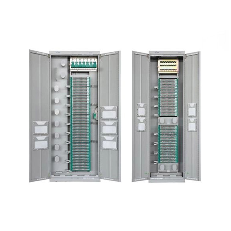
-
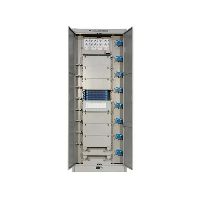
Application ScopeThe GPX129BKC fiber optic distribution frame is used to connect and distribute optical cables to optical communication equipment, and is suitable for large-capacity fiber optic commun...
See Details -
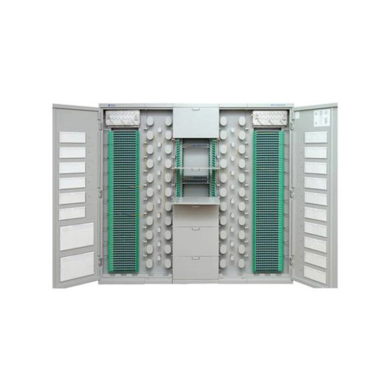
Application Used in FTTH network access-layer equipment rooms where splitting, splicing, distribution and other operations need to be carried out within a frame. Used in FTTH networks where optical sp...
See Details -
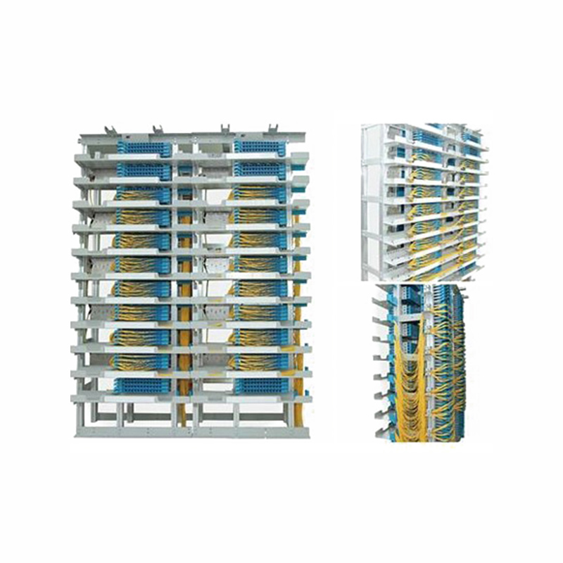
Application Used in independent fiber patching areas of newly built communication equipment rooms and central equipment rooms. After cable removal, the original main distribution frame is dismantled, ...
See Details
Ready to Get started ? Contact Us Now !

Product.
Contact Details.
-
 +86 13958188250
-
 +86 13958188250
-
 [email protected]
-
 AUDIT Email:[email protected]
- Wanma Industrial Park Taihu Yuan Town Lin'an District Hangzhou City China.
QR Code

Copyright © Wanma Technology Co., Ltd. All Rights Reserved.
Privacy
Custom Ethernet Optical Network Railway Transit Equipments Suppliers
