

 English
 Français
 Español
 Português
 عربى







Application:It is used to allow connection between Φ0.90 /Φ0.25 mm optical fibers or 2 3 Bow-type optical cables in optical cable splice closure, optical cable distribution box, and optical fiber sock...
See DetailsMechanical Fiber Splice Solutions for Reliable Optical Network Deployment
Content
- 1 Introduction
- 2 Product Purpose and Application Scope
- 3 Core Design Features
- 4 Performance Advantages Compared with Alternative Connection Methods
- 5 Manufacturing Approach and Process Strengths
- 6 Installation Principles
- 7 Application in Closures, Distribution Boxes, and Fiber Sockets
- 8 Reliability and Lifecycle Benefits
- 9 Benefits for Contractors and Network Operators
- 10 Selection Considerations
- 11 Recommended Quality and Handling Practices
- 12 Why This Mechanical Splice Is a Practical Competitive Choice
- 13 Q&A
- 13.1 What is a mechanical fiber splice?
- 13.2 Which fibers can this product connect?
- 13.3 Where can the splice be installed?
- 13.4 What is the purpose of the V-shaped slot?
- 13.5 How does mechanical crimping help?
- 13.6 Why does the product include storage rooms for matching fluid?
- 13.7 Can the splice be reopened?
- 13.8 Is a mechanical splice better than fusion splicing in every application?
- 13.9 Does the splice eliminate the need for optical testing?
- 13.10 What should users consider when selecting the product?
- 13.11 What manufacturing strengths support the product?
- 13.12 Can the product support railway communication projects?
- 14 Conclusion
- 15 References
- 16 Product: Fiber Solution-Mechanical Splice
Introduction
Reliable fiber connectivity is essential to modern telecommunications infrastructure. As optical networks expand into residential broadband, enterprise communications, railway systems, urban rail transit, data centers, and industrial facilities, network operators need connection technologies that are consistent, compact, serviceable, and suitable for field deployment. A mechanical fiber splice provides a practical way to join optical fibers without requiring a permanent fusion-splicing process or complex electrical equipment.
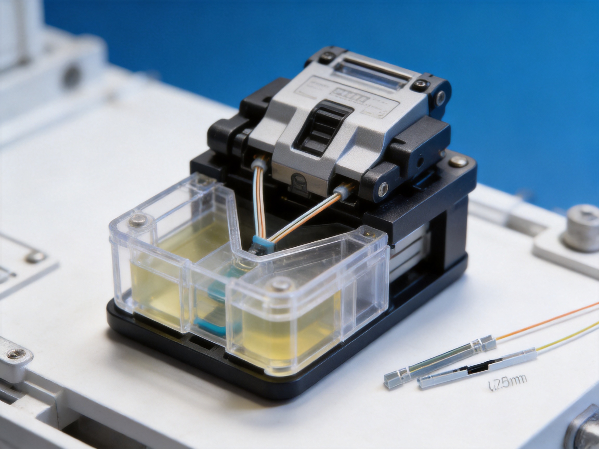
The Fiber Solution-Mechanical Splice is designed for connecting Φ0.90 mm and Φ0.25 mm optical fibers, as well as two or three bow-type optical cables. It is suitable for use inside optical cable splice closures, optical cable distribution boxes, optical fiber sockets, and other passive optical network enclosures. Its design combines a precision V-shaped alignment slot, mechanical crimping technology, and a replenishable matching-fluid system to support low insertion loss, stable performance, and extended service life.
Mechanical splicing is especially valuable when installation speed, portability, serviceability, and operational flexibility are important. Technicians can use the splice in locations where fusion-splicing equipment is unavailable, where power access is limited, or where a connection may need to be reopened for inspection or rearrangement. These benefits make the product suitable for network construction, maintenance, emergency restoration, and structured fiber distribution.
The product is manufactured and supplied by a telecommunications equipment company with experience in communication cabinets, communication electronic equipment, and passive optical components. Its products serve Ethernet networks, optical communication networks, central equipment rooms, high-speed railways, and urban rail transit systems. This application background supports a product philosophy based on practical installation, dependable operation, compatibility with network infrastructure, and long-term customer service.
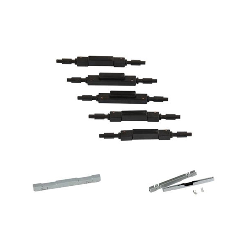
Fiber Solution-Mechanical Splice
Product Purpose and Application Scope
A mechanical splice is a passive optical component that holds and aligns two optical fibers so that light can pass from one fiber to the other with minimal disruption. Unlike an electrical connector, it does not transmit electrical current or require an electronic signal-processing circuit. Its purpose is to maintain accurate fiber alignment and provide a stable optical interface within a protected enclosure.
The Fiber Solution-Mechanical Splice is intended for several common network conditions. It can connect optical fibers with a diameter of Φ0.90 mm or Φ0.25 mm, allowing the product to support different fiber protection and cable preparation arrangements. It can also be used with two or three bow-type optical cables, making it suitable for selected cable distribution and branch connection applications.
Typical installation locations include optical cable splice closures, optical cable distribution boxes, and optical fiber sockets. These locations are found throughout access networks and communication infrastructure. A splice closure may use the product to organize a repaired or extended cable route. A distribution box may use it to connect incoming and outgoing fiber paths. An optical fiber socket may use it to provide a compact connection point near the user or equipment side of a network.
The product can also support maintenance activities. When a network route is modified, a technician may need to replace a cable section, reconnect a fiber, or inspect a previous joint. The ability to reopen the splice reduces the need to discard the complete connection assembly. This can simplify repair work and help reduce material waste during network upgrades.
Telecommunications Networks
Telecommunications networks often contain large numbers of fiber connections spread across central offices, equipment rooms, outdoor cabinets, distribution points, and customer access locations. Each connection must be organized and protected while remaining accessible for installation and maintenance.
A compact mechanical splice is useful in these environments because it can be placed inside a suitable enclosure without requiring a large working area. The V-shaped slot helps position the fibers, while the mechanical crimping structure holds them in alignment. These characteristics are helpful when technicians need to complete a connection efficiently in a cabinet or closure.
FTTH and Access Networks
Fiber-to-the-home and related broadband networks require flexible connection methods. Installation conditions may vary from a controlled equipment room to a narrow outdoor distribution box or a residential fiber socket. A mechanical splice can help installers respond to different site conditions without carrying a full range of powered splicing equipment.
The compatibility with Φ0.90 mm and Φ0.25 mm fibers is relevant to access networks because fiber assemblies may use different protective structures. The splice can be selected for applications where a compact connection and straightforward field handling are more important than a permanent factory-sealed joint.
Railway and Urban Transit Infrastructure
Railway communication systems and urban rail transit networks depend on dependable fiber links for communications, control, monitoring, passenger information, security, and operational coordination. These systems may include long cable routes, equipment cabinets, stations, tunnels, maintenance rooms, and trackside installations.
In these environments, technicians value connection products that are easy to install, consistent in performance, and suitable for organized enclosure layouts. The mechanical splice is applicable to passive optical assemblies associated with railway and transit communication infrastructure, provided that the complete installation complies with the project’s environmental, mechanical, and safety requirements.
Core Design Features
Two Splice Types for Flexible Deployment
The product family includes two basic configurations: an optical fiber splice and an optical cable splice. This division allows users to select a solution according to the construction of the fiber or cable being connected.
An optical fiber splice is intended for direct fiber-to-fiber connection. It is suitable when the prepared fiber ends need to be aligned and secured in a compact mechanical structure. An optical cable splice is intended for applications involving protected cable structures and bow-type optical cables. Offering both types makes the product more adaptable than a single-format solution.
Using the correct splice type can simplify installation planning. Network designers and contractors can match the component to the cable construction, enclosure layout, and maintenance method. This reduces the risk of using an unsuitable connection format and supports more consistent deployment across different network sections.
V-Shaped Alignment Slot
The V-shaped slot is one of the product’s central design elements. A V-slot provides two inclined surfaces that guide the optical fiber toward a stable central position. When the fiber is placed in the slot, the geometry helps restrict unwanted lateral movement and supports repeatable alignment.
Accurate alignment is essential because the optical core is extremely small. Even a small offset between two fiber ends can increase optical loss or reduce connection consistency. The V-shaped structure therefore serves both a positioning and a stability function. It helps the fiber remain closely attached to the slot during mechanical securing and subsequent handling.
Compared with a less controlled positioning method, a well-designed V-slot can offer a more predictable assembly process. It gives the technician a defined placement path and reduces dependence on visual judgment alone. This is particularly useful during field installation, where working conditions may not be as controlled as those in a laboratory or factory.
Mechanical Crimping Technology
The product uses mechanical crimping technology to secure the optical fiber after alignment. Mechanical crimping applies controlled physical pressure to hold the fiber in the intended position. When combined with the V-slot, it helps preserve concentricity between the two connected fiber ends.
Good concentricity means that the two fiber cores are positioned as closely as possible along the same optical axis. This supports low insertion loss and helps maintain consistency from one connection to another. It also reduces the likelihood that ordinary handling or vibration will create a significant change in the connection position.
Mechanical crimping provides an important advantage in field applications. The installation method is based on physical positioning and securing rather than on a permanent thermal fusion process. This can reduce equipment requirements and make the product practical for repair teams, service contractors, and projects where installation speed is a priority.
Matching Fluid Storage and Replenishment
The product includes storage rooms on both sides of the splice. These storage areas supplement the matching fluid and deliver it to the splicing point through a pump action. The matching fluid helps reduce the optical discontinuity between the connected fiber ends and supports stable optical transmission.
Over time, the condition and availability of matching fluid can influence splice performance. A design that stores additional fluid and directs it to the splicing point helps support a longer operating life than a structure that depends only on a small initial quantity. This feature is particularly relevant to networks expected to remain in service for many years.
The replenishment concept also contributes to performance consistency. Instead of relying solely on the original fluid position, the internal structure can supply the splicing point as needed within the product’s intended operating mechanism. The result is a more durable approach to maintaining the optical interface.
Reopenable Construction
The mechanical splice can be reopened. This is a valuable advantage for network maintenance and configuration changes. A permanent connection may need to be cut or replaced when an adjustment is required, whereas a reopenable mechanical structure can allow inspection, correction, or reconnection.
Reopenability can reduce maintenance time and material consumption. It may also help technicians recover from an installation error without replacing the entire cable section. For networks that undergo frequent changes, additions, and repairs, this flexibility can improve lifecycle efficiency.
Reopening must always be performed according to the applicable installation procedure. The fiber ends, matching-fluid condition, alignment surfaces, and enclosure protection should be checked before the splice is returned to service. Proper handling is essential to preserve the low-loss performance expected from the product.
Performance Advantages Compared with Alternative Connection Methods
Different fiber connection technologies are appropriate for different applications. Fusion splicing can provide a highly permanent joint when specialized equipment, trained personnel, stable power, and controlled preparation conditions are available. Conventional connectors can provide repeated mating and unmating but may require connectorized cable ends, adapters, and additional space. Mechanical splicing occupies a practical position between these approaches.
The Fiber Solution-Mechanical Splice offers several advantages for situations where installation flexibility and serviceability are important.
| Evaluation Area | Mechanical Splice Advantage | Practical Benefit |
|---|---|---|
| Installation equipment | Uses mechanical alignment and crimping | Reduces dependence on fusion-splicing equipment |
| Fiber alignment | V-shaped slot supports stable positioning | Helps maintain concentricity and consistent optical performance |
| Optical stability | Matching-fluid storage supports the splicing point | Contributes to long service life and low insertion loss |
| Maintenance | Reopenable construction | Allows inspection, correction, and reconnection |
| Compatibility | Supports Φ0.90 mm and Φ0.25 mm fibers and selected bow-type cables | Provides flexibility across network assemblies |
| Deployment environment | Designed for closures, distribution boxes, and fiber sockets | Fits common passive optical infrastructure |
| Field productivity | Compact mechanical installation method | Supports efficient work in cabinets and enclosures |
Advantage over Permanent Fusion-Only Approaches
Fusion splicing remains an important technology, but it may not be the most efficient choice for every connection. Fusion splicers are precision instruments that require equipment investment, maintenance, battery management, cleaning, calibration, and operator training. In remote locations or emergency situations, transporting and operating this equipment can slow down restoration work.
A mechanical splice can be installed using a more portable process. This does not mean that it replaces fusion splicing in every application. Instead, it provides an alternative when speed, accessibility, or reopenability is more important than creating a permanent fused joint. It is particularly useful for selected enclosure-based connections and field repairs.
Advantage over Basic Fixed Mechanical Designs
Some mechanical connection methods may depend on a single application of matching fluid or provide limited options for reopening. The storage rooms and replenishment mechanism in this product address the need for longer-term fluid support. The ability to reopen the splice also provides a maintenance advantage over designs intended to be used only once.
The combination of V-slot alignment, mechanical crimping, and fluid replenishment is important. Each feature supports a different part of the connection process: the slot helps position the fiber, the crimping system secures it, and the fluid system supports the optical interface. Together, these features create a more complete mechanical splicing solution than a simple fiber-holding clip.
Advantage in Network Lifecycle Management
Network infrastructure is rarely static. Cables may be rerouted, customers may be added, equipment may be replaced, and transport communication systems may be upgraded. A reopenable splice supports this changing environment by allowing the connection to be accessed when necessary.
Lifecycle flexibility can lower the practical cost of ownership. The benefit is not limited to the initial purchase price. It also includes installation labor, troubleshooting time, replacement material, emergency restoration speed, and the ability to adapt an existing enclosure to new network requirements.
Manufacturing Approach and Process Strengths
Reliable mechanical splicing depends on accurate component geometry, stable material quality, consistent assembly, and appropriate inspection. The product’s performance is closely related to the precision of its V-slot, the repeatability of its crimping structure, and the dependable operation of its matching-fluid storage system.
The manufacturer’s experience in passive optical components provides a foundation for producing products that must operate without active electronic control. Passive components require careful attention to dimensional accuracy, assembly cleanliness, fiber handling, packaging, and compatibility with optical network enclosures.
Precision-Oriented Component Production
The V-shaped alignment slot must maintain a controlled geometry so that the fiber can be positioned consistently. The crimping components must apply sufficient holding force without damaging the fiber or creating an unstable connection. The storage rooms and internal fluid path must also be formed and assembled correctly to support the intended replenishment function.
These requirements encourage a precision-oriented manufacturing process. Component forming, molding, machining, or assembly operations must be controlled so that every part performs its intended role. Dimensional consistency is especially important when products are installed in large quantities across a network.
Controlled Assembly
Mechanical splice assembly involves more than putting components together. The alignment surfaces must remain clean, the moving or crimping parts must operate correctly, and the internal fluid system must be assembled without blockage or leakage. Controlled assembly procedures help reduce variation between individual units.
A disciplined assembly process also supports easier installation by the customer. When the product is manufactured consistently, technicians can follow a repeatable installation method. Predictable product behavior reduces the need for improvised adjustments and helps contractors maintain consistent work quality across multiple sites.
Quality-Oriented Inspection
Inspection is an essential part of manufacturing passive optical products. The product should be evaluated for physical integrity, alignment behavior, crimping function, reopenability, and optical performance according to the applicable product and project requirements.
Low insertion loss and consistency are stated product characteristics. These characteristics depend on the relationship between the fiber placement surfaces, mechanical securing structure, and matching-fluid system. Quality inspection therefore needs to consider both mechanical and optical aspects rather than examining appearance alone.
For network operators, consistent manufacturing is important because a project may require many splice units. A single acceptable sample does not guarantee reliable network deployment unless production is controlled across the entire order. Manufacturing experience, process discipline, and an established quality culture help support repeatability.
Integrated Product Development
The company develops, manufactures, and markets products under its own brand while also providing integrated solutions for customized products. This structure can help connect product design with manufacturing feedback and customer application requirements.
For a mechanical splice, integrated development is valuable because the product must work within broader systems. It may be installed in a splice closure, distribution box, socket, communication cabinet, or transit infrastructure enclosure. Understanding these surrounding systems can help guide product dimensions, installation methods, packaging, and compatibility decisions.
Manufacturing Experience in Communication Infrastructure
The manufacturer was established in 1997 and specializes in communication cabinets, communication electronic equipment, and passive optical components. This long-term industry presence provides experience in the practical requirements of telecommunications infrastructure, including product reliability, enclosure integration, delivery coordination, and project support.
Its products are used in Ethernet networks, optical communication networks, central equipment rooms, national high-speed railways, and urban rail transit systems. These application areas require products that can be integrated into organized infrastructure and maintained over long service periods. The mechanical splice benefits from being developed within this broader telecommunications product environment.
Installation Principles
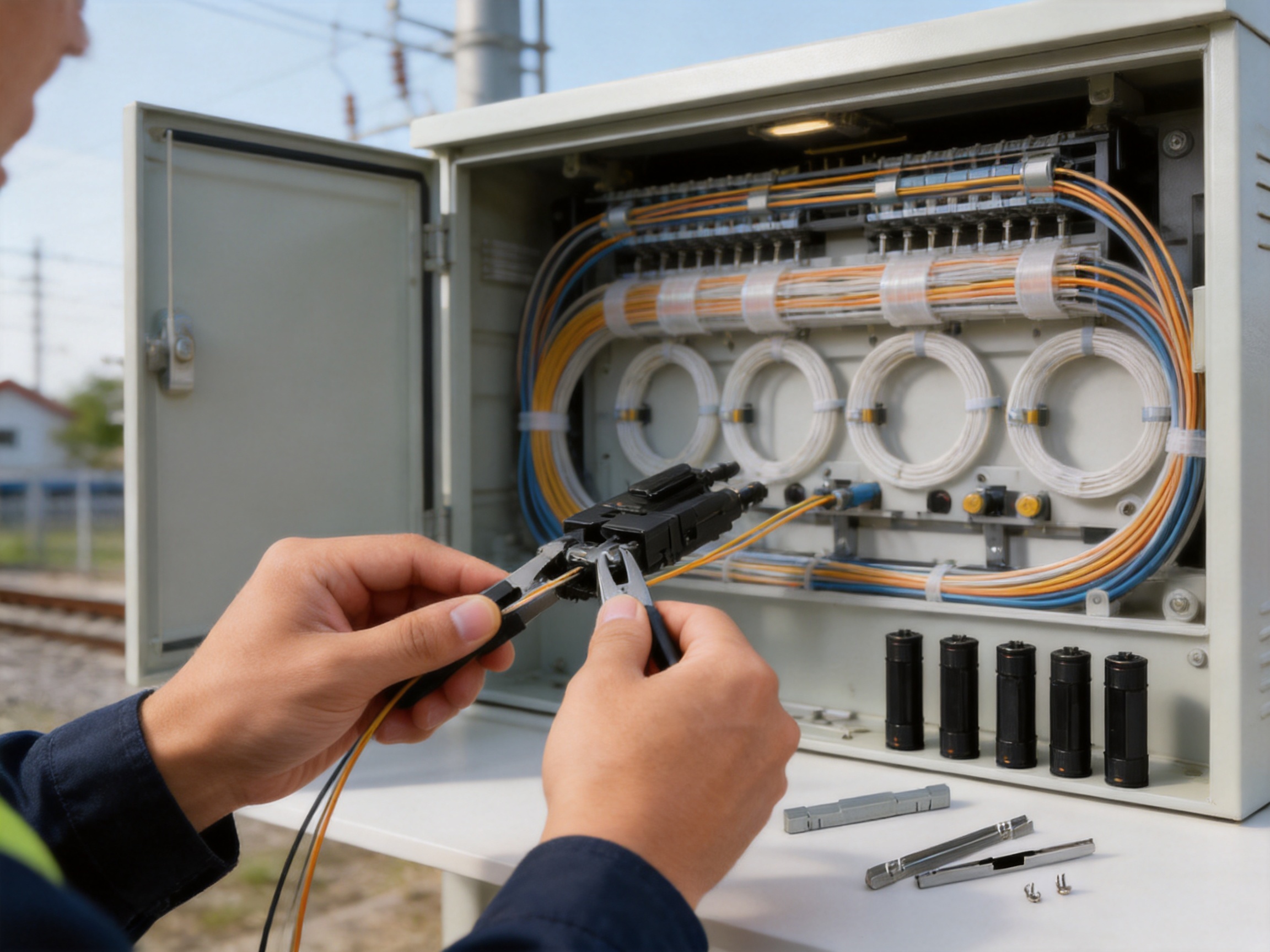
Installation should be performed by trained personnel using the recommended procedure for the selected splice type. The exact sequence may vary according to the product configuration, cable structure, and enclosure design, but several general principles apply.
Preparation of the Work Area
The work area should be clean, organized, and protected from dust, moisture, unnecessary movement, and accidental fiber damage. Optical fibers are sensitive to contamination and bending. A controlled preparation area helps protect the fiber ends and the internal surfaces of the mechanical splice.
Technicians should confirm that the splice type matches the fiber or cable being connected. The required fiber diameters and cable construction should be checked before installation. The enclosure should also provide sufficient space for the splice, fiber routing, bend management, and future maintenance.
Fiber Preparation
The fiber coating or protective layer should be removed according to the applicable preparation procedure. The exposed fiber should be cleaned with an appropriate fiber-cleaning method, and the end face should be prepared carefully. Scratches, dust, residue, or an uneven fiber end can increase insertion loss and reduce consistency.
Fiber routing should avoid sharp bends and excessive tension. Even when the splice itself is correctly assembled, poor routing inside the closure or distribution box can place stress on the connection. Adequate slack and controlled bending are important parts of a reliable installation.
Alignment and Crimping
The prepared fiber ends should be placed into the V-shaped slot so that they remain closely attached to the alignment surfaces. The technician should follow the prescribed positioning method and avoid moving the fibers after they have been aligned.
The mechanical crimping mechanism should then be operated as instructed. Its purpose is to hold the fibers in the aligned position and support good concentricity. Excessive force, incomplete crimping, or incorrect placement may affect performance. A controlled installation procedure helps ensure repeatable results.
Verification and Enclosure Completion
After assembly, the connection should be checked according to the project’s acceptance requirements. Optical testing may include insertion-loss measurement, continuity verification, or other tests defined by the network operator. The enclosure should be closed and secured only after the splice, fiber routing, and protective elements have been inspected.
Documentation should identify the connection location, cable route, fiber number, test result, and maintenance information where required. Clear records make future troubleshooting and network expansion more efficient.
Application in Closures, Distribution Boxes, and Fiber Sockets
Optical Cable Splice Closures
In a splice closure, the mechanical splice can be used to connect or restore fiber paths while keeping the connection organized within the protected housing. The closure should provide appropriate environmental protection and sufficient internal space for fiber routing.
The reopenable structure is particularly useful in closures because these enclosures may be accessed several times during the life of a network. Technicians may need to add a branch, repair a damaged section, or inspect an optical fault. A connection that can be reopened may simplify these tasks.
Optical Cable Distribution Boxes
Distribution boxes often serve as transition points between feeder cables, distribution cables, drop cables, and equipment-side fiber assemblies. They require compact components that can be arranged clearly and maintained without disturbing unrelated connections.
The two available splice types and compatibility with different fiber or cable structures support flexible distribution-box design. The product can help installers adapt the connection method to the physical structure of the incoming and outgoing cables.
Optical Fiber Sockets
Optical fiber sockets are located closer to the service endpoint and may be installed in buildings, rooms, cabinets, or other user-access areas. Space may be limited, and service technicians may need a straightforward way to connect or replace a fiber.
A compact mechanical splice can support the practical requirements of these locations. Its reopenable feature may be useful during customer activation, service troubleshooting, or internal fiber rearrangement, subject to the socket design and installation instructions.
Reliability and Lifecycle Benefits
Reliability in an optical network depends on more than initial optical performance. The connection must continue to perform as the enclosure is handled, as maintenance occurs, and as the network environment changes. The product’s design addresses several aspects of long-term use.
First, the V-slot and mechanical crimping structure support stable fiber positioning. Second, the matching-fluid storage rooms help maintain the optical interface over an extended service period. Third, the reopenable design supports inspection and corrective maintenance. These features work together to support a practical lifecycle strategy.
Low insertion loss is important because losses accumulate throughout an optical link. A connection with excessive loss can reduce available power margin and limit transmission reliability. Consistency is equally important because network planners and installers need predictable performance across many individual connections.
The product is not a substitute for correct network engineering. Optical budgets, enclosure selection, environmental protection, bend radius, cable tension, cleaning procedures, and test requirements must all be considered. However, a well-designed mechanical splice can contribute to a reliable system when it is correctly selected and installed.
Benefits for Contractors and Network Operators
Faster Field Deployment
Mechanical installation can help contractors complete selected connections without setting up a fusion-splicing workstation. This is valuable in confined spaces, temporary work areas, emergency repair locations, and sites where electrical power is difficult to access.
Faster deployment can also improve crew productivity. When the connection procedure is repeatable and the product is easy to handle, technicians can spend less time preparing specialized equipment and more time completing the required fiber routing and testing.
Reduced Maintenance Complexity
The reopenable structure provides a practical maintenance advantage. A technician can access the connection for inspection or adjustment without automatically replacing the complete splice assembly. This may be useful during network expansion, fault isolation, or correction of an installation issue.
Reduced maintenance complexity can be especially valuable for distributed networks. Access points may be located far from central facilities, and each service visit may involve transportation, permits, safety procedures, and coordination with other teams. A serviceable connection can help make these visits more productive.
Support for Customized Projects
Communication infrastructure projects often have different enclosure dimensions, cable arrangements, fiber counts, and operating requirements. A supplier that develops and manufactures its own products while offering integrated customized solutions can support more flexible project coordination.
The manufacturer’s experience with communication cabinets, electronic equipment, and passive optical components allows it to consider the relationship between a splice and the surrounding infrastructure. This system-oriented perspective can be helpful when customers require a coordinated solution rather than an isolated component.
International Supply and Customer Support
The company has a sales network covering more than 20 countries and regions, including the United States, Australia, the United Kingdom, Italy, South Africa, and Ghana. International experience can help support customers with different project environments, purchasing procedures, documentation expectations, and delivery requirements.
The company emphasizes reliable product quality, timely delivery, and long-term strategic partnerships with industry leaders. These priorities are relevant to telecommunications projects, where delivery delays or inconsistent component supply can affect construction schedules and network launch plans.
Selection Considerations
Before selecting a mechanical splice, users should evaluate the fiber or cable type, required enclosure, operating environment, expected optical performance, installation method, and maintenance plan.
The fiber diameter must match the product application. Users should confirm whether they require an optical fiber splice or an optical cable splice. If bow-type optical cables are involved, the number and construction of the cables should be checked against the planned configuration.
The enclosure should protect the splice from conditions that could affect optical performance or mechanical integrity. Depending on the project, this may include moisture, dust, vibration, temperature variation, accidental pulling, and repeated access. The splice alone cannot provide the complete environmental protection of the installation.
Network operators should also define optical acceptance criteria. Insertion loss, consistency, continuity, and any project-specific test requirements should be established before deployment. Technicians should record test results so that future maintenance teams can compare current performance with the original installation condition.
Finally, purchasers should consider supply reliability and technical support. A product may be used in large-scale network construction, so consistent availability, clear installation information, and responsive communication are important factors alongside the product’s physical design.
Recommended Quality and Handling Practices
Keep mechanical splice components in their original protective packaging until they are ready for use. Avoid exposing the product to dust, moisture, impact, or unnecessary temperature extremes during storage and transportation.
Use clean tools and follow appropriate fiber handling procedures. Do not touch prepared fiber ends with bare fingers. Keep protective caps or covers in place whenever the splice is not being assembled.
Do not force fibers into the alignment slot. The fibers should be positioned smoothly and securely. If resistance, contamination, or misalignment is observed, the installation should be paused so that the cause can be identified.
After crimping, inspect the assembly before closing the enclosure. Confirm that the fibers are routed with suitable bend control and that the splice is not exposed to unnecessary tension. If the product is reopened, inspect the fiber ends and matching-fluid condition before reconnecting.
Record the product type, installation point, date, fiber identification, and test results. Clear records support quality assurance, troubleshooting, inventory management, and future network expansion.
Why This Mechanical Splice Is a Practical Competitive Choice
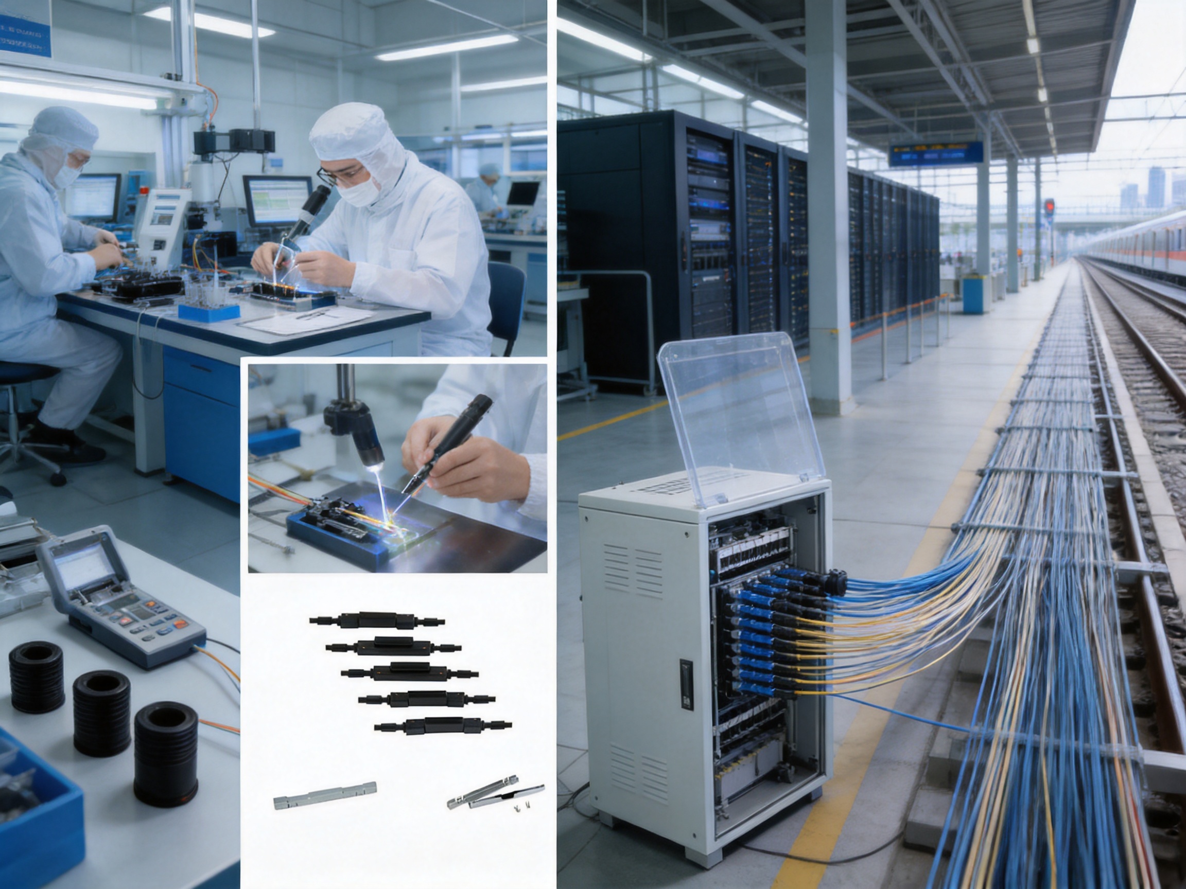
The main competitive value of the Fiber Solution-Mechanical Splice comes from the combination of features rather than from a single isolated function. Many connection products can hold a fiber, and many network technologies can create a fiber joint. The product distinguishes itself by bringing together V-slot alignment, mechanical crimping, low-loss performance, matching-fluid replenishment, compatibility with multiple fiber arrangements, and reopenable operation.
For contractors, this combination supports efficient installation. For network operators, it supports maintainability. For system designers, it provides another option when a permanent fusion joint or conventional connector is not the most suitable solution. For long-term infrastructure owners, the matching-fluid storage and reopenable construction support lifecycle value.
The product also benefits from the manufacturer’s broader telecommunications focus. Experience in communication cabinets, electronic equipment, passive optical components, Ethernet networks, optical communication networks, high-speed railways, and urban rail transit systems creates a practical context for product development and application support.
Its manufacturing and business strengths include long-term industry experience, own-brand product development, integrated customized solutions, international sales coverage, attention to delivery, and an emphasis on long-term partnerships. These capabilities are important because network customers generally need more than a component. They need a dependable supply relationship and a product that fits a complete infrastructure plan.
Q&A
What is a mechanical fiber splice?
A mechanical fiber splice is a passive component that aligns and holds two optical fibers so that light can pass between them. It uses mechanical positioning and securing rather than a permanent fusion process.
Which fibers can this product connect?
The product is designed for Φ0.90 mm and Φ0.25 mm optical fibers. It can also be used for two or three bow-type optical cables according to the applicable splice configuration.
Where can the splice be installed?
Typical applications include optical cable splice closures, optical cable distribution boxes, and optical fiber sockets. It may also be used in other compatible passive optical enclosures when the installation requirements are satisfied.
What is the purpose of the V-shaped slot?
The V-shaped slot guides the fibers into a stable position and helps them remain closely attached to the alignment surfaces. This supports good concentricity and contributes to low insertion loss and consistent performance.
How does mechanical crimping help?
Mechanical crimping holds the aligned fibers in place. It helps prevent unwanted movement after positioning and supports repeatable optical alignment during normal handling and operation.
Why does the product include storage rooms for matching fluid?
The storage rooms supplement matching fluid and direct it toward the splicing point through the product’s internal pumping action. This design supports longer service life and helps maintain the optical interface.
Can the splice be reopened?
Yes. The product can be reopened, which allows inspection, correction, reconnection, or maintenance when required. The recommended procedure should be followed whenever the splice is accessed.
Is a mechanical splice better than fusion splicing in every application?
No connection method is best for every situation. Fusion splicing may be preferred for certain permanent, high-volume, or tightly controlled installations. A mechanical splice is advantageous when field flexibility, rapid deployment, limited equipment, and reopenability are important.
Does the splice eliminate the need for optical testing?
No. Optical testing remains important. Installers should perform the measurements required by the project, which may include insertion loss, continuity, and other acceptance tests.
What should users consider when selecting the product?
Users should confirm the fiber or cable type, diameter, splice configuration, enclosure compatibility, environmental conditions, installation method, optical requirements, and maintenance plan.
What manufacturing strengths support the product?
The manufacturer has experience in communication cabinets, communication electronic equipment, and passive optical components. It develops and manufactures its own products, provides integrated customized solutions, serves international markets, and emphasizes quality, delivery, and long-term customer relationships.
Can the product support railway communication projects?
The product is suitable for applicable passive optical connection requirements within railway and urban rail transit infrastructure. The complete system must still meet the project’s environmental, mechanical, optical, and safety specifications.
Conclusion
The Fiber Solution-Mechanical Splice is designed to provide a practical, serviceable, and consistent method for connecting optical fibers and selected bow-type optical cables. Its V-shaped alignment slot supports accurate positioning, while mechanical crimping helps maintain concentricity. The matching-fluid storage rooms provide replenishment for the splicing point, supporting low insertion loss and extended service life. The reopenable design adds important flexibility for maintenance and network modification.
These characteristics make the product suitable for optical cable splice closures, optical cable distribution boxes, optical fiber sockets, FTTH access networks, Ethernet infrastructure, central equipment rooms, railway communication systems, and urban rail transit applications. Compared with connection methods that depend exclusively on permanent fusion or limited-use mechanical structures, it offers a useful balance of installation convenience, optical consistency, serviceability, and lifecycle value.
The product is further supported by a manufacturer with experience in telecommunications infrastructure, passive optical components, communication cabinets, and electronic equipment. Its own-brand development, manufacturing capabilities, customized solution services, international sales network, and emphasis on reliable quality and timely delivery provide a strong foundation for network customers.
When correctly selected, installed, tested, and protected within a suitable enclosure, the mechanical splice can contribute to dependable optical network construction and long-term infrastructure management. It is a compact component, but its combination of alignment precision, mechanical stability, matching-fluid support, and reopenability makes it an effective solution for many modern fiber deployment scenarios.
References
1. Manufacturer-provided product information for Fiber Solution-Mechanical Splice.
2. Manufacturer-provided company profile and application information for communication cabinets, passive optical components, Ethernet networks, and railway communication infrastructure.
3. International Electrotechnical Commission, optical fiber communication component principles and testing practices.
4. Telecommunications industry guidance on fiber preparation, optical loss measurement, enclosure installation, and network maintenance.
5. General engineering practices for fiber-to-the-home networks, optical distribution systems, railway communication networks, and urban rail transit communications.
Product: Fiber Solution-Mechanical Splice
PREV:High-Density 19-Inch Optical Distribution Frame for Reliable Fiber Network Management
NEXT:Precision Fiber Connectivity for High-Performance Optical Distribution Networks
NEXT:Precision Fiber Connectivity for High-Performance Optical Distribution Networks
Interested in cooperation or have questions?
Related products
-
-
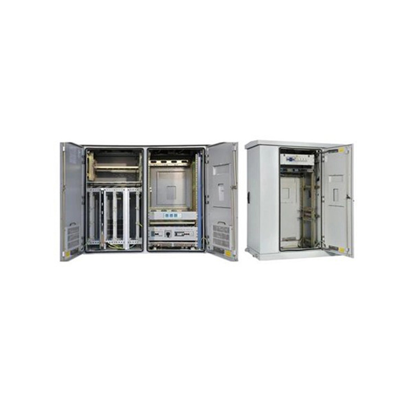
Application:It is used for the fixed network and broadband access, providing physical working environment and security system for the workstation in wired network. Features:•The cabinet is composed of...
See Details -
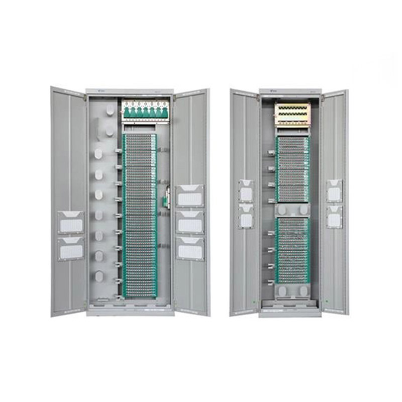
Application ScopeThe GPX129-09T fiber optic distribution frame is used to connect, distribute, and manage fiber optic cables and optical communication equipment. It is suitable for large-capacity fibe...
See Details -
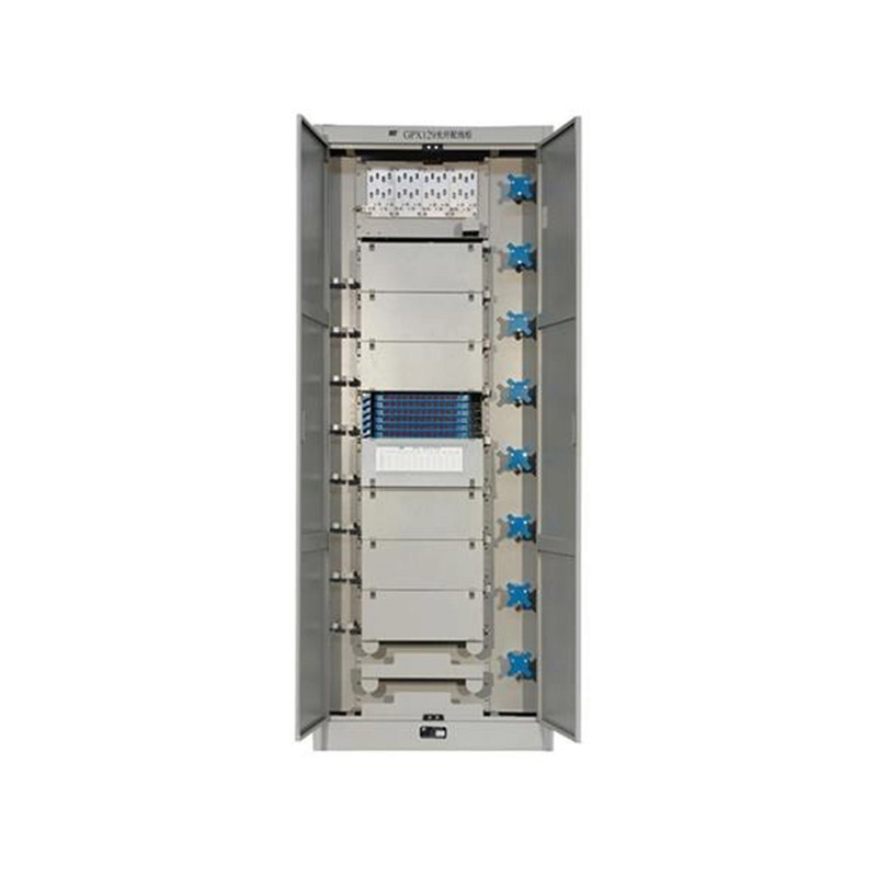
Application ScopeThe GPX129BKC fiber optic distribution frame is used to connect and distribute optical cables to optical communication equipment, and is suitable for large-capacity fiber optic commun...
See Details
Ready to Get started ? Contact Us Now !

Product.
Contact Details.
-
 +86 13958188250
-
 +86 13958188250
-
 [email protected]
-
 AUDIT Email:[email protected]
- Wanma Industrial Park Taihu Yuan Town Lin'an District Hangzhou City China.
QR Code

Copyright © Wanma Technology Co., Ltd. All Rights Reserved.
Privacy
Custom Ethernet Optical Network Railway Transit Equipments Suppliers
