

 English
 Français
 Español
 Português
 عربى






WM-2001-H11 type of It can be used to connect and branch fibers in aerial locations applications. The case body is made from high-intensity engineering plastics and shaped by mould injection under hig...
See DetailsWM-2001-H11 Fiber Optic Splice Closure: High-Capacity Protection for Modern Optical Networks
Content
- 1 Product Overview
- 2 Protection for Demanding Outdoor Environments
- 3 High-Capacity Fiber Management in a Compact Structure
- 4 Mechanical Sealing Without Dependence on Permanent Adhesive Tape
- 5 Compatibility with Different Fiber Cable Designs
- 6 Suitability for Multiple Installation Environments
- 7 Mechanical and Electrical Performance
- 8 Manufacturing Strengths and Process Control
- 9 Advantages Compared with Conventional or Less Versatile Closures
- 10 Installation and Re-Entry Considerations
- 11 Applications in Telecommunications and Transport Infrastructure
- 12 Quality, Supply, and Project Support
- 13 Recommended Selection Checklist
- 14 Long-Term Operational Benefits
- 15 Q&A
- 15.1 What is the primary purpose of the WM-2001-H11?
- 15.2 How many fibers can the closure accommodate?
- 15.3 Can the closure be used with ribbon fiber?
- 15.4 What cable constructions are supported?
- 15.5 Is adhesive sealing tape required?
- 15.6 Can technicians access one splice tray without disturbing the others?
- 15.7 Where can the closure be installed?
- 15.8 What is the working temperature range?
- 15.9 What materials are used in the closure?
- 15.10 How does the closure address lightning-related risks?
- 15.11 Does the product support future network expansion?
- 15.12 What should be verified before ordering?
- 16 Conclusion
- 17 References
- 18 Product: WM-2001-H11 Fiber Optic Splice Closure
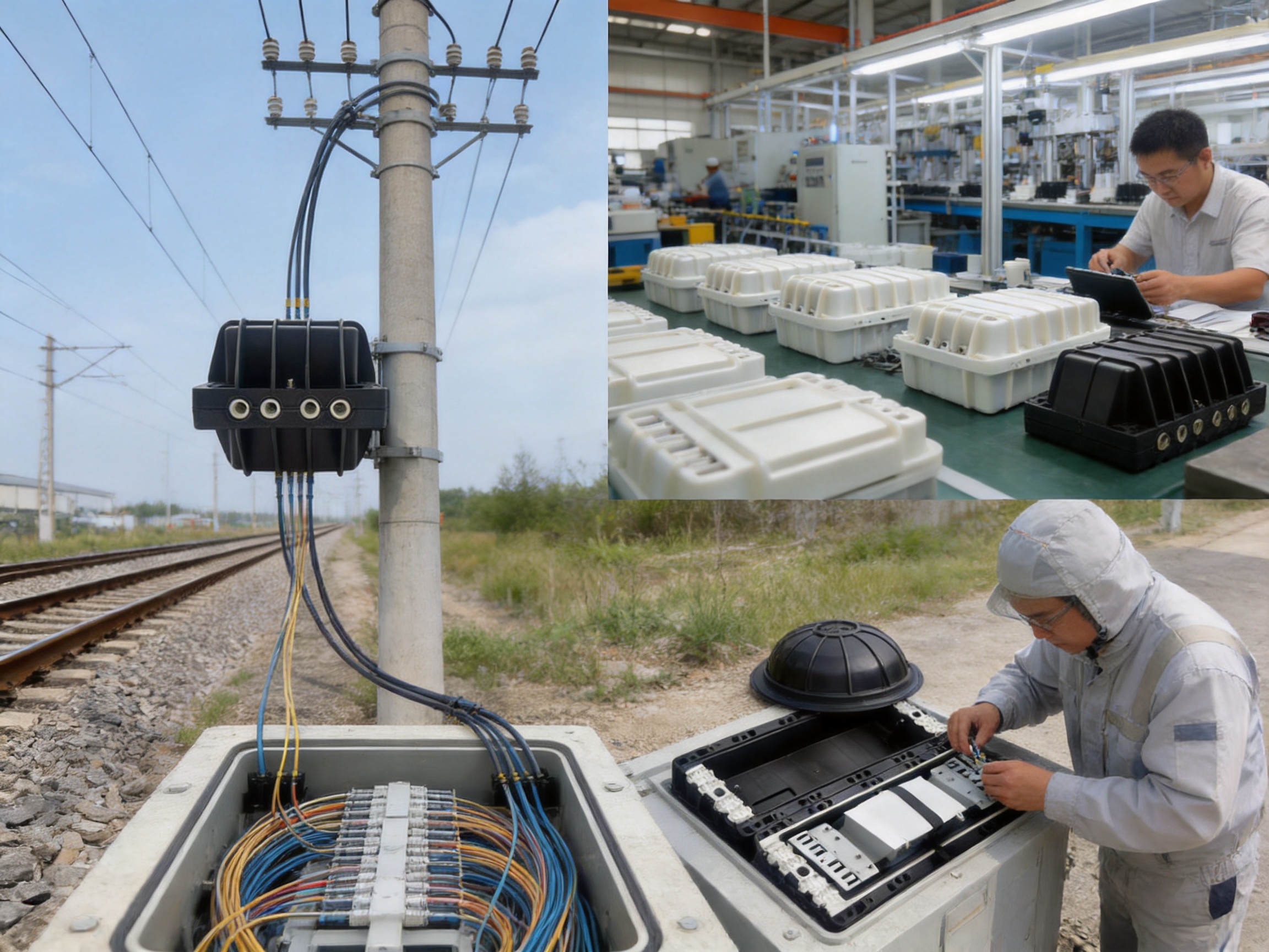
Reliable fiber management is essential to the performance, safety, and long-term maintainability of modern telecommunications infrastructure. As optical networks expand into urban communications systems, railway transit, industrial facilities, broadband access networks, and remote outdoor installations, network operators need splice closures that can protect delicate fiber connections while remaining easy to install, inspect, expand, and repair. The WM-2001-H11 Fiber Optic Splice Closure is designed to meet these requirements through a high-capacity structure, durable engineering materials, mechanical sealing, organized splice-tray management, and compatibility with multiple cable types and installation environments.
Fiber optic splice closures serve as protective enclosures for fiber splices and branching points. They help prevent moisture, dust, mechanical impact, corrosion, ultraviolet exposure, and other environmental hazards from affecting optical connections. In practice, a splice closure must do more than simply surround a splice. It must maintain a controlled bending radius, provide adequate storage for excess fiber, support different cable entry arrangements, resist external forces, and allow technicians to access individual trays without disturbing neighboring connections. These requirements become especially important in aerial locations, ducts, direct-buried installations, handholes, and manholes, where environmental and maintenance conditions can vary considerably.
The WM-2001-H11 addresses these challenges with a dome-and-base construction made from modified polypropylene reinforced with glass fiber, ABS splice trays, stainless-steel internal and fixing components, and a mechanical sealing structure supported by an O-ring system. Its configuration accommodates up to 12 splice trays, with each tray supporting up to 24 fibers, for a total capacity of 288 fibers. This combination of capacity, protection, and serviceability makes the closure suitable for network expansion projects as well as repair, branch, tap-off, and expressed applications.
Product Overview
The WM-2001-H11 is an outdoor fiber optic splice closure intended for connecting and branching optical fibers. Its enclosure protects fiber splices from environmental contamination and mechanical stress while providing space for fiber routing and storage. The unit has a compact external form compared with its fiber capacity, measuring approximately 480 by 190 by 180 millimeters. The cable entry ports have a nominal diameter of 14 millimeters, allowing the closure to accommodate compatible optical cables used in access, distribution, and communication networks.
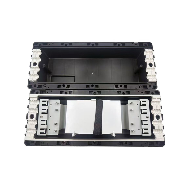
The closure is designed around a dome-and-base structure. The base supports the cable entry ports and internal splice-management components, while the dome provides a protective cover around the splice trays and stored fibers. A clamp and O-ring system joins and seals the base and dome. Cable entry ports are sealed with rubber components, and the product may use mechanical and heat-shrinkable sealing methods depending on the installation configuration and cable arrangement.
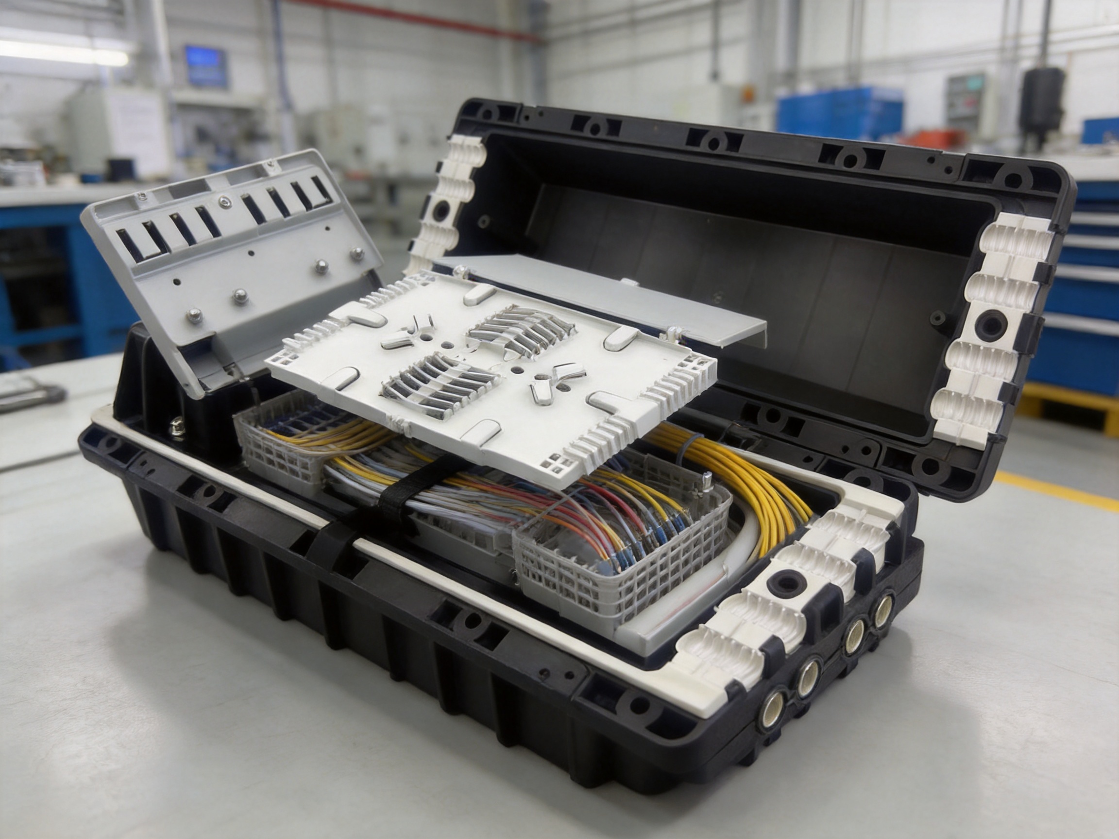
The internal layout is intended to make fiber work more organized and predictable. Splice trays are hinged, allowing technicians to reach a particular tray without removing or disturbing every tray above it. Excess fiber can be retained in dedicated storage baskets or storage areas, helping prevent sharp bends, tangles, and unnecessary stress on the optical cable. The specified splice-tray routing radius supports low optical loss and helps protect fibers during installation and future maintenance.
| Item | Specification |
| Model | WM-2001-H11 |
| Primary function | Fiber connection, branching, repair, tap-off, and splice protection |
| Number of splice trays | 12 |
| Capacity per tray | 24 fibers |
| Total fiber capacity | 288 fibers |
| Approximate dimensions | 480 × 190 × 180 millimeters |
| Entry port diameter | 14 millimeters |
| Dome and base material | Modified polypropylene with glass-fiber reinforcement |
| Splice tray material | ABS |
| Sealing method | Mechanical and heat-shrinkable sealing methods |
| Working temperature | -40°C to +70°C |
| Atmospheric pressure range | 70 to 150 kilopascals |
| Axial tension performance | More than 2,000 newtons for one minute |
| Insulation resistance | More than 2 × 10⁴ megohms |
| Voltage strength | 15 kilovolts for one minute without arc-over or breakdown |
| Water-pressure performance | 50 meters for 72 hours, according to the stated test condition |
Protection for Demanding Outdoor Environments
Optical splice points are vulnerable to environmental exposure because the fiber itself is sensitive to excessive bending, contamination, moisture intrusion, and mechanical strain. A closure installed outdoors must maintain protection throughout seasonal temperature changes and repeated maintenance cycles. The WM-2001-H11 is specified for operation from -40°C to +70°C, covering a broad range of cold and hot conditions encountered in outdoor telecommunications infrastructure.
The enclosure body is formed from high-intensity engineering plastic through high-pressure injection molding. The stated material system includes modified polypropylene with glass-fiber reinforcement. This type of material structure is useful where a product must combine low weight with rigidity, impact resistance, dimensional stability, and resistance to environmental aging. Glass-fiber reinforcement can improve mechanical strength and help the enclosure retain its shape when exposed to temperature changes, cable loading, and handling during installation.
The product material is also described as having anti-ultraviolet and corrosion-resistance characteristics. These properties are valuable in aerial installations, where the closure may be exposed to direct sunlight, rain, wind, airborne pollutants, and changing humidity for extended periods. Unlike metallic enclosures that may require additional surface protection against corrosion, an appropriately formulated engineering-plastic enclosure can reduce corrosion-related maintenance concerns while also simplifying handling.
The material is further described as having anti-thunderstruck characteristics, supported by an earthing device intended to protect the closure from lightning-related damage. Outdoor optical networks can be exposed to electrical activity even though optical fiber itself does not conduct electrical signals. Metallic strength members, cable components, mounting hardware, and nearby infrastructure may still create grounding and bonding requirements. The inclusion of an earthing arrangement supports more systematic installation practices, especially for aerial routes and exposed communications infrastructure.
Mechanical protection is complemented by sealing performance. The base and dome use a clamp and O-ring system, while cable entries are sealed with rubber components. This arrangement creates a serviceable enclosure that can be opened and resealed without relying exclusively on permanent adhesive compounds. The stated water-pressure performance is 50 meters for 72 hours under the specified test condition, demonstrating the design’s intended resistance to water penetration in demanding installations.
WM-2001-H11 Fiber Optic Splice Closure
High-Capacity Fiber Management in a Compact Structure
A major advantage of the WM-2001-H11 is the relationship between its compact dimensions and its total fiber capacity. The closure supports 12 trays, with a rated capacity of 24 fibers per tray, providing space for up to 288 fibers. This capacity can help reduce the number of separate closures required in high-density distribution sections and can simplify planning where multiple cables converge at a branch or access point.
High capacity is beneficial only when the internal organization is practical. Crowded splice enclosures can create installation problems if fibers are forced into tight bends or if technicians must remove several layers of components to reach a single splice. The WM-2001-H11 uses hinged splice trays to improve accessibility. A technician can open or move the required tray to inspect or service a splice without disturbing all other trays. This feature can reduce the risk of accidental fiber movement and shorten maintenance time.
Excess fiber storage is another important part of fiber management. Fiber slack must be stored in a controlled manner so that it is not compressed, kinked, or exposed to unnecessary tensile force. The closure provides storage baskets or storage areas for excess fibers. Proper storage helps maintain a suitable routing radius and makes later re-entry or repair more efficient. It also gives technicians a clear path for identifying individual fibers and following them from the cable entry point to the splice tray.
The product information identifies an optical fiber routing radius of at least 40 millimeters in the product description and a 30-millimeter taking-in radius in the technical parameter section. Because the stated figures differ, installers should confirm the applicable radius for the specific tray configuration and installation method before deployment. In all cases, the practical purpose is the same: the internal design is intended to prevent excessive bending and support low optical loss. Following the manufacturer’s installation guidance and the cable supplier’s minimum bend-radius requirements remains essential.
Organized tray management can also improve documentation. In a large network, technicians may need to record cable identifiers, splice positions, branch routes, and service assignments. Hinged trays and clearly controlled fiber routing make it easier to inspect the physical layout and match it with network records. This is particularly useful in railway communications, urban transit systems, broadband distribution networks, and other infrastructure where maintenance windows may be short.
Mechanical Sealing Without Dependence on Permanent Adhesive Tape
Traditional closure designs may depend heavily on sealing tapes, mastics, or permanent adhesives. Although these materials can be effective when correctly applied, they may require careful preparation, clean surfaces, correct tension, and consistent installation technique. They can also make re-entry more difficult, especially when the closure must be opened years after its original installation.
The WM-2001-H11 uses a fully mechanical sealing concept for the main enclosure, combined with rubber cable seals and, where applicable, heat-shrinkable sealing components. The clamp and O-ring system is designed to press the dome and base together in a controlled manner. This approach can make installation more repeatable and can simplify re-entry when technicians need to add, replace, or test fibers.
Eliminating the need for additional sealing adhesive tape offers several operational advantages. Installation can be faster because technicians do not need to wrap and prepare multiple layers of tape around the main housing. The closure is less dependent on the appearance and consistency of a manual tape application. Re-entry can also be cleaner, with fewer adhesive residues and less time spent removing old sealing materials.
Mechanical sealing does not eliminate the need for careful installation. O-rings must be clean, correctly positioned, and free from cuts or deformation. Clamps must be tightened according to the specified procedure, and cable entry seals must match the cable diameter and configuration. Heat-shrinkable components, when used, require proper heating equipment and temperature control. The advantage of the design is that these steps are structured and repeatable rather than relying primarily on improvised adhesive wrapping.
Compatibility with Different Fiber Cable Designs
Network construction projects use many different fiber cable types. A splice closure that supports only one cable design can increase procurement complexity and limit future network changes. The WM-2001-H11 is described as compatible with single-fiber and ribbon cable types, as well as loose-tube, central-core, slotted-core, and modular cable constructions.
This compatibility supports a wide range of network applications. Single-fiber cables may be used in access networks, repair sections, or low-count distribution routes. Ribbon cables are common where high fiber counts must be managed efficiently. Loose-tube and central-core designs may be selected according to mechanical protection, water-blocking, installation method, or network architecture. Slotted-core and modular constructions may be used where the cable must support particular installation or fiber-access requirements.
Cable compatibility must always be evaluated together with cable diameter, strength-member arrangement, entry-port dimensions, and the closure’s cable fixation components. The stated entry port diameter is 14 millimeters, so the installer should confirm that the selected cable, seal, and strain-relief arrangement are suitable. The closure should also be installed using the correct cable preparation length and strength-member bonding procedure.
Broad cable compatibility creates an advantage over narrowly specialized closures. It can allow one closure platform to be used across several phases of a network build. Operators may standardize training, spare parts, installation tools, and maintenance procedures. Contractors can also reduce the number of closure types carried to the field, provided that cable and port compatibility has been verified in advance.
Suitability for Multiple Installation Environments
The WM-2001-H11 is designed for aerial locations, ducted applications, direct burial, handholes, and manholes. These installation environments present different mechanical and environmental challenges, yet a versatile closure can support consistent network design across them.
Aerial Applications
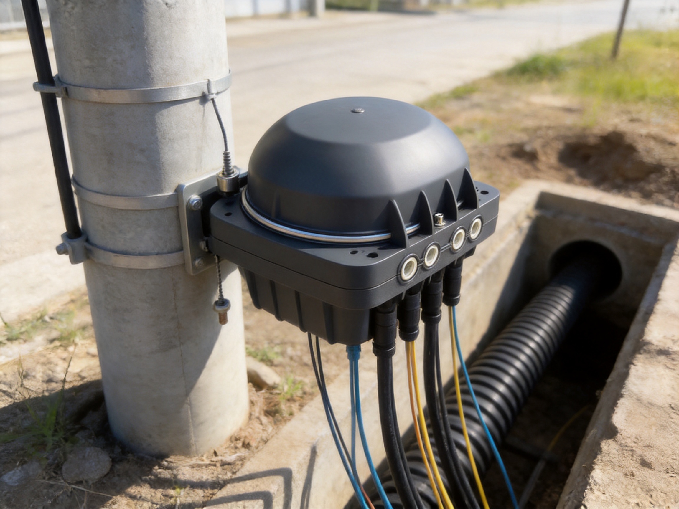
In aerial networks, the closure may be mounted on a pole, messenger wire, or other support structure. It must withstand wind movement, temperature cycling, rain, sunlight, and potential vibration. The high-strength plastic housing can reduce the weight placed on the support system compared with a similarly sized metal enclosure. The integrated earthing device and mechanical sealing system further support outdoor deployment, although the installer must provide appropriate mounting, bonding, and cable strain relief.
Ducted Applications
Ducted installations can place the closure in confined spaces where access is limited. A compact structure and organized hinged trays help technicians work more efficiently when the available working area is restricted. The closure’s mechanical sealing system can also be useful in duct environments because it reduces reliance on external adhesive tape and provides a controlled enclosure interface.
Direct-Buried Installations
Direct burial exposes a closure to soil pressure, moisture, temperature variation, and possible movement caused by ground settlement. The stated water-pressure performance and durable engineering-plastic construction are relevant to this type of deployment. Direct-buried installation still requires proper excavation, bedding, drainage consideration, cable routing, and protection from excessive loading. A closure should not be treated as a substitute for correct civil construction practices.
Handholes and Manholes
Handholes and manholes are common locations for branch connections and repair points. They may experience condensation, standing water, dirt, accidental impact, and repeated access by maintenance teams. The WM-2001-H11’s sealed housing and serviceable tray arrangement are suited to these conditions when the closure is correctly installed and the surrounding chamber is managed appropriately.
Using one closure design across several environments can simplify network engineering. The same basic product can be included in aerial, underground, and chamber-based plans, while the mounting and cable-entry details are adapted to each location. This can make inventory control, technician training, and maintenance documentation more consistent.
Mechanical and Electrical Performance
The stated technical parameters indicate that the closure is intended to withstand significant mechanical and environmental stresses. Its axial tension performance is specified as greater than 2,000 newtons for one minute. This characteristic is relevant to cable fixation and the ability of the closure assembly to resist pulling forces during installation or service conditions.
The product also lists stretching resistance of 2,500 newtons per 10 square centimeters for one minute. This type of test value provides an indication of the enclosure’s ability to tolerate a defined mechanical load over a specified area. Installers should distinguish between the enclosure’s test performance and the allowable tension of the optical cable itself. Cable loading must be managed using the cable manufacturer’s specifications and suitable strain-relief hardware.
Insulation resistance is specified as greater than 2 × 10⁴ megohms. The voltage-strength test is listed as 15 kilovolts for one minute, without arc-over or breakdown. These values indicate attention to electrical insulation and protection, which can be important in outdoor installations containing metallic cable elements, grounding hardware, or nearby electrical infrastructure.
Although the transmission medium is nonconductive glass fiber, a complete fiber network installation may include metallic strength members, armor, messenger wires, grounding conductors, and mounting structures. A closure’s insulation and earthing provisions therefore contribute to overall site safety and equipment protection. Electrical tests and grounding work should be performed by qualified personnel using the applicable local safety procedures.
Atmospheric pressure performance is specified from 70 to 150 kilopascals. This range covers common pressure variations associated with altitude and weather conditions. It supports the product’s intended use across different outdoor and infrastructure environments, subject to the installation limitations established by the project design.
Manufacturing Strengths and Process Control
The performance of a fiber optic splice closure depends heavily on manufacturing consistency. The housing must maintain dimensional accuracy so that the dome, base, clamp, O-ring, and cable-entry components fit together correctly. Splice trays must be formed with stable geometry so that fibers can be routed without obstruction. Internal fixing parts must remain secure during installation and service. These requirements make production process control an important part of product quality.
The closure body is shaped by high-pressure injection molding. This manufacturing method is well suited to producing repeatable engineering-plastic components with integrated shapes, mounting features, and structural details. During injection molding, prepared polymer material is heated and injected into a precision mold under controlled pressure. Once the material fills the cavity and cools, the formed component can be removed and inspected.
High-pressure injection molding offers several benefits for this type of product. It supports consistent reproduction of the dome and base geometry, reduces dependence on manual fabrication, and allows complex contours to be formed efficiently. Repeatable molding is especially important for sealing surfaces, clamp interfaces, cable-entry zones, and tray-support features. If these areas vary excessively from one unit to another, sealing reliability and assembly quality can be affected.
The use of modified polypropylene with glass-fiber reinforcement reflects a material-selection strategy focused on strength, weight, and environmental resistance. Material preparation, temperature control, mold filling, cooling, and demolding must be managed carefully to minimize warpage, voids, surface defects, and dimensional variation. Production teams can use process monitoring and inspection procedures to verify that molded parts meet the required shape and fit.
ABS is used for the splice trays. ABS is suitable for formed internal components because it combines rigidity, impact resistance, and practical manufacturability. Tray dimensions and hinge features must be controlled so that trays move smoothly and remain aligned inside the enclosure. The tray structure must also provide enough support for fiber routing, splice holders, and slack storage without creating sharp edges that could damage fiber coatings.
Stainless steel is used for internal and fixing parts. This choice helps improve resistance to corrosion and supports long-term mechanical stability in humid or contaminated environments. Stainless-steel hardware can also be advantageous during repeated maintenance because screws, brackets, and fixing elements are less vulnerable to corrosion-related seizure than ordinary untreated steel.
Advanced manufacturing strength is not limited to the molding machine. It also includes product design, material selection, mold engineering, assembly control, inspection, packaging, and technical feedback from field applications. A manufacturer with experience in communication cabinets, electronic equipment, passive optical components, and network infrastructure can apply cross-product knowledge to the development and production of splice closures. This broader manufacturing background supports more coordinated design decisions involving mechanical protection, optical management, grounding, and deployment conditions.
Production for communications infrastructure also benefits from scalable manufacturing. A standardized closure design can be produced in consistent batches while retaining the flexibility needed for customized network projects. A strong manufacturing organization can coordinate engineering, procurement, production, quality assurance, and delivery, helping customers receive products according to project schedules rather than treating each order as an isolated transaction.
Advantages Compared with Conventional or Less Versatile Closures
Higher Fiber Density
With capacity for 288 fibers, the WM-2001-H11 can support high-density splice requirements in a relatively compact housing. A lower-capacity closure may require several units for the same network section, increasing installation labor, mounting requirements, and maintenance points. High density can be particularly valuable at distribution nodes, branch locations, and areas where multiple feeder and distribution cables meet.
Improved Service Accessibility
Hinged splice trays provide access to individual trays without disturbing all other trays. In a conventional stacked arrangement, reaching a lower tray may require lifting or removing several upper trays. That process can increase the chance of fiber movement or accidental damage. The hinged design supports more controlled maintenance and can reduce the time required for troubleshooting or expansion.
Reduced Dependence on Adhesive Sealing Materials
The mechanical sealing design avoids the need for additional sealing adhesive tape for the main closure interface. This can make installation cleaner and more repeatable. It also supports easier re-entry, an important advantage for networks that may undergo upgrades, branch additions, or fault repairs throughout their service life.
Broad Cable and Application Compatibility
Support for single-fiber and ribbon cables, together with loose-tube, central-core, slotted-core, and modular constructions, provides greater flexibility than a closure designed around one cable format. Compatibility with aerial, ducted, buried, handhole, and manhole environments can also reduce the need to qualify different closure platforms for every section of a network.
Durable Nonmetallic Housing
The modified polypropylene and glass-fiber material system provides a balance of structural strength and manageable weight. Anti-ultraviolet and corrosion-resistance characteristics are useful for long-term outdoor service. Compared with some conventional metallic housings, the nonmetallic body can reduce corrosion concerns and make field handling easier.
Controlled Fiber Bending
Fiber-routing features and storage areas help maintain an appropriate bend radius. This supports low optical loss and reduces the risk of microbending or macrobending caused by careless slack storage. The benefit is not only immediate optical performance but also greater stability after repeated access and environmental changes.
Lightning-Protection Consideration
The earthing device gives installers a defined feature for handling grounding requirements associated with outdoor deployment. This is preferable to treating grounding as an afterthought, particularly in aerial routes and sites with metallic cable components or exposure to lightning activity.
Installation and Re-Entry Considerations
A successful installation begins with selecting a suitable location. The closure should be positioned where it can be securely supported, protected from unnecessary impact, and accessed by technicians. The cable route should avoid sharp changes in direction near the entry ports. Adequate working space should be available for cable preparation, fiber splicing, sealing, and future maintenance.
Before opening the closure, installers should verify the cable type, outer diameter, fiber count, strength-member design, and required splice arrangement. The correct cable entry seals, heat-shrinkable components, splice holders, grounding hardware, and mounting accessories should be prepared in advance. Clean working conditions are important because dust, moisture, and debris can affect splice performance and sealing surfaces.
Fiber preparation should follow the cable manufacturer’s recommended stripping and buffer-removal procedures. Strength members should be fixed securely so that tensile loads are not transferred to the fibers or splice holders. Fibers should be routed through the storage areas with smooth bends and sufficient slack. No fiber should be forced into a tray or compressed beneath a cover.
When assembling the dome and base, the O-ring should be inspected for contamination, cuts, twisting, or displacement. The mating surfaces should be clean, and the clamp should be closed evenly. Cable ports should be sealed using the correct rubber components and heat-shrinkable parts where required. After installation, the closure should be inspected for proper mechanical engagement and checked according to the project’s optical, sealing, and grounding procedures.
Re-entry should be planned as part of the original installation. A closure that is easy to open but difficult to restore may create problems later. The WM-2001-H11’s mechanical sealing approach is intended to support re-entry without requiring new adhesive tape at the main housing interface. However, any removed or damaged O-ring, rubber cable seal, or heat-shrinkable component should be replaced as necessary. After re-entry, the closure must be resealed and tested according to the applicable maintenance procedure.
Applications in Telecommunications and Transport Infrastructure
Fiber optic networks are used in broadband access, enterprise communications, mobile backhaul, industrial control, security systems, railway signaling support, passenger information systems, and urban transit communications. Each application requires stable optical connectivity and manageable maintenance practices.
FTTH and Broadband Distribution
In fiber-to-the-home and broadband modernization projects, closures may be installed at feeder-to-distribution transition points, neighborhood branches, or repair locations. The WM-2001-H11’s capacity can support a significant number of fiber connections, while its tray organization helps separate different subscriber or distribution groups. The ability to add or service individual trays is useful when network growth occurs in phases.
Ethernet and Optical Communication Networks
Ethernet networks increasingly rely on fiber links for distance, bandwidth, electromagnetic immunity, and reliability. A splice closure can protect physical-layer connections between central equipment rooms, distribution cabinets, outdoor pathways, and remote nodes. Its broad environmental compatibility makes it suitable for sections where cables move between indoor and outdoor infrastructure.
Railway and Urban Rail Transit
Railway and urban transit systems require communications infrastructure that can operate along long routes and through challenging environments. Fiber closures may be placed near stations, along trackside routes, in service chambers, or at communication cabinets. The WM-2001-H11’s resistance to temperature variation, moisture, mechanical loading, and ultraviolet exposure supports these applications when the closure is installed according to railway and site-specific requirements.
Industrial and Utility Networks
Industrial sites and utility corridors often contain long outdoor cable routes, high electromagnetic activity, vibration, and difficult access conditions. Fiber is valuable in these environments because it is resistant to electromagnetic interference, but splice points still require mechanical and environmental protection. The closure’s grounding provision, stainless-steel internal hardware, and serviceable tray layout can help support reliable field deployment.
Network Repair and Restoration
Accidental cable damage, construction activity, weather events, and equipment upgrades may require emergency or planned repairs. A closure that can be opened and resealed mechanically gives technicians a practical platform for restoration work. Adequate capacity also allows spare fiber and future branch connections to be managed without immediately installing another enclosure.
Quality, Supply, and Project Support
Product quality in optical infrastructure is closely connected to supply reliability. Network operators and contractors need products that remain consistent across orders, arrive in suitable packaging, and can be supported with technical information. A manufacturer experienced in communication equipment and passive optical components can offer more than a single enclosure; it can provide a coordinated product portfolio for cabinets, optical distribution, network protection, and related infrastructure.
Manufacturing experience since 1997 demonstrates a long operating history in communications-related products. Experience across communication cabinets, electronic equipment, and passive optical components can contribute to practical product development because these product categories share requirements involving enclosure design, cable organization, thermal and environmental considerations, assembly quality, and field serviceability.
International sales coverage also provides exposure to different project specifications, climate conditions, installation practices, and customer expectations. Experience serving customers across North America, Europe, Africa, Australia, and other regions can help a manufacturer understand the importance of documentation, packaging, delivery coordination, and adaptable product configurations.
For large infrastructure projects, customers may also require customized solutions. Customization can involve cable-entry arrangements, mounting options, labeling, fiber-count configurations, packaging, or integration with related network products. A manufacturer that develops and markets its own products while providing integrated solutions is positioned to coordinate these requirements more efficiently than a purely trading-based supplier.
Packaging is another practical consideration. The stated packing configuration is two pieces per outer box, with an approximate outer-box size of 500 by 370 by 210 millimeters and a packed weight of approximately 8.6 to 9.0 kilograms. Clear packing information helps logistics teams plan storage, transportation, lifting, and site delivery. It also helps contractors estimate the number of units that can be moved to an installation area during each work shift.
Recommended Selection Checklist
Before specifying the WM-2001-H11 for a project, network planners should evaluate the following factors:
First, confirm the required fiber count and splice arrangement. The rated total capacity is 288 fibers based on 12 trays with 24 fibers per tray. The actual usable capacity may depend on splice-holder type, fiber cable construction, slack-storage requirements, and the selected protection sleeves.
Second, verify cable diameter and entry-port compatibility. The listed entry port diameter is 14 millimeters. Cable seals and strain-relief components must be selected to match the actual cable construction and project installation method.
Third, confirm the installation environment. The closure is identified for aerial, ducted, direct-buried, handhole, and manhole applications, but each location requires suitable support, drainage, mechanical protection, and access planning.
Fourth, review the cable’s minimum bend radius and compare it with the closure’s internal routing design. The product information contains both a 40-millimeter and a 30-millimeter radius reference, so the applicable value should be confirmed with the supplier before final engineering.
Fifth, plan grounding and bonding. Where metallic cable elements, messenger wires, armor, or nearby electrical systems are present, the earthing device should be connected according to local regulations and the project’s grounding design.
Sixth, check the temperature, water, mechanical, and electrical requirements of the site. The listed performance parameters provide useful design references, but the complete project specification may require additional testing or certification.
Seventh, consider future expansion. The high tray count and organized storage areas can provide room for additional splices or branch connections, but unused capacity should be reserved and documented rather than filled without a planned fiber-management strategy.
Long-Term Operational Benefits
A splice closure should be evaluated over its entire service life rather than only by its initial purchase price. Installation labor, maintenance access, fault-repair time, spare-parts requirements, and network expansion all influence the total cost of ownership. The WM-2001-H11’s design addresses several of these factors.
High fiber capacity can lower the number of enclosures required in a dense network area. Fewer closures may mean fewer mounting points, fewer cable transitions, fewer inspection locations, and less documentation complexity. The compact design can also help when installation space is limited.
Hinged trays can reduce maintenance disruption. A technician can access the relevant tray while leaving other splices arranged in place. This may decrease the likelihood of disturbing active fibers and can shorten the duration of a service window.
Mechanical sealing can simplify re-entry and reduce consumable requirements. When a closure is opened for an upgrade or repair, technicians can focus on the optical work instead of removing large amounts of old adhesive tape. Correctly maintained mechanical sealing can also support more consistent restoration after service.
Durable materials and stainless-steel internal parts can reduce degradation caused by ultraviolet exposure, corrosion, and repeated handling. Although no enclosure is maintenance-free, a robust housing can contribute to longer service intervals and more predictable performance.
Standardization is another operational benefit. If a network operator uses the same closure model across multiple environments and cable types, technicians can become familiar with one internal layout, one tray-access method, and one general sealing process. Standardization can simplify training and reduce installation errors.
Q&A
What is the primary purpose of the WM-2001-H11?
The primary purpose is to protect fiber optic splices while allowing optical fibers to be connected, branched, stored, and maintained. It is designed for applications such as tap-off, expressed splicing, branching, repair, and distribution.
How many fibers can the closure accommodate?
The stated configuration includes 12 splice trays, with a capacity of 24 fibers per tray. The total rated capacity is therefore 288 fibers. The practical capacity of a particular installation may vary according to splice-protection components, cable construction, and fiber-routing requirements.
Can the closure be used with ribbon fiber?
Yes. The product information identifies compatibility with both single-fiber and ribbon cable types. The installer should still verify the appropriate splice tray, holder, and fiber-management accessories for the selected ribbon configuration.
What cable constructions are supported?
The closure is described as compatible with loose-tube, central-core, slotted-core, and modular cable constructions. Cable diameter, strength-member arrangement, and entry-seal compatibility should be confirmed before installation.
Is adhesive sealing tape required?
The main enclosure uses a mechanical sealing structure, so additional sealing adhesive tape is not required for the primary dome-and-base interface. Rubber cable seals and heat-shrinkable sealing components may be used at cable entry points, depending on the installation arrangement.
Can technicians access one splice tray without disturbing the others?
Yes. The splice trays are hinged to allow access to an individual tray without requiring all trays to be removed or rearranged. This design supports more efficient inspection, testing, expansion, and repair.
Where can the closure be installed?
The listed applications include aerial locations, ducts, direct-buried installations, handholes, and manholes. The correct mounting, cable fixation, drainage, and environmental protection procedures must be applied for each location.
What is the working temperature range?
The specified working temperature range is -40°C to +70°C. Project engineers should compare this range with the expected minimum and maximum temperatures at the installation site.
What materials are used in the closure?
The dome and base are made from modified polypropylene with glass-fiber reinforcement, while the splice trays are made from ABS. Internal and fixing parts are made from stainless steel. These materials are selected to balance strength, weight, dimensional stability, corrosion resistance, and manufacturability.
The closure includes an earthing device intended to help protect against lightning-related damage. The grounding connection must be integrated into the site’s approved earthing and bonding system by qualified personnel.
Does the product support future network expansion?
Its 12-tray, 288-fiber configuration provides substantial capacity for current connections and planned growth. Future expansion should be designed in advance, with spare fibers, tray positions, and slack-storage areas properly reserved and documented.
What should be verified before ordering?
Customers should verify fiber count, splice type, cable construction, cable diameter, entry-port requirements, installation environment, bend-radius requirements, mounting method, grounding needs, and any project-specific certification or testing requirements. The different bend-radius figures stated in the product information should also be clarified before final approval.
Conclusion
The WM-2001-H11 Fiber Optic Splice Closure is a high-capacity, serviceable, and versatile solution for protecting optical fiber connections in demanding network environments. Its 12 hinged splice trays provide space for up to 288 fibers, while dedicated storage areas support orderly fiber management and low optical loss. The dome-and-base housing, made from glass-fiber-reinforced modified polypropylene, combines structural strength with reduced weight and resistance to ultraviolet exposure and corrosion.
Its mechanical clamp-and-O-ring sealing system provides a practical alternative to closure designs that depend heavily on adhesive tape. Rubber cable seals and heat-shrinkable components support cable-entry protection, while stainless-steel internal hardware contributes to long-term durability. Compatibility with single-fiber, ribbon, loose-tube, central-core, slotted-core, and modular cable designs gives the product flexibility across different network architectures.
The closure is also suitable for aerial, ducted, direct-buried, handhole, and manhole installations. Its temperature, mechanical, insulation, voltage-strength, and water-pressure specifications provide useful performance references for project planning. Combined with high-pressure injection molding, material control, standardized assembly, and experience in communications equipment manufacturing, these features position the product as a practical choice for broadband modernization, Ethernet optical networks, railway communications, urban transit systems, industrial networks, and repair infrastructure.
For network operators and contractors, the most important value is not simply the number of fibers contained in the enclosure. It is the combination of capacity, protection, accessibility, sealing, compatibility, and manufacturing consistency. When correctly selected and installed, the WM-2001-H11 can help create optical networks that are easier to expand, faster to maintain, and better prepared for long-term service.
References
1. Product technical specification for the WM-2001-H11 Fiber Optic Splice Closure.
2. Manufacturer-provided product information covering materials, capacity, sealing, installation environments, and mechanical performance.
3. General principles of fiber optic cable preparation, splice protection, bend-radius control, and optical-fiber maintenance.
4. Engineering practices for outdoor telecommunications enclosures and passive optical network infrastructure.
5. General guidance on grounding, bonding, environmental protection, and maintenance of communications installations.
Product: WM-2001-H11 Fiber Optic Splice Closure
PREV:Intelligent Sorting and Packaging Stations for Traceable Medical Fabric Management
NEXT:288-Core SMC Fiber Optic Cross-Connection Cabinet for Outdoor Network Infrastructure
NEXT:288-Core SMC Fiber Optic Cross-Connection Cabinet for Outdoor Network Infrastructure
Interested in cooperation or have questions?
Related products
-
-
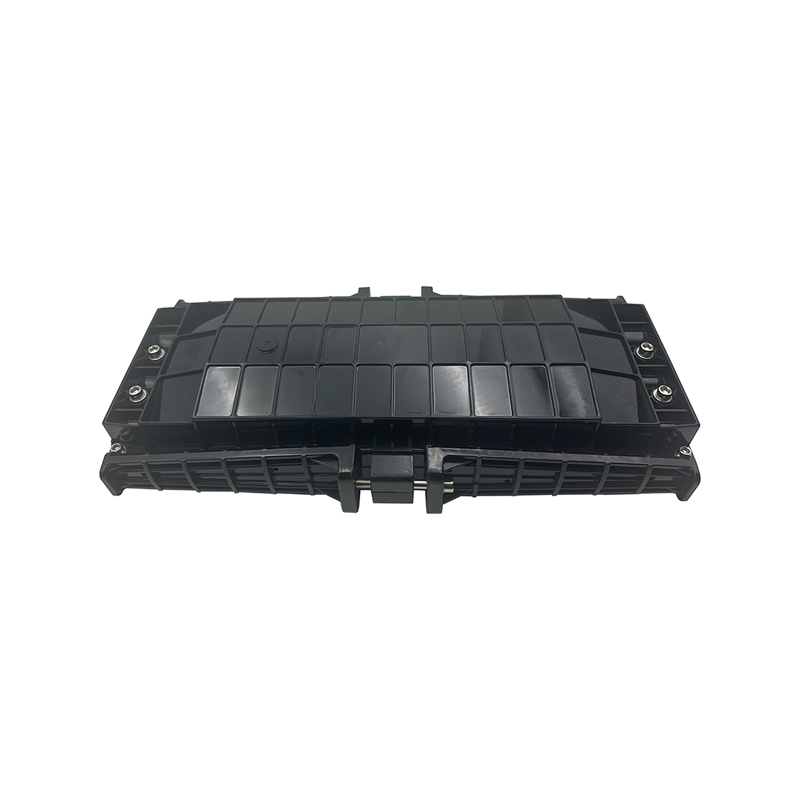
OverviewModel No. JR-2001-H10 is one of the main equipment for user access points, applied for protective connection and distribution between two or more cables. The primary function is to connect dis...
See Details -
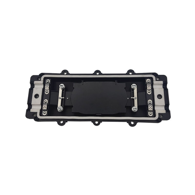
WM-2001-H09 type of It can be used to connect and branch fibers in aerial locations applications. The case body is made from high-intensity engineering plastics and shaped by mould injection under hig...
See Details -
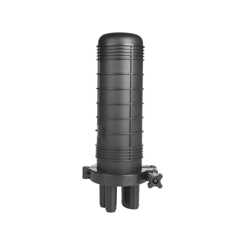
Technical data 1. Comply with various technical data of YD/T814.1-20132. Cable port:43. Cable Diameter:φ7-φ204.Max Capacity:12 Fibers 2tray=24 fibers(single)5. Sealing way: silicone rubber6. Dimension...
See Details
Ready to Get started ? Contact Us Now !

Product.
Contact Details.
-
 +86 13958188250
-
 +86 13958188250
-
 [email protected]
-
 AUDIT Email:[email protected]
- Wanma Industrial Park Taihu Yuan Town Lin'an District Hangzhou City China.
QR Code

Copyright © Wanma Technology Co., Ltd. All Rights Reserved.
Privacy
Custom Ethernet Optical Network Railway Transit Equipments Suppliers
